

Tutorials
MLX90614 Arduino Guide: GY-906 Non-Contact Temperature Sensor
Jul
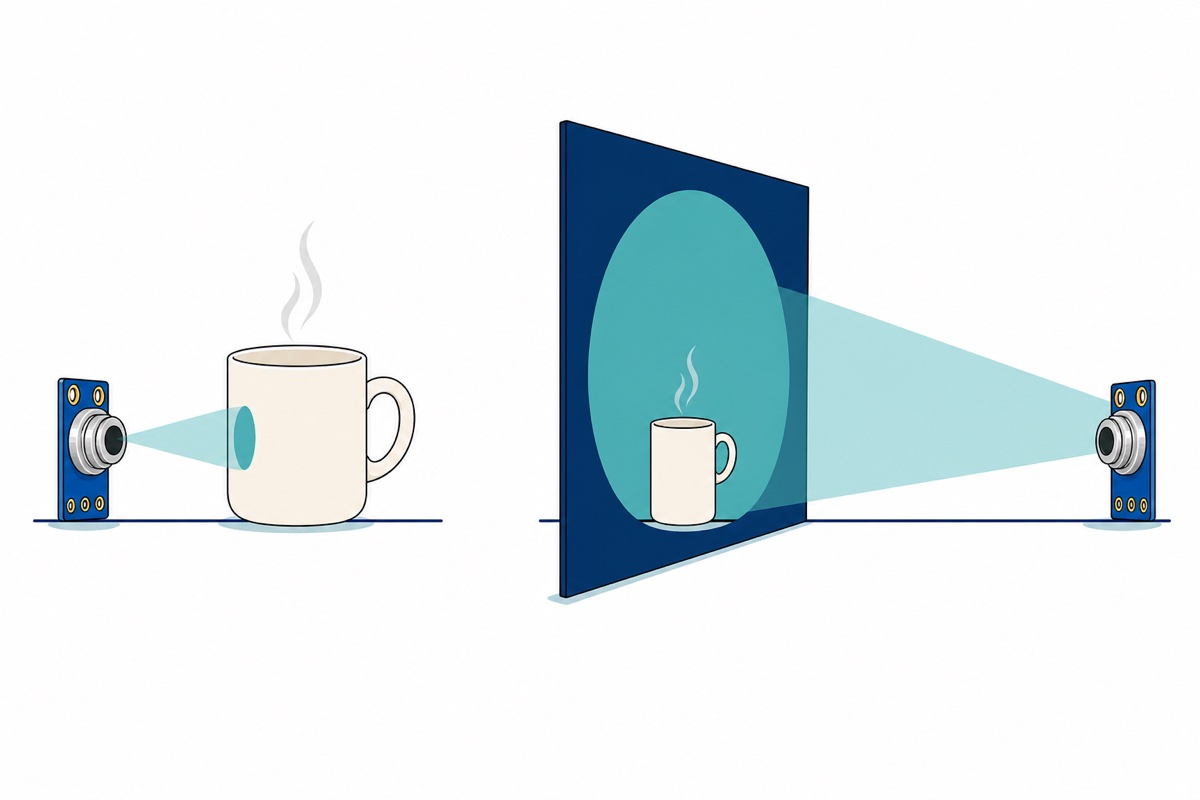
The GY-906 reads the average temperature of everything inside a 90° cone, so the patch it measures is twice as wide as its distance from the target — about 4 cm across at 2 cm away, 60 cm across at 30 cm. On an Uno it is VIN to 5V, GND to GND, SCL to A5, SDA to A4, once you have soldered on the four-pin header that travels loose in the bag. This is a hobby and industrial surface sensor, not a medical thermometer.
Read this first. Skin temperature is not core body temperature. Nothing here is a clinical measurement or medical advice; body-temperature screening needs a medically certified device, and Melexis names which MLX90614 versions qualify — this is not one of them.
What is the MLX90614 actually measuring?
The MLX90614 inside the polished silver can on the GY-906 module is a thermopile: infrared from warm objects lands on a thin membrane carrying the hot junctions of a chain of series-wired thermocouples and warms them a fraction of a degree above the cold junctions on the chip substrate, and the voltage that difference produces is the actual measurement. A difference is not yet a temperature, so the chip also measures its own package temperature and uses that as the reference the object figure is computed against. Hence the two outputs — the sensor’s own package temperature, and the object temperature — and hence the rule that matters, because everything the window can see contributes. The Melexis datasheet says it plainly: “The measured value is the average temperature of all objects in the Field Of View of the sensor”, and “the accuracy is only valid if the object fills the FOV of the sensor completely.”
Why does the reading change when you move the sensor?
The GY-906 gives you no laser dot and no viewfinder, so nothing shows how wide the averaged circle is — moving the sensor changes it, and only the arithmetic tells you by how much. Our module carries the 90° optics, so the cone’s half-angle is 45°; the circle’s radius is the distance times the tangent of the half-angle, and tan 45° = 1. The radius therefore equals the distance, and the diameter is twice the distance.
| Distance to target | Diameter of the circle being averaged | What that realistically covers |
|---|---|---|
| 2 cm | ≈ 4 cm | The face of a mug, and nothing else |
| 10 cm | ≈ 20 cm | A laptop’s whole underside |
| 30 cm | ≈ 60 cm | A head, both shoulders and the wall behind |
A hot drink proves it in half a minute. At 2 cm the 4 cm circle is entirely mug, so the number is believable. Step back to 30 cm and the same mug — call its face 8 cm across — is under 2 % of a 60 cm circle whose other 98 % is room-temperature wall, so the average lands within a degree or two of the room. Nothing drifted; you asked a different question. One caveat: Melexis defines the field of view where sensitivity has fallen to 50 %, so the circle has a soft edge and things just outside still contribute — making the practical rule stricter than the arithmetic, never looser.
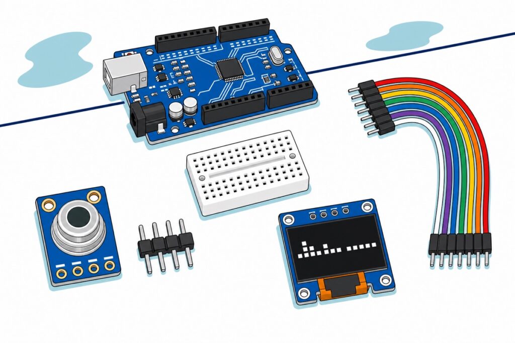
Parts list — the sensor, a display for it, and the wiring that reaches both
 GY-906 Infrared IR Temperature Sensor Module Non-Contact MLX90614 I2C Arduino
 0.96‘ OLED Display Module Blue White Screen I2C IIC Serial 128X64 LCD Display Board - 0.96' OLED WHITE
 Arduino Uno Compatible SMD UNO R3 with Type B Cable - ATMEGA328P with CH340G-Microcontroller Project
 MB102 Breadboard 170 400 830 Holes Breadboard Donut Board Arduino Prototype Multi Color - MINI BREADBOARD 170 HOLES (WHITE)
 40pcs Dupont Wire 10cm 20cm 30cm for Breadboard DIY Experiment Jumper Wire Breadboard wire - DUPONT WIRE M-M 30CM
Optional: we solder the header for you
| Item | Price | Qty | |
|---|---|---|---|
 Soldering Service for Circuit Boards & Electronics - 5 Pins Soldering ServiceSOLSE05 Soldering Service for Circuit Boards & Electronics - 5 Pins Soldering ServiceSOLSE05 | RM0.80 |
The GY-906's four-pin header ships loose and has to be soldered on. This service covers up to five pins, which is exactly this job. It is arranged by hand rather than by checkout — message us on WhatsApp first and we will sort it out with your order.
Why does the GY-906 arrive with its header not fitted?
The GY-906 ships as a bare blue board with four empty gold-plated holes along the bottom edge — VIN, GND, SCL, SDA — and its four-pin black header loose in the bag, which is what lets the same board take a straight header, a right-angle one, or wires soldered flat into an enclosure. It also means nothing connects until four solder joints exist.
Four joints at 2.54 mm pitch is a good first soldering job, and our guide to soldering header pins covers the technique. Two details are specific to this board: push the header in from the silver can side so the pins exit the back and the sensor faces away from the breadboard, and keep the iron — and later your fingers — off the polished can itself: that cap is the sensor’s optical window and its temperature reference, not a handle. Prefer not to? Our five-pin soldering service covers exactly this header. If it is your first, watching someone wet a pad and flow solder onto it beats any description:
How do two I2C devices share one Arduino Uno?
The MLX90614 and the 0.96″ OLED hang off the same two wires because I2C is an addressed bus: everything listens, only the device whose address was called answers. The sensor’s factory address is 0x5A. The OLED is an SSD1306, its address set by a jumper on the back that ships bridged on the pad marked 0x78 — the 8-bit write address, which carries the read/write bit at the bottom. Shift right by one for the 7-bit address libraries expect: 0x78 >> 1 = 0x3C. No collision, one bus. The same arithmetic covers the other option: a jumper sitting on the 0x7A pad means 0x3D, and OLED_ADDR in the sketch below has to match.
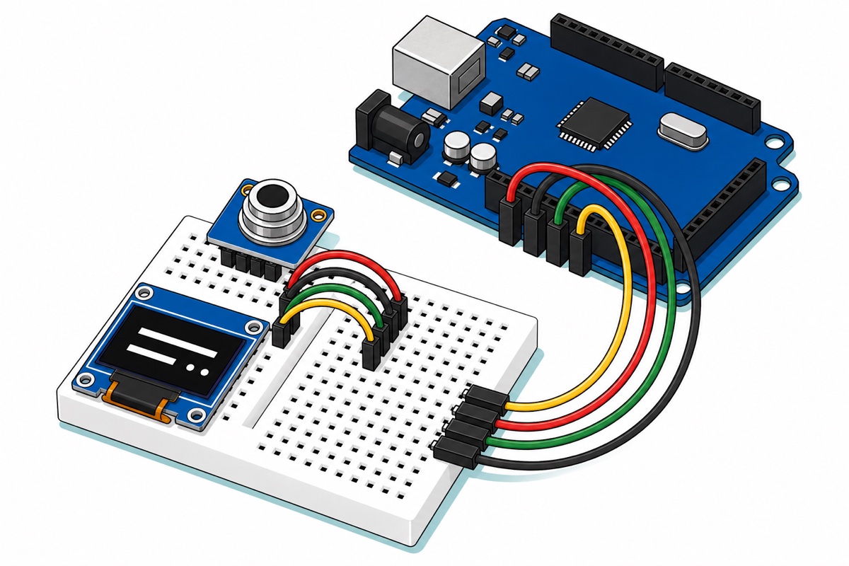
Sharing that bus is why a breadboard earns its place: each of the four nets has to reach two boards and the Uno, and one Uno pin cannot hold two jumper shells. A column of the 170-hole mini breadboard is five holes joined underneath, so each column becomes the junction where a net splits. Push the GY-906’s four pins into one bank and the OLED’s into the other, so every short jumper only has to hop the centre channel.
Both modules lie flat rather than standing up — their pins exit the back of the board, so each PCB ends up hovering a few millimetres above the breadboard with its face turned to the ceiling. Point each body out past the edge of the breadboard rather than across it, or it covers the tie points its own jumpers need; the OLED reaches about 27 mm beyond its pin row. And with the can looking upward, you aim this build by bringing the target over the sensor rather than the sensor to the target.
⚠️ The two boards do not use the same pin order. The GY-906 reads VIN, GND, SCL, SDA; the OLED reads GND, VCC, SCL, SDA. Power and ground are swapped, so copying the pattern across is the easiest way to power the display backwards. Read the OLED’s labels with the display facing you — turning it over to see the pins reverses their order.
| Net | GY-906 pin | OLED pin | Uno header |
|---|---|---|---|
| Power | VIN (1st pin) |
VCC (2nd pin) |
5V |
| Ground | GND (2nd pin) |
GND (1st pin) |
GND |
| Clock | SCL (3rd pin) |
SCL (3rd pin) |
A5 |
| Data | SDA (4th pin) |
SDA (4th pin) |
A4 |
That is eight male-to-male jumpers: four short ones joining each pair of columns, four longer ones out to the Uno‘s female headers. And 5V is the right rail even though the MLX90614 die is a 3 V-class part, because the module regulates for you — a teardown of this exact board finds a 662K regulator making 3.3 V from VIN, which accepts up to 6 V, plus 4.7 kΩ I2C pull-ups — necessarily on that regulated rail, since Melexis specifies the 3 V part’s SDA and SCL only up to its own supply. Hence it suits a 3.3 V ESP32 and a 5 V Uno equally: the ATmega328P’s datasheet puts the input-high threshold at 0.6 × VCC, or 3.0 V on a 5 V board, and 3.3 V clears that with margin.
What sketch reads it and puts the number on the OLED?
Install Adafruit MLX90614 Library, Adafruit SSD1306 and Adafruit GFX from the Library Manager. All three depend on Adafruit BusIO, and a missing BusIO is the usual reason this refuses to compile. One naming trap: the method is writeEmissivity(), not the setEmissivity() several third-party guides name — the shipped header settles it.
// GY-906 (MLX90614) infrared sensor + 0.96" OLED on an Arduino Uno.
// One I2C bus: SDA -> A4, SCL -> A5. Sensor answers at 0x5A, display at 0x3C.
// This is a DEMONSTRATION of an infrared surface measurement.
// It is not a medical thermometer and no reading here is a health measurement.

#include <Wire.h>
#include <Adafruit_MLX90614.h>
#include <Adafruit_GFX.h>
#include <Adafruit_SSD1306.h>

#define OLED_ADDR 0x3C   // the 0x78 write address shifted right by one bit

Adafruit_SSD1306 display(128, 64, &Wire, -1);
Adafruit_MLX90614 mlx;

void setup() {
  Serial.begin(9600);
  Wire.begin();
  delay(300);   // datasheet: readings are only valid 250 ms after power-up

  // Adafruit_SSD1306::begin() returns false only if its frame buffer will not
  // fit in SRAM - it never checks that the display replied, so ask the bus.
  Wire.beginTransmission(OLED_ADDR);
  if (Wire.endTransmission() != 0) {
    Serial.println(F("No OLED at 0x3C. Check SDA/SCL and the address jumper."));
    while (1) { }
  }
  display.begin(SSD1306_SWITCHCAPVCC, OLED_ADDR);
  display.clearDisplay();
  display.setTextColor(SSD1306_WHITE);

  if (!mlx.begin()) {          // begin() is false when 0x5A does not answer
    display.setTextSize(1);
    display.setCursor(0, 8);
    display.println(F("No MLX90614 at 0x5A"));
    display.println(F("Check the four"));
    display.println(F("solder joints."));
    display.display();
    Serial.println(F("Nothing answered at 0x5A."));
    while (1) { }
  }

  // Emissivity is stored in the sensor's own EEPROM and survives power cycles.
  Serial.print(F("Stored emissivity: "));
  Serial.println(mlx.readEmissivity(), 2);   // 1.00 as it leaves the factory
}

void loop() {
  double object  = mlx.readObjectTempC();    // average over the whole cone
  double ambient = mlx.readAmbientTempC();   // the sensor package itself

  display.clearDisplay();

  if (isnan(object) || isnan(ambient)) {     // a failed read returns NAN
    display.setTextSize(1);
    display.setCursor(0, 28);
    display.println(F("Read failed"));
  } else {
    display.setTextSize(1);
    display.setCursor(0, 0);
    display.print(F("SURFACE avg in FOV"));

    display.setTextSize(3);
    display.setCursor(0, 18);
    display.print(object, 1);
    display.print(F("C"));

    display.setTextSize(1);
    display.setCursor(0, 52);
    display.print(F("sensor body "));
    display.print(ambient, 1);
    display.print(F("C"));

    Serial.print(object, 2);
    Serial.print(F(" C surface / "));
    Serial.print(ambient, 2);
    Serial.println(F(" C sensor body"));
  }

  display.display();
  delay(500);
}
Three deliberate choices there. Adafruit_MLX90614::begin() returns a bool that is false when nothing acknowledges 0x5A, so the sketch halts and names the chip instead of printing zeros forever. The display needs a probe of its own, because in the Adafruit_SSD1306 source begin() returns false only when the frame buffer will not fit in SRAM — it never asks whether the OLED replied — so the sketch pings 0x3C over Wire itself. A failed read returns NAN, so the values go through isnan() rather than a comparison. And the 300 ms wait exists because the datasheet only guarantees valid results 250 ms after power-up. Keep every string in F(): Adafruit_SSD1306 claims a 1024-byte frame buffer, half the Uno’s SRAM, on top of this sketch’s 538 static bytes.
Upload it and redo the mug test, this time on the OLED: up close the big figure is the mug, and as you lift the mug away it walks down toward the sensor-body figure below it. Do not leave a hot object parked over the can, though — it warms the package itself, the one condition the accuracy figures assume you have avoided.
Why does a shiny metal surface read far too cold?
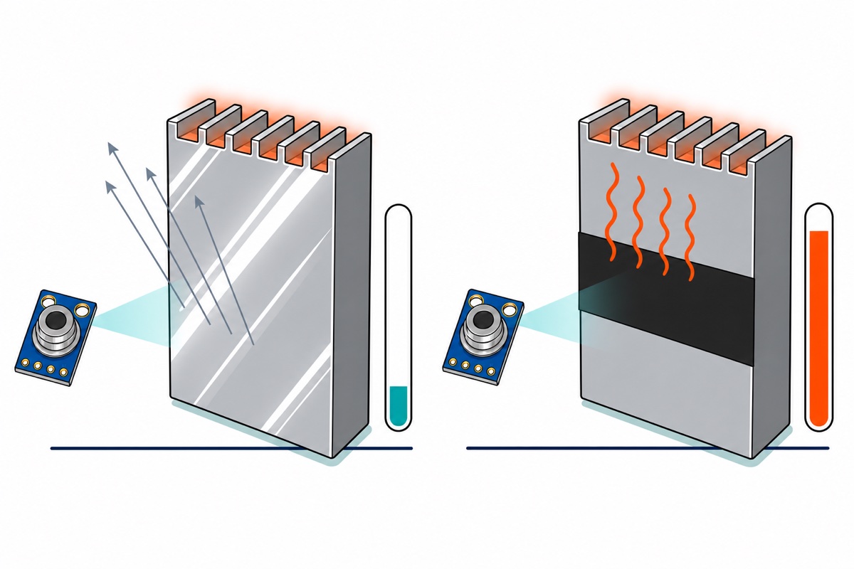
Because the MLX90614 leaves the factory calibrated for a perfect radiator — “As a standard, the MLX90614 is calibrated for an object emissivity of 1”. Emissivity is the fraction of infrared a surface emits compared with a theoretically perfect emitter at the same temperature, and Melexis puts roughly polished aluminium at 0.18, heavily oxidised aluminium at only 0.30, and ordinary paint at 0.85–0.95.
What reaches the sensor is the infrared the surface emits itself — proportional to its emissivity times the fourth power of its absolute temperature — plus the room’s infrared that it reflects. A poor emitter is by the same token a good mirror, so most of what comes back is a picture of the room. Put numbers on it: a 60 °C polished aluminium heatsink in a 30 °C room emits 18 % of what a black body at 60 °C would and reflects 82 % of a 30 °C room — a total radiance equivalent to roughly 36 °C. That is the whole explanation for “my heatsink reads barely above room temperature”.
The fix is matt tape or matt paint on the spot you want to read, not a different sensor: redo the sum at 0.95 and that same heatsink reads about 58.7 °C. You can also tell the sensor the true emissivity in one line, but knowingly — mlx.writeEmissivity(0.95) writes internal EEPROM, so it survives power cycles and biases every later reading until you overwrite it — including next month’s readings on something else. Printing mlx.readEmissivity() at start-up, as the sketch does, keeps that visible, and mlx.writeEmissivity(1.0) puts the factory value back.
Can you use this to check someone’s temperature?
No — the GY-906 carries the wrong MLX90614 for that, and Melexis settles it in the datasheet rather than leaving it to interpretation. Medical accuracy on this family — ±0.2 °C over a narrow window around body temperature — “is only available for the MLX90614Dxx versions”, and the parts complying with ASTM E1965-98, the standard for infrared thermometers used on patients, are named individually: the ESF-DCC, ESF-DCH and ESF-DCI. Their fields of view are 35°, 10° and 5° — all narrow, precisely because a wide cone cannot isolate a forehead from the hair, the wall and the air conditioning behind it.
Our module’s 90° optics puts it in a different category by design, and the same document confirms it a second way: the Dxx parts run a higher amplifier gain that caps their object temperature near 200 °C, while this part is specified to 380 °C. That ceiling is what makes it good at what it is for — soldering irons, motors, brake discs, cooking surfaces, 3D printer hot ends. For a person, use a certified clinical thermometer.
Common mistakes we see
Standing back and expecting a point reading. The commonest disappointment by far. At arm’s length the sensor averages a circle wider than a person, so the number sags toward room temperature.
Pointing it at bare metal. Shiny surfaces read dramatically low at the default emissivity of 1.0. Matt tape on the spot, or write the true emissivity and remember that it stays written.
Holding the can, or mounting it beside something warm. The object figure is computed against the sensor’s own package temperature, so fingers on the metal can or a hot regulator next door corrupt the reference itself — which is why the datasheet’s accuracy holds only while no temperature difference exists across the package.
Reading the instant you plug it in, especially outdoors. Carrying the board from air conditioning into 33 °C leaves it far from equilibrium for minutes; let it settle. Same for a sagging USB rail — supply dependence is about 0.6 °C per volt.
FAQ
How far away can the MLX90614 measure?
As far as you like — but the further away, the larger the area averaged. With this module’s 90° field of view the circle is twice as wide as the distance: 2 cm gives 4 cm, 30 cm gives 60 cm. Accuracy holds only while the object fills it.
Can I use the GY-906 as a fever or body-temperature thermometer?
No. It is a hobby and industrial surface sensor, skin temperature is not core temperature, and Melexis restricts medical accuracy to the narrow-field MLX90614Dxx parts complying with ASTM E1965-98. Use a certified device for people.
Why does my GY-906 read much colder than the object really is?
Almost always emissivity. The sensor ships calibrated for a perfect radiator, so polished metal — around 0.18 for aluminium — mostly reflects the room back at it. Stick matt tape on the spot, or write the true emissivity to the sensor.
Does the GY-906 need a 3.3V board, or is 5V safe?
5V is fine. The module carries its own 3.3 V regulator on VIN, which accepts up to 6 V, and its I2C pull-ups go to that rail. An Uno reads a HIGH from 3.0 V upward, so 3.3 V is well in range — and the same module works on a 3.3 V ESP32.
Can the sensor and the OLED share the same two pins?
Yes. I2C is addressed: the MLX90614 answers at 0x5A and this SSD1306 at 0x3C, so both sit on A4 and A5. Our DHT11 and OLED guide and MPU6050 tilt guide use the same pattern.
Last updated August 2026. Stuck? Chat with us on WhatsApp.
