

Tutorials
Arduino Traffic Light Project: 3 LEDs, One Afternoon
Jun
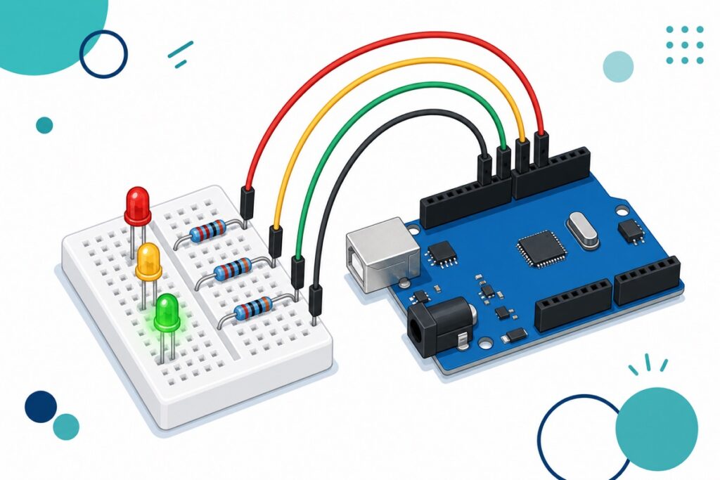
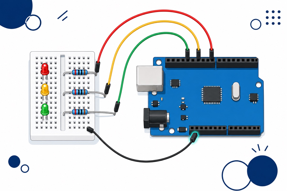
An Arduino traffic light project is three LEDs (red, yellow, green) wired to three digital pins on an Arduino Uno, each through a 220Ω series resistor, with all the short legs sharing one ground row on the breadboard. The code lights one LED at a time in a red → green → yellow cycle. Done in an afternoon.
How does an Arduino traffic light project work?
An Arduino traffic light is really three separate LED circuits that one program switches on in turn. The Arduino Uno doesn’t “know” what a traffic light is — it just sends 5V to one pin, waits a few seconds, switches it off, then turns on the next pin.
The Malaysian cycle is simple: red to stop, green to go, yellow as a warning before red returns — no combined red+yellow phase like in the UK. That is why it stays a classic school RBT project: the concept fits in one sentence, yet it teaches digital outputs, component polarity, Ohm’s law and program structure at once.
What components do you need?
The parts list for this Arduino traffic light project is short and cheap. Everything plugs into a breadboard with no soldering, so it is safe even for a Form 1 student.
Parts list
 Arduino Uno Compatible SMD UNO R3 with Type B Cable - ATMEGA328P with CH340G-Microcontroller Project
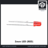 Round Head LED 3mm / 5mm / 8mm - Red/Yellow/Blue/Green/White - 3mm RED
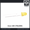 Round Head LED 3mm / 5mm / 8mm - Red/Yellow/Blue/Green/White - 3mm YELLOW
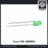 Round Head LED 3mm / 5mm / 8mm - Red/Yellow/Blue/Green/White - 3mm GREEN
 400 pcs 1/4W Resistor Pack Resistor Kit 20 Common Value with 20 each
 MB102 Breadboard 170 400 830 Holes Breadboard Donut Board Arduino Prototype Multi Color - MINI BREADBOARD 170 HOLES (WHITE)
 40pcs Dupont Wire 10cm 20cm 30cm for Breadboard DIY Experiment Jumper Wire Breadboard wire - DUPONT WIRE M-M 30CM
There is also a ready-made traffic light module — a small black PCB with three 5mm LEDs stacked vertically and a 4-pin header (G, Y, R, GND). It is neater and can be ordered straight from its product page. For an RBT folio we still recommend the separate-LED build above — that is the wiring teachers want to see you understand piece by piece.
Why does every LED need a series resistor?
A digital pin on the Arduino Uno puts out the full 5V when HIGH, but an LED is not an ordinary bulb — it is a diode. Once the voltage crosses the LED’s forward voltage (Vf), its internal resistance drops to nearly zero and current climbs unchecked, burning out the LED and the Arduino pin with it.
The official numbers: Arduino lists DC Current per I/O Pin = 20 mA for the Uno Rev3, and that is the safe limit to design for. The ATmega328P datasheet states 40.0 mA per I/O pin and 200.0 mA across all VCC and GND pins — but an “absolute maximum rating” marks the point of damage, not a target. The maths is straight Ohm’s law:
I = (5V − Vf) / RVf varies by colour. A 3mm red LED is typically 1.8–2.2V, while yellow and green sit higher at 2.0–2.4V.
| 3mm LED colour | Typical Vf | Current with 220Ω | Current with 330Ω |
|---|---|---|---|
| Red | 1.8–2.2V | ≈12.7–14.5 mA | ≈8.5–9.7 mA |
| Yellow | 2.0–2.4V | ≈11.8–13.6 mA | ≈7.9–9.1 mA |
| Green | 2.0–2.4V | ≈11.8–13.6 mA | ≈7.9–9.1 mA |
Our pick: 220Ω. It puts all three LEDs at around 12–14.5 mA — bright enough for a classroom demo, and still under the 20 mA limit with a comfortable margin. Even if all three lit at once, the total is only about 42 mA.
The blue metal-film resistors use 5 bands: 220Ω = red-red-black-black-brown, 330Ω = orange-orange-black-black-brown. If the bands make your head spin, measure with a digital multimeter instead. Anything from 180Ω to 470Ω works for all three colours; bigger values are just dimmer. Keep 150Ω for green only — on a red LED it can reach ≈21 mA, slightly past the 20 mA limit.
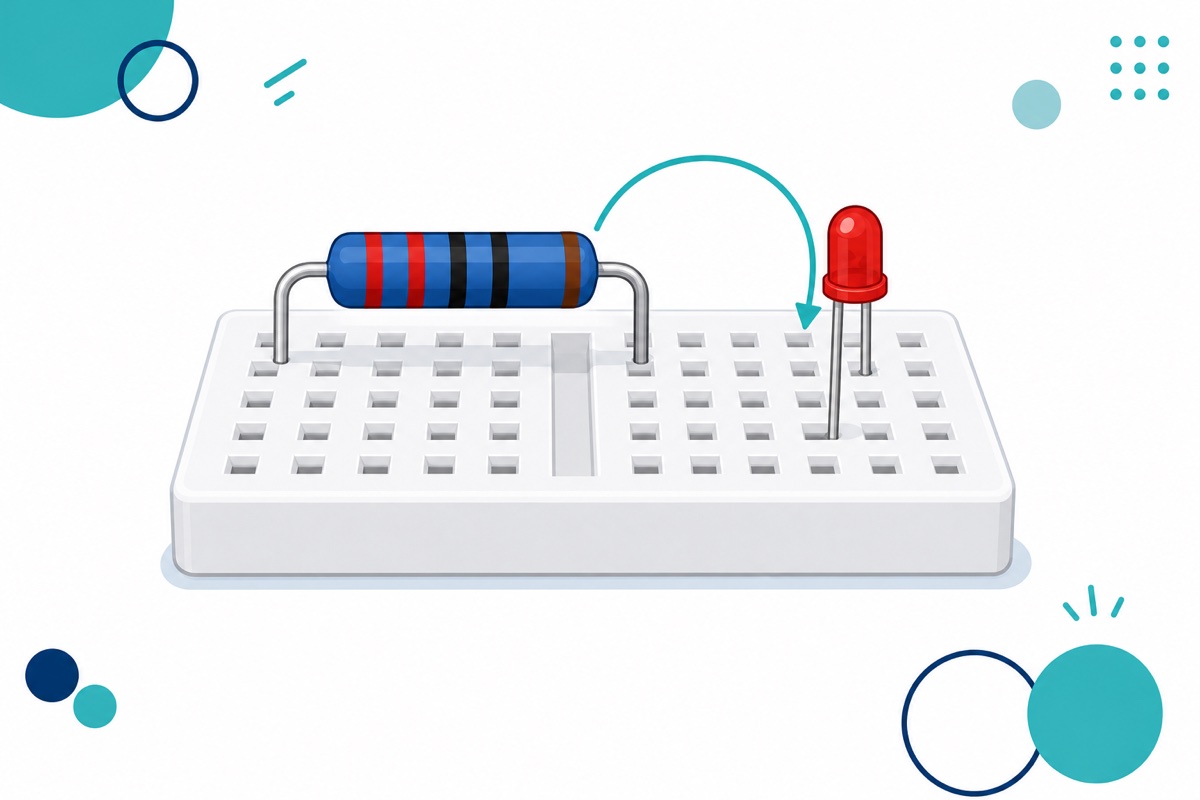
How do you tell an LED’s long leg from its short leg?
A 3mm LED has two legs of different lengths, and that is not a factory defect — it is the polarity marker. Check this before pushing the LED into the breadboard, because a reversed LED simply stays dark and gives no clue why.
| Physical feature | Terminal | Connect to |
|---|---|---|
| Long leg | Anode (+) | Resistor → Arduino digital pin |
| Short leg, flat spot on the edge of the dome | Cathode (−) | Shared ground row on the breadboard |
If the legs have been trimmed equal, find the flat spot on the rim of the plastic dome — the flat side is always the cathode. A third clue: inside the clear dome, the larger metal piece is usually the cathode, but there are exceptions, so trust the short leg and flat spot first.
How do you wire it all up on the breadboard?
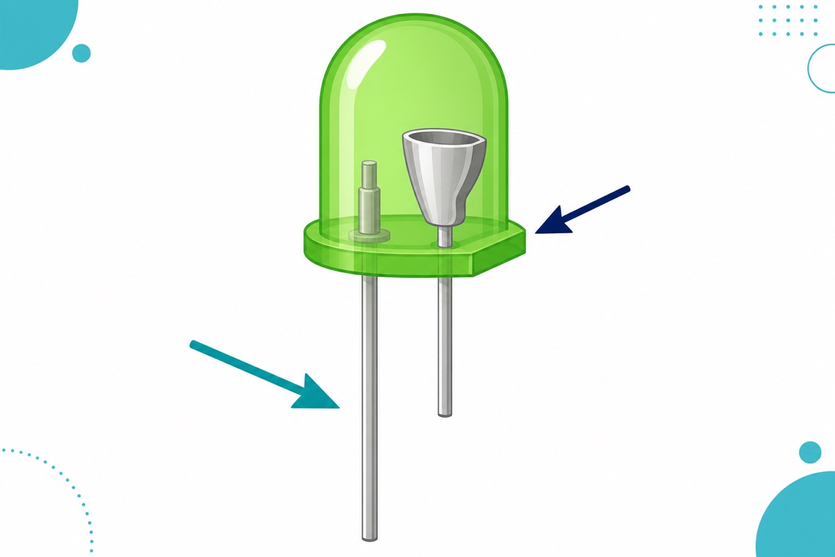
The 170-hole mini breadboard has enough room for this Arduino traffic light project if you lay it out neatly. One important thing: this mini breadboard has no +/− power rails along the sides like bigger breadboards — so pick one ordinary 5-hole row (the end row, for example) and make it the shared ground row. All the short legs must gather in that row, and that same row connects to the Arduino’s GND pin with a single jumper wire.
| Component | Leg / end | Connect to |
|---|---|---|
| Red LED | Long leg (anode) | 220Ω resistor → pin 10 |
| Short leg (cathode) | Shared ground row on the breadboard | |
| Yellow LED | Long leg (anode) | 220Ω resistor → pin 9 |
| Short leg (cathode) | Shared ground row on the breadboard | |
| Green LED | Long leg (anode) | 220Ω resistor → pin 8 |
| Short leg (cathode) | Shared ground row on the breadboard | |
| GND jumper | One wire | Shared ground row → Arduino GND pin |
Notice that the 5V pin is never used. The digital pin itself supplies the 5V whenever the code sets it HIGH — that is the whole idea of this project. We also deliberately avoid pin 13, which is shared with the Arduino’s onboard LED and will blink along and confuse you while debugging.
One note on breadboards: holes connect in rows, split by the trench down the middle. Place each resistor across that trench — if both ends land in the same row, it shorts itself out.
Want to see real hands pressing LEDs and resistors into a breadboard? This video shows the same build from scratch:
What is the complete Arduino code for the traffic light cycle?
The Arduino code below is complete and uploads straight to the Uno with no extra libraries. Every phase duration lives in a named constant at the top — change one number there and the whole cycle changes, without touching loop().
// Arduino traffic light project - 3 LEDs on an Arduino Uno
// Malaysian cycle: RED -> GREEN -> YELLOW -> RED (repeats)

const int PIN_RED    = 10;   // red LED anode    through a 220 ohm resistor
const int PIN_YELLOW = 9;    // yellow LED anode through a 220 ohm resistor
const int PIN_GREEN  = 8;    // green LED anode  through a 220 ohm resistor

// Duration of each phase in milliseconds - tune the values here
const unsigned long TIME_RED    = 5000;   // 5 seconds: traffic stops
const unsigned long TIME_GREEN  = 4000;   // 4 seconds: traffic goes
const unsigned long TIME_YELLOW = 2000;   // 2 seconds: warning before red

void allOff() {
  digitalWrite(PIN_RED,    LOW);
  digitalWrite(PIN_YELLOW, LOW);
  digitalWrite(PIN_GREEN,  LOW);
}

void setup() {
  pinMode(PIN_RED,    OUTPUT);
  pinMode(PIN_YELLOW, OUTPUT);
  pinMode(PIN_GREEN,  OUTPUT);
  allOff();                   // start with every light off
}

void loop() {
  // PHASE 1 - RED
  allOff();
  digitalWrite(PIN_RED, HIGH);
  delay(TIME_RED);

  // PHASE 2 - GREEN
  allOff();
  digitalWrite(PIN_GREEN, HIGH);
  delay(TIME_GREEN);

  // PHASE 3 - YELLOW
  allOff();
  digitalWrite(PIN_YELLOW, HIGH);
  delay(TIME_YELLOW);

  // loop() repeats on its own - back to PHASE 1
}
The allOff() function is called before every phase so that only one light is on at a time. Remove that call, and the previous LED stays lit until all three are glowing at once.
About delay(): for this project it is the right choice — simple, readable, and a traffic light is supposed to wait. But delay() blocks: the Arduino genuinely stops and cannot read a button or sensor for the whole duration — once you add a pedestrian button, that is the moment to learn the millis() pattern.
How do you turn this into a school project that scores marks?
The basic Arduino traffic light works, but teachers have seen the three-LED version dozens of times. The marks come from one addition you can explain yourself in front of the class — pick just one and do it properly.
- Pedestrian button. A push button that forces the cycle into the red phase early — the most natural excuse to learn
millis(), becausedelay()will “miss” the press. - A second junction. Three more LEDs for a cross street, coded so that green in one direction means red in the other. The Uno has 14 digital pins — enough and to spare.
- Buzzer for accessibility. A beep during the safe-to-cross phase, like the audio warning at real junctions. The accessibility touch catches an examiner’s eye.
- A 3D-printed traffic light housing. A printed pole and lamp hood turns the bare breadboard into a model of a real junction.
For a second school project on the same foundation, a line follower robot adds sensors and motors on top of the same Uno.
Common mistakes we see from real customers
LED plugged in backwards
This is number one, and it is confusing because nothing gets damaged — the LED just stays silent. A diode passes current in one direction only. If a single LED refuses to light while the other two work, pull it out and rotate it 180° before blaming the code.
Skipping the resistor
Some people try it without resistors, “just for a moment”. The LED may glow very bright for a few seconds, then go permanently dim or die outright — and the Arduino pin may go with it. Fit all three resistors before plugging in the USB cable, not after.
Cathodes not sharing the same ground
If one short leg lands in a row that is not connected to the shared ground row, only that LED goes dark while the others behave normally — a pattern that is easy to misread as a faulty LED.
Using the 5V pin instead of a digital pin
Connecting an anode to the 5V pin does light the LED, but it stays on forever and your code has no effect. The 5V pin is always live; only digital pins like 0–13 (and A0–A5, which double as digital pins) can be controlled by digitalWrite().
Copied code with the wrong pin numbers
Code from the internet often uses pins 13, 12, 11 while your wiring is 10, 9, 8 — every LED looks “dead” even though the circuit is perfect. Check that the three const int lines match the actual wires before blaming the board.
FAQ
Can I use 5mm LEDs instead of 3mm LEDs?
Yes, it is a straight swap. Vf and operating current are nearly identical for the same colour, so the 220Ω resistor stays right. A 5mm LED is just bigger, with thicker legs.
Why does the green LED look dimmer than the red one?
Because green’s Vf is higher (2.0–2.4V versus 1.8–2.2V for red), so with the same resistor it receives slightly less current. That is normal. For balanced brightness, use 150Ω for green only.
Do I need an external power supply for this project?
No. The USB cable from a laptop is plenty for three LEDs drawing around 13 mA each. The black barrel jack on the Arduino Uno is for heavier projects like motors, or for when the board must run on its own without a laptop during a presentation.
How many seconds should each light stay on?
There is no single answer — real junctions vary with traffic. For a classroom demo, 5 seconds red, 4 seconds green and 2 seconds yellow gives a cycle quick enough to watch. The yellow phase should stay the shortest because it is a warning, not a waiting state.
Is the ready-made traffic light module a better choice?
The module is neater, but it hides exactly the parts your teacher checks: LED polarity, the resistor calculation and the shared ground row. For an RBT folio, the separate-LED build is easier to defend during Q&A.
Want a permanent build instead of a breadboard one? The LEDs and resistors can be soldered straight onto perfboard — the basic technique is the same as in our how to solder header pins guide.
Last updated August 2026. Stuck? Chat with us on WhatsApp.

Pingback: What Is Arduino? A Complete Beginner's Guide From Zero