

Tutorials
XL4005 vs XL4015 vs LM2596: Which Buck Converter to Buy
Nov
Quick answer: The XL4005 and XL4015 are both 5A-class adjustable step-down (buck) boards. Pick by your input voltage. The XL4005 runs from 5V to 32V, so take it for anything under 8V in (a 2-cell 18650 pack). The XL4015 needs 8V to 36V and has more margin on a 24V system. Plan on about 3A continuous from either bare board and about 2A from an LM2596. Above 3A, move up to the XL4016 with its heatsinks.
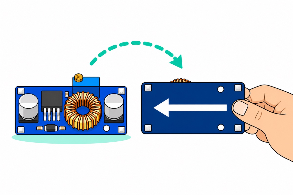
- Flip the board over. The underside print says 4005 or 4015.
- Solder wires to the four corner pads. Feed it at least 1.5 to 2V more than the output you want, and never under 5V (XL4005) or 8V (XL4015). Check plus and minus first: a reversed supply can destroy the board.
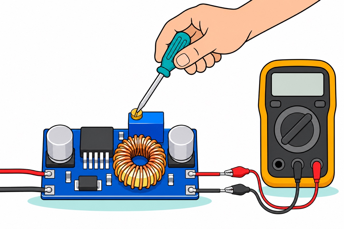
- With nothing on the output, put a multimeter (DC volts) on OUT+ and OUT−.
- Turn the brass trimmer screw to your voltage. Then switch off and connect the load.
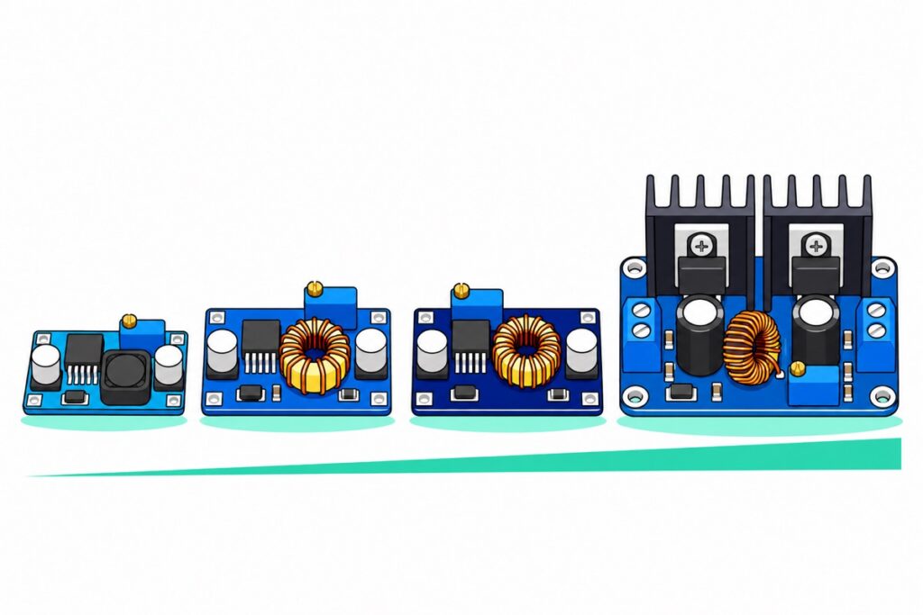
XL4005, XL4015, LM2596 and XL4016 side by side
The XL4005, XL4015, LM2596 and XL4016 boards all step a higher DC voltage down to one you set with a trimmer screw (to raise a voltage, see boost vs buck). Chip figures are from the XLSEMI datasheets (XL4005, XL4015, XL4016) and TI’s LM2596 datasheet.
| LM2596 (no display) | XL4005 | XL4015 | XL4016 | |
|---|---|---|---|---|
| Input voltage | 4.5V to 40V | 5V to 32V | 8V to 36V | 8V to 36V |
| Absolute maximum input | 45V | 35V | 40V | 40V |
| Lowest output | 1.23V | 0.8V | 1.25V | 1.25V |
| Headline current | 3A | 5A | 5A | 8A (module rating) |
| Plan on (continuous, no fan) | About 2A (LM2596 guide) | About 3A | About 3A | About 4 to 5A, or 8A with a fan (XL4016 guide) |
| Switching frequency | 150kHz | 300kHz | 180kHz | 180kHz |
| Cooling | None, bare board | None, bare board | None, bare board | Two finned heatsinks |
| Connections | Four solder pads | Four solder pads | Four solder pads | Screw terminals |
| How to spot it | Black sealed block inductor, no copper wire showing | Open copper coil. Underside print 4005 | Open copper coil. Underside print 4015 | Two tall black heatsinks |
| Best for | Sensors, microcontrollers and other loads under 2A | Sources under 8V, 2-cell 18650 packs, outputs below 1.25V | 12V and 24V systems up to 3A | Loads above 3A, or no soldering |
Parts you need
The XL4005, XL4015 and no-display LM2596 boards have four bare corner pads, so you solder on four wires (how to solder). Under 2A, the LM2596 version with a display and screw terminals needs no soldering, and its display does the meter’s job.
The four step-down boards (pick one)
 XL4005 XL4015 Step Down DC-DC Buck Converter Module 5A Adjustable LM2596S Replacement - XL4005 5A BUCK CONVERTOR (5-32V)
 XL4005 XL4015 Step Down DC-DC Buck Converter Module 5A Adjustable LM2596S Replacement - XL4015 5A BUCK CONVERTOR (4-38V)
 LM2596S DC-DC Buck Converter Step Down Power Module 4-40V to 1.25-37V Voltage Regulator Board - LM2596S BUCK CONVERTOR
 XL4016 DC-DC Buck Converter Step Down Power Supply Module 8A 300W High Power Voltage Regulator
For setting the voltage
| Item | Price | Qty | |
|---|---|---|---|
 XL830L Digital Multimeter with backlight Portable Multimeter Electronics ProjectMULTIME | RM25.95 | ||
 Crocodile Clip Cables 46cm Alligator Clip Cable Multi ColorCROWIRE | RM4.15 |
The meter is how you set the output. The clip leads hold its probes on the output wires while you turn the trimmer. They are for the meter only, not for carrying the load.
XL4005 vs XL4015: what is the real difference?
The XL4005 and XL4015 are both rated 5A by XLSEMI, in the same five-leg package. What separates them is the voltage each chip accepts.
Input. XLSEMI guarantees the XL4005 from 5V to 32V and the XL4015 from 8V to 36V. Below its minimum the datasheet promises nothing: the output may sag or cut out.
Lowest output. Each chip compares a fraction of its output with a fixed internal reference, and the trimmer sets that fraction. At one end of the trimmer the whole output is compared, so the output equals the reference: 0.8V on the XL4005, 1.25V on the XL4015.
| Your source | You want | Pick | Why |
|---|---|---|---|
| 2-cell 18650 pack, 6.0 to 8.4V (a 2-slot holder, common on school and FYP robots) | 5V | XL4005 | The pack is under the XL4015’s 8V minimum for most of its discharge. Near empty (about 6V) it is only 1V above 5V, so a heavy load can pull the 5V down. Recharge at that point |
| 3-cell 18650 pack, 9.0 to 12.6V | 5V | XL4005 or XL4015 | Always above 8V |
| 12V adapter or 12V battery | 5V or 3.3V, up to 3A | XL4005 or XL4015 | Well inside both ranges |
| 24V supply | 12V or 5V, up to 3A | XL4015 | 24V is 12V under its 36V limit, and its input capacitor is a 50V part. The XL4005 has 8V to spare and a 35V capacitor. Motors and long cables put short spikes on a supply rail, so the extra room matters |
| 8V to 36V | More than 3A continuous | XL4016 | Heatsinks on the chip and on the diode |
Size the supply by watts. A buck converter trades volts for amps. 5V at 3A is 15W, or about 17W in at 88% efficiency, and 17W from 12V is only 1.4A. A 12V 2A supply is enough (choosing a DC supply).
How to tell the XL4005 board from the XL4015 board
The XL4005 and XL4015 boards are the same size with the same open copper coil, so read the print. The underside number and the chip marking are the reliable checks. Other parts can change between production batches.
| Check | XL4005 board | XL4015 board |
|---|---|---|
| Option name in the listing’s dropdown | XL4005 5A BUCK CONVERTOR (5-32V) | XL4015 5A BUCK CONVERTOR (4-38V) |
| Input range to plan your supply by (chip datasheet) | 5V to 32V | 8V to 36V |
| Print on the underside (reliable) | 4005 DC-DC | 4015 |
| Marking on the black chip (reliable) | XL4005E1 | XL4015E1 |
| Code on the blue trimmer | W103 (10k) | W503 (50k) |
| Print on the input capacitor (µF, volts), beside IN+ | 220 35V | 100 50V |
| Print on the output capacitor (µF, volts), beside OUT+ | 220 35V. Keep the output setting under 30V | 220 35V. Keep the output setting under 30V |
| Board colour | Medium blue | Darker blue |
How much current can each board really give?
The XL4005, XL4015 and LM2596 boards have no heatsink, so heat sets their real limit. The 5A in XLSEMI’s datasheets is what the chip itself can deliver. Heat decides how much of that a bare board can keep up. Efficiency is the share of input power that reaches the load. The rest stays on the board as heat: heat = power out ÷ efficiency − power out. With datasheet efficiencies:
| Board and load | Efficiency | Heat on the board | Chip temperature rise (30°C per watt) | Chip temperature in a 33°C room |
|---|---|---|---|---|
| XL4015, 12V in, 5V out, 5A (25W) | 87% | 25 ÷ 0.87 − 25 = 3.7W | 111°C | 144°C, over the limit |
| XL4005, 12V in, 5V out, 5A (25W) | 90% | 25 ÷ 0.90 − 25 = 2.8W | 84°C | 117°C, no margin |
| XL4015, 12V in, 5V out, 3A (15W) | About 88% (efficiency curve) | About 2W | About 60°C | About 93°C |
| XL4015, 24V in, 12V out, 3A (36W) | 93% | 36 ÷ 0.93 − 36 = 2.7W | 81°C | 114°C, little margin |
| LM2596, 12V in, 5V out, 3A (15W, same chip package) | 80% | 15 ÷ 0.80 − 15 = 3.75W | About 113°C | About 146°C, over the limit |
The last two columns use XLSEMI’s figure for the chip’s package, 30°C of rise per watt with no heatsink, against its 125°C limit. 33°C is a warm Malaysian room without air-con. TI rates the LM2596 at 30°C per watt only with 2.5 square inches of copper under it, and at 50°C per watt with 0.5 square inch, so on a small board its rise is higher still. This rough sum puts all the heat in the chip. The diode and coil take a share, but they sit on the same small board.
At 5A the XL4015 is over the limit and the XL4005 has nothing to spare. At 3A and 5V out there is room for a warm day or a closed box, so plan on about 3A. At 12V out the same amps carry more watts and leave more heat, so give the board open air.
The LM2596 makes the same heat at only 3A because of its switch. While a switch is on, its voltage drop times the current becomes heat. The LM2596’s bipolar transistor drops about 1.16V at 3A, so 3.5W while it is on. The XL4015’s 60 milliohm MOSFET drops 0.3V at 5A (5 × 0.06), so 1.5W while it is on. Less heat per amp means more amps.
An overheated chip shuts its output off until it cools, so a board that cuts out and restarts under load is too hot. At 3A the chip and coil can burn a finger. Mount the board on standoffs through its two holes, never flat on metal: the underside has bare solder joints.
Step by step: set the output voltage with a multimeter
The XL4005 and XL4015 arrive with the trimmer at any setting, so a new board fed 12V can put almost 12V into a 5V circuit. Set the voltage before you connect the load.
- Solder four wires to IN+, IN−, OUT+ and OUT−, sized for your current. Dupont jumpers are signal wire, good for about 1A (wire table in the XL4016 guide).
- Connect the input only and check plus and minus twice: these boards have no reverse-polarity protection. The input must be 1.5 to 2V above your output, because the switch, coil and wires each drop a little, and more as current rises. It must also be at least 5V (XL4005), 8V (XL4015) or 4.5V (LM2596).
- Put the meter on the output. Set the XL830L multimeter to 20V DC (200V DC if your input is above 20V), red probe on the OUT+ wire, black on OUT−. Crocodile clip leads hold the probes so both hands are free (meter basics).
- Switch on and turn the trimmer’s brass screw slowly. It is a multi-turn part, so several turns with no change are normal. Direction can differ between batches: trust the meter, and reverse if many turns change nothing. If the reading stops just under your input voltage, the input is too low for that setting.
- Switch off, connect the load, switch on and measure again at the load.
When to move up to the XL4016
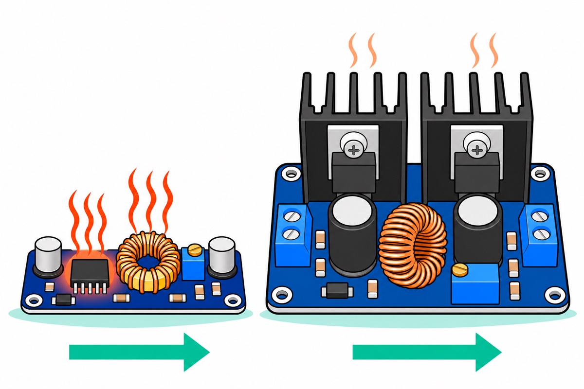
The XL4016 board is the one to buy when your load stays above 3A. Past 3A, the heat on a bare XL4005 or XL4015 climbs towards the 2.8 to 3.7W in the sum above, with only the board’s copper to lose it. A heatsink stuck on the chip helps only a little: the chip sheds most of its heat through its metal tab, which is soldered to the board.
The XL4016 bolts one finned heatsink to its chip and another to its diode, so the heat is split between two parts with fins to hand it to the air. Its screw terminals need no soldering (XL4016 setup guide).
FAQ
Can the XL4015 run from 5V or a 7.4V battery?
No. The XL4015 needs at least 8V, and a 7.4V pack (two cells, 6.0 to 8.4V) is under 8V for most of its discharge. Use the XL4005, which works from 5V.
Is the XL4005 or XL4015 a replacement for the LM2596 board?
Yes, with more current: about 3A against about 2A, with the same four connections. Check your input first: the XL4015 needs at least 8V, and the XL4005 takes no more than 32V (the LM2596 goes to 40V). Set the output again with a meter after you swap.
Can I connect two boards in parallel for more current?
No. Two trimmers never sit at exactly the same voltage, so the board set slightly higher takes nearly all the load until it overheats. Use one XL4016, or give each board its own load.
Can I charge a battery with the XL4005 or XL4015?
Not on its own. Each board’s one trimmer sets voltage only, with no current setting, so a flat battery pulls current up to the chip’s own limit (about 7A on the XL4015, 8A on the XL4005) and both can overheat. Charge lithium cells with a charger made for them (charging an 18650 pack).
Last updated November 2026. Stuck? Chat with us on WhatsApp.
