

Tutorials
SIM800L vs SIM900A vs SIM900: Which GSM Module to Buy in Malaysia
Nov
Quick answer: The SIM800L, SIM900A and SIM900 are 2G-only GSM modules that send the same SMS with the same AT commands. They differ in power and wiring.
- Arduino Uno, no soldering: the SIM900 shield. It stacks on the Uno and takes a 5V 2A adapter in its own DC jack. Hold PWRKEY about 2 seconds to switch it on.
- Battery powered, smallest, or ESP32: the SIM800L. It needs 3.4 to 4.4V (one 18650 cell), 12 soldered header pins and a resistor divider on RXD.
- SIM900A: pins fitted, with both 5V and 3.3V serial pins, but it needs its own 5V 2A supply.
- Never power any of them from the Uno’s 5V pin. It gives about 500mA on USB, and these modules pull bursts of up to 2A.
- Use a SIM from an operator that still runs 2G, such as Maxis, Hotlink, Celcom or Digi.
SIM800L vs SIM900A vs SIM900: comparison table
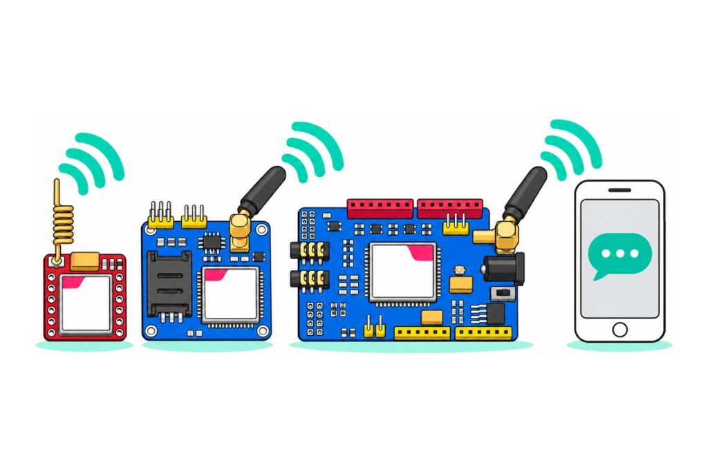
The SIM800L, SIM900A and SIM900 shield carry nearly the same 2G radio chip from SIMCom. The board around it differs, and that decides how you power and wire it.
| SIM800L | SIM900A | SIM900 shield | |
|---|---|---|---|
| What it is | Bare red core board, about 2.5 x 2.3 cm | Blue carrier board, about 5 x 5 cm (printed SIM900A MINI) | Blue Arduino Uno shield, the size of an Uno (sold as the SIM900 module) |
| Supply you give it | 3.4 to 4.4V straight to VCC (one Li-ion cell) | 5V on the VCC5 pin | 5V 2A adapter in its own DC jack |
| Peak current | Up to 2A in bursts | Up to 2A in bursts | Up to 2A in bursts |
| Serial pins | 2.8V logic. Needs a resistor divider on RXD | Two pairs: 5VT/5VR for a 5V board, 3VT/3VR for a 3.3V board | Through the Uno’s headers, on D7 and D8 |
| Soldering | 12 header pins and the antenna | None | None |
| Antenna | Gold spring coil, soldered to the NET pad | Black stub on a gold SMA socket | Black stub that screws onto a gold SMA socket |
| SIM size | Micro-SIM | Full-size SIM | Full-size SIM |
| GSM bands | 850, 900, 1800, 1900 MHz | 900, 1800 MHz | 850, 900, 1800, 1900 MHz |
| Switching on | No button. Starts when power is connected | No button. Starts when power is connected | Hold the PWRKEY button about 2 seconds |
| Works with | Uno or ESP32 | Uno or ESP32 | Uno (it stacks on the Uno’s headers) |
Parts you need
The SIM900 shield needs an Uno and the 5V 2A adapter, which has the 3-pin plug for Malaysian 230V sockets. If the shield’s yellow serial pins have no jumper caps, add two female-to-female jumpers. The SIM900A needs male-to-female jumpers and its own 5V 2A supply. The SIM800L also needs a breadboard, jumpers, resistors and soldering: the full list is in our SIM800L first SMS guide.
GSM modules: pick one
 SIM800L GSM GPRS Module Quad-Band Network Development Board TTL Port for Arduino Raspberry Pi DIY Projects
 SIM900A GSM Sim Module GPRS Wireless Module with Antenna Sim Card SMS CALL Ring Call
 SIM900 Module GSM GPRS Module Dual Band GSM Module
What each module needs beside it
 Arduino Uno Compatible SMD UNO R3 with Type B Cable - ATMEGA328P with CH340G-Microcontroller Project
 Power Supply Adapter DC Universal AC to DC Converter PSU 5V2A 5V3A 9V2A 12V2A - P.S. ADAPTOR (5V2A)
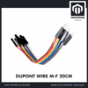 40pcs Dupont Wire 10cm 20cm 30cm for Breadboard DIY Experiment Jumper Wire Breadboard wire - DUPONT WIRE M-F 20CM
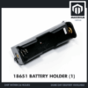 18650 Battery Holder 1/2/3/4 Slot 3.7V Battery Cell Housing Battery Case Battery Casing - 18650 BATTERY HOLDER (1)
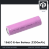 3.7V 18650 Battery Rechargeable Li-Ion Battery 1200mAh 2200mAh 3200mAh Flat Top - 18650 Li-Ion Battery (2200mAh)
The Uno works with all three. The 5V 2A adapter plugs straight into the SIM900 shield's DC jack. The M-F jumpers fit the SIM900A's header pins, and its 5V supply is covered in the wiring section. The 18650 cell and holder power the SIM800L.
What power supply does each GSM module need?
A GSM module such as the SIM800L or SIM900 transmits in bursts. Eight phones share one 2G channel and take turns, so each sends for one 577 microsecond slot in every 4.615 millisecond frame (SIM800L hardware guide). In that slot the radio puts out up to 2W. At about 4V, 2W is already 0.5A (2 ÷ 4). The amplifier also loses part of what it draws as heat, so SIMCom tells designers to provide up to 2A.
A multimeter sees nothing wrong, because it shows an average a few times a second and each burst lasts about half a millisecond. A weak supply still fails: its voltage dips inside each burst, and at 2A every 0.1 ohm of wire, contact or supply loses 0.2V. Below SIMCom’s power-down level (3.0 to 3.4V, depending on the chip) the module shuts down. The SIM800L and SIM900A restart by themselves. The SIM900 shield stays off until you press PWRKEY.
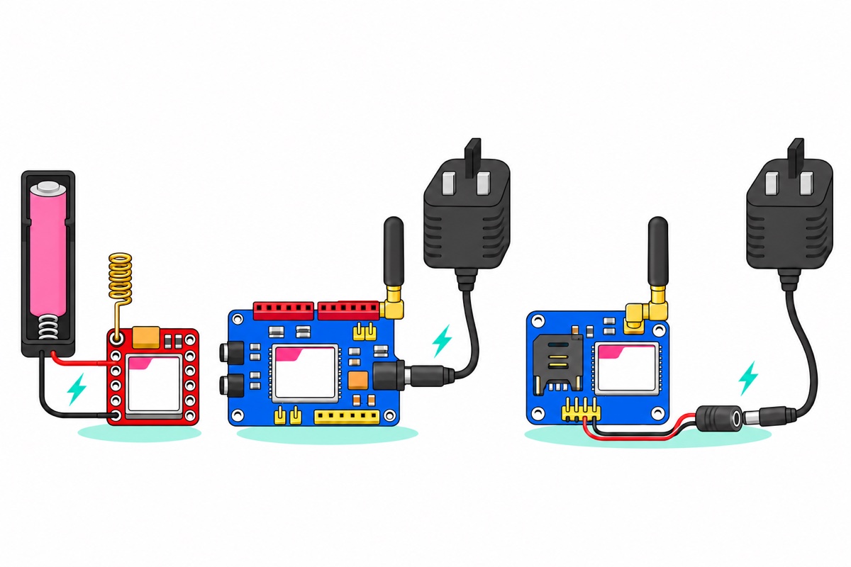
On USB power the Uno’s 5V pin has at most 500mA to give (the USB 2.0 limit), a quarter of a 2A burst. Powered from its DC jack, the Uno’s 5V pin comes through a 1A regulator, still short of 2A. Each board has its own route from a strong supply to the chip’s roughly 4V.
| Board | Supply | How it reaches the chip |
|---|---|---|
| SIM800L | One 18650 Li-ion cell in a holder (how to charge it safely) | No regulator. VCC goes straight to the chip, so the supply itself must be 3.4 to 4.4V. A Li-ion cell is 4.2V full and about 3.7V for most of its charge. 5V is over the limit. If the module keeps restarting, see the SIM800L brownout guide |
| SIM900 shield | 5V 2A adapter in the DC jack | A regulator beside the jack. SIMCom’s 5V reference design regulates down to 4.1V (SIM900 hardware guide), and the shield’s silkscreen marks the same 4.1V. Slide the switch by the jack to EXTERN, so power comes from the jack. The other position takes power from the Uno’s 5V pin, which cannot supply the bursts |
| SIM900A | Your own 5V 2A supply on VCC5 | Feed it exactly 5V, as the pin name says. The chip itself is rated only 3.4 to 4.5V (SIM900A datasheet) and the board is built to bring 5V into that range. Never give it 9V or 12V |
Pick by your project
| Your project | Pick | Why |
|---|---|---|
| SMS alarm on an Uno (a gas, flood or intruder alert for school or FYP) | SIM900 shield | Nothing to solder, one adapter |
| Battery powered or small, such as a GPS tracker | SIM800L | Runs from one 18650 cell |
| ESP32 (ESP32 or Uno?) | SIM800L or SIM900A | The shield is made to stack on an Uno |
| A project box that already has a 5V 2A rail | SIM900A | Header pins and antenna are fitted |
Wiring to an Arduino Uno or ESP32
Fit the antenna on the SIM800L, SIM900A or SIM900 shield before you connect power. With no antenna, the transmit power reflects back into the module and can damage its output amplifier.
SIM900 shield on an Uno
| Step | What to do |
|---|---|
| SIM | Open the black flip-up holder under the shield and fit a full-size SIM before stacking |
| Antenna | Clip the free end of the thin black cable onto the tiny gold socket marked ANT. Screw the black stub antenna onto the gold SMA socket |
| Serial pins | Find the yellow block of six pins beside the SMA socket. The middle pin of each row is the SIM900. Join each middle pin to the pin on the side printed D7(TX) and D8(RX), with a jumper cap or a short female-to-female jumper. The other side, D0 and D1, is the Uno’s USB serial port, which uploads and the Serial Monitor need |
| Stack | Press the shield onto the Uno with every pin in its socket. This also joins the two grounds. A strip of insulating tape on top of the Uno’s metal USB socket stops it touching the solder joints under the shield |
| Power | 5V 2A adapter into the shield’s DC jack, slide switch at EXTERN. Power the Uno by USB as usual |
| Switch on | Hold the small PWRKEY button on the edge for about 2 seconds until the Status LED lights. The same press switches it off |
SIM900A
Wire the SIM900A by the label printed beside each pin. If the antenna hides the labels, unscrew it to read them.
| SIM900A pin | Arduino Uno | ESP32 |
|---|---|---|
| VCC5 and GND (six-pin block) | Plus and minus of your 5V 2A supply, through two male-to-female jumpers (jumper types). No soldering: plug the 5V 2A adapter into a female DC barrel pigtail, twist each bare lead tightly around a jumper’s pin, then tape each joint so the two cannot touch. The red lead is plus (the adapter is centre-positive) and goes to VCC5, the black lead to GND. Check the polarity with a multimeter before the jumpers go on the board. Soldered: an LM2596 buck converter fed from 9 to 12V and set to 5.0V before you connect it (LM2596 guide) | |
| GND (three-pin header) | Uno GND | ESP32 GND |
| 5VT (the module transmits here) | Uno D2, direct. This pair is already 5V logic, so no resistors | Leave free |
| 5VR (the module receives here) | Uno D3, direct | Leave free |
| 3VT | Leave free | GPIO16 (printed RX2 or D16) |
| 3VR | Leave free | GPIO17 (printed TX2 or D17) |
| DB9-2 and DB9-3 | Never connect these. They carry RS232 signals from the black MAX232 chip, which swing several volts above and below 0V and can damage an Arduino or ESP32 pin | |
SIM800L
The SIM800L’s RXD pin reads a HIGH between 2.1 and 3.0V, because its logic runs on a 2.8V rail. An Uno’s 5V and an ESP32’s 3.3V are both too high, so each passes through a divider: two resistors in a chain that share the voltage in proportion to their values. The Uno’s 10k pair would give an ESP32 only 1.65V, below 2.1V, so the ESP32 gets a different pair.
The 18650 is an unprotected cell: nothing inside cuts off a short, so never let the holder’s bare leads touch. Check the polarity twice, because the SIM800L has no reverse protection.
| SIM800L pin | Arduino Uno | ESP32 |
|---|---|---|
| VCC | 18650 holder, red lead | 18650 holder, red lead. Never the ESP32’s 3V3 pin: 3.3V is under the 3.4V minimum, and its small regulator cannot give 2A bursts |
| GND | Holder black lead and Uno GND | Holder black lead and ESP32 GND |
| TXD | Uno D2 | GPIO16 (printed RX2 or D16) |
| RXD | Uno D3 through 10k, and 10k from RXD to GND. 5V × 10 ÷ 20 = 2.5V | GPIO17 (printed TX2 or D17) through two 1k in series, and 10k from RXD to GND. 3.3V × 10 ÷ 12 = 2.75V |
| NET | The gold spring antenna, soldered (soldering guide) | |
First test: one sketch, three AT commands
This sketch tests a SIM800L, SIM900A or SIM900 shield. Set RX_PIN and TX_PIN for your board first.
// First test for a SIM800L, SIM900A or SIM900 shield.
// It passes what you type in the Serial Monitor to the module
// and prints every reply.
// Serial Monitor: 9600 baud, line ending "Both NL & CR".

// Set the two pins for your board:
//   SIM800L or SIM900A on an Uno:    RX_PIN 2,  TX_PIN 3
//   SIM900 shield on an Uno:         RX_PIN 7,  TX_PIN 8
//   SIM800L or SIM900A on an ESP32:  RX_PIN 16, TX_PIN 17
const int RX_PIN = 2;        // receives from the module's TX pin
const int TX_PIN = 3;        // sends to the module's RX pin
const long GSM_BAUD = 9600;  // no reply to AT? try 19200

#if defined(ESP32)
HardwareSerial &gsm = Serial2;       // the ESP32 has a spare hardware port
#else
#include <SoftwareSerial.h>
SoftwareSerial gsm(RX_PIN, TX_PIN);  // the Uno's hardware port is busy with USB
#endif

void setup() {
  Serial.begin(9600);
#if defined(ESP32)
  gsm.begin(GSM_BAUD, SERIAL_8N1, RX_PIN, TX_PIN);
#else
  gsm.begin(GSM_BAUD);
#endif
}

void loop() {
  if (gsm.available()) Serial.write(gsm.read());
  if (Serial.available()) gsm.write(Serial.read());
}
- Power the module and watch its blinking network LED (marked NetLight on the shield). About one flash a second means searching. One every 3 seconds means registered.
- Open the Serial Monitor at 9600 baud, line ending “Both NL & CR”. The module acts only when the carriage return arrives.
- Type
ATand press Enter a few times. The module works out your baud rate from theseATs, so the first may get no reply. A saved fixed rate switches that off, and a silent SIM900 shield may have 19200 saved: changeGSM_BAUDto 19200 and upload again.
| Command | Good reply | Anything else means |
|---|---|---|
AT |
OK |
Silence: TX and RX swapped, no shared GND, no power, or the shield is not switched on |
AT+CPIN? |
+CPIN: READY |
+CPIN: SIM PIN: the PIN lock is still on. ERROR or +CME ERROR: 10: the SIM is not detected, so reseat it |
AT+CREG? |
+CREG: 0,1 (home) or 0,5 (roaming) |
0,2: still searching, so wait and check the antenna. 0,3: the network refused the SIM. If either stays, check that the SIM’s operator runs 2G (next section) and that the prepaid line is active |
Three good replies? Follow the SMS steps in the first SMS guide. On an Uno, change only its pin numbers (and its baud, if yours needed 19200). On an ESP32 its sketch will not compile, because the ESP32 core has no SoftwareSerial library. Use HardwareSerial &sim800 = Serial2; and sim800.begin(9600, SERIAL_8N1, 16, 17); in place of its #include, SoftwareSerial and sim800.begin lines.
Does 2G still work in Malaysia?
Yes. The SIM800L, SIM900A and SIM900 are 2G-only radios, and 2G is on air in Malaysia. Operators switched off 3G by the end of 2021 and kept 2G for basic phones and machine-to-machine devices. CelcomDigi’s help page says it has no plans to shut 2G down, and TM’s roaming agreement with Maxis gives TM access to Maxis’s 2G and 4G network until 30 September 2029. No operator has published a switch-off date. Check with the operator before a multi-year deployment.
A SIM card is only an identity card. It tells the network who you are. The radio decides which network it can hear, and these three hear only GSM (2G). So a SIM sold as 4G or 5G works in them whenever its operator still broadcasts 2G. On a 4G-only network the module finds nothing to join.
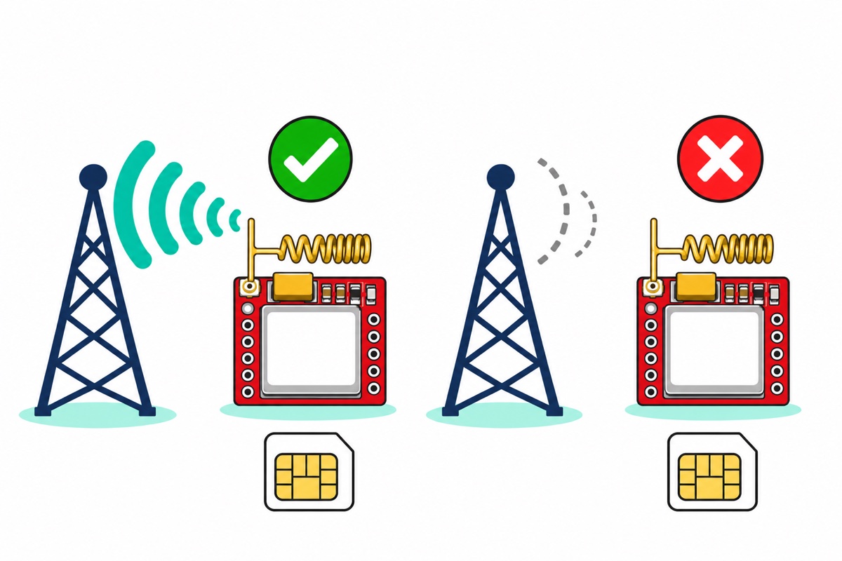
All three cover Malaysia’s GSM bands, 900 and 1800 MHz. The extra 850 and 1900 MHz of the quad-band SIM800L and SIM900 are used in the Americas, so in Malaysia the dual-band SIM900A loses nothing.
SIM card checklist
- Operator: Maxis (Hotlink) and CelcomDigi (Celcom, Digi) run 2G. For other brands, ask whether the SIM works in a 2G-only phone.
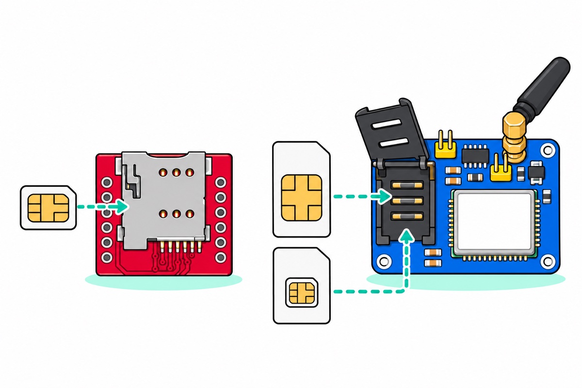
- Size: micro-SIM for the SIM800L, full-size SIM for the other two. A nano-SIM goes in its adapter frame.
- PIN lock: switch it off in a phone first.
- Credit and validity: an expired prepaid line stops your alerts without warning. Send one SMS from a phone first.
- Plain text only: on MCMC’s instruction, operators block SMS containing a web link, a phone number or personal details (CelcomDigi notice), and the module can still report the message as sent. A GPS tracker should text its coordinates as numbers, never as a map link.
FAQ
Can I power a SIM800L or SIM900A from the Arduino’s 5V pin?
No. A GSM module draws bursts of up to 2A, and on USB power the Uno’s 5V pin has about 500mA. The voltage dips and the module restarts. 5V is also above the SIM800L’s 4.4V limit.
Can I use a 4G or 5G SIM card in a SIM800L or SIM900A?
Yes, if the operator behind the SIM still runs 2G. The module’s radio is 2G-only and the SIM only identifies you. In Malaysia, Maxis and CelcomDigi run 2G.
Why does my SIM900 shield not answer AT commands?
The shield starts switched off. After every power-up, hold PWRKEY about 2 seconds until the Status LED lights. Then check the serial pins are joined on the D7 and D8 side, and try 19200 baud.
Last updated November 2026. Stuck? Chat with us on WhatsApp.
