

Tutorials
USB to RS485 Converter (CH340): Wire A/B and Read a Modbus Sensor on a PC
Nov
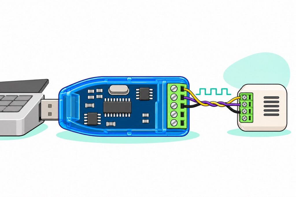
Quick answer: wire A to A and B to B, then poll the device with a free Modbus tool.
- Plug the adapter in. Device Manager must list USB-SERIAL CH340 with a COM number. If not, install the CH341SER driver from WCH.
- Wire A to the device’s A (or A+, D+), B to B (B-, D-) and GND to its GND or common. A sensor that accepts 5V can run from +5V and GND.
- In OpenModScan choose Connection, Connect, “Direct Connection to Serial Port”, your COM port, and the device’s baud rate and parity (often 9600, 8, NONE, 1).
- Set Address Base to 0-based, then Device ID, point type (03 or 04), Start Address and Length from the manual.
- No reply (“No Responses from Slave Device”)? Swap A and B first, then check baud and ID. “ILLEGAL DATA ADDRESS” means the wiring is right: check the address and Length, then try the other point type.
Which USB to RS485 adapter: 5-terminal or 2-terminal
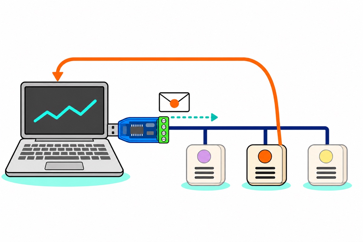
A USB to RS485 adapter shows up on the PC as a COM port. What a program sends to that port goes out on two wires, A and B, and the reply returns on the same pair.
| 5-terminal CH340 adapter | 2-terminal dongle | |
|---|---|---|
| How to spot it | See-through blue shell, green 5-way screw terminal | Matte black shell, green 2-way screw terminal |
| Terminals | A, B, GND, GND, +5V | A and B only |
| Ground wire to the device | Yes, either GND terminal | No. Fine for the two-adapter test (both share the PC’s ground through USB) and for devices with only A and B. A device on its own supply that has a GND or COM terminal belongs on the 5-terminal adapter (why: the GND row in Step 2) |
| 5V for a small sensor | Yes, from +5V and GND | No |
| Chips | CH340G (USB to serial) and MAX485 (RS485 transceiver). Both ends talk on the same two wires, so only one may drive them at a time: the board turns the MAX485’s transmitter on while the PC sends and back to listening when it stops. The Modbus tool needs no RTS or direction setting | A USB-to-serial chip and an RS485 transceiver in a sealed case. Find its COM number in Device Manager the same way (Step 1). If it shows with a yellow warning mark instead of under Ports (COM & LPT), right-click it, Properties, Details, Hardware Ids: VID_1A86 is WCH, VID_10C4 Silicon Labs, VID_0403 FTDI, VID_067B Prolific. Install the driver from that chip maker’s site |
| Speed | The CH340 handles 50 bps to 2 Mbps (WCH datasheet) and the MAX485 up to 2.5 Mbps (Maxim datasheet). Modbus devices use 1200 to 115200 baud (most often 9600 or 19200), all well inside both | Used at the same Modbus baud rates |
| Which screw is A | Printed on the underside of the board (Step 2) | Use the swap test below: if the device stays silent, exchange the two wires |
| Pick it for | A first adapter. It covers every setup on this page | A second adapter for the no-sensor test, or a device with only A and B terminals |
USB to RS485 adapter and jumper wires
 USB to RS485 Serial Converter Adapter Module CH340 Chipset for Industrial Communication
 40pcs Dupont Wire 10cm 20cm 30cm for Breadboard DIY Experiment Jumper Wire Breadboard wire - DUPONT WIRE M-M 20CM
Parts list
 USB to RS485 Serial Converter Adapter Dongle Module for PC Industrial Communication
 XL830L Digital Multimeter with backlight Portable Multimeter Electronics Project
The 2-terminal dongle is the second adapter for the no-sensor test. The multimeter checks the +5V terminal and the polarity of an external supply before a sensor is connected.
You also need the RS485 device and a small flat-blade screwdriver. Male-to-male jumper pins clamp straight into screw terminals. Beyond a couple of metres, use a twisted pair for A and B (one pair from a Cat5e network cable) and a spare wire of that cable for GND.
Step 1: Install the CH340 driver
The adapter’s CH340G chip takes the same driver as many Arduino-compatible boards.
- Plug the adapter in and open Device Manager (right-click the Start button).
- Under Ports (COM & LPT), find USB-SERIAL CH340 (COMx) and note the number.
- If it is missing, install CH341SER from WCH, then replug.
- Unplug the adapter to confirm: its entry vanishes, then returns on replug (more in our Arduino Nano guide).
Step 2: Wire A, B and GND
The 5-terminal adapter’s labels are printed on the underside of the board only. Turn it label side up, terminals towards you, and read them through the blue shell: A, B, GND, GND, +5V from left to right. Turn it over to tighten the screws, terminals still towards you, and the order mirrors: A is the right-most screw.
| Adapter terminal | Device terminal (names you may see) | What it does |
|---|---|---|
| A | A, A+, D+, D1, T/R+ | The + line of the data pair |
| B | B, B-, D-, D0, T/R- | The – line of the data pair |
| GND (either one) | GND, COM, SG, or the device supply’s 0V | Gives both ends the same 0V. The receiver chip measures A and B against its own ground and accepts them only from -7V to +12V around it (MAX485 datasheet). A device on a separate supply with no shared 0V can drift outside that window, so connect GND whenever the device has its own supply. The adapter is not isolated: this wire joins the PC’s ground to the device’s ground. That is fine on a bench. In a plant, earth points far apart can sit volts apart, and this wire would carry that difference as current through the PC, so long earth runs need an isolated adapter |
| +5V | V+ or VCC of a small sensor that accepts 5V | An output: the PC’s USB 5V rail brought out to a screw. Leave it empty when the device has its own supply, because a second supply on it would push current back into the laptop’s USB port |
Keep these terminals low-voltage. Never connect mains, 12V or 24V to A, B or +5V (A and B survive -8V to +12.5V at most, MAX485 datasheet), and never feed a supply into +5V. Energy meters, inverters and VFDs have 230V terminals beside the RS485 pair: switch the mains off first and leave the mains side to a competent person.
| Sensor | Power it from | How |
|---|---|---|
| Accepts 5V. The example sensor below takes DC 4 to 30V and at most 0.2W, which at 5V is 0.2 ÷ 5 = 0.04A (40mA), a light load for a USB port | The adapter’s +5V and GND terminals | Check first with a multimeter: +5V to GND should read about 5V (how to measure DC voltage) |
| Needs more than 5V and accepts 12V (for example a 10 to 30V sensor) | A 12V adapter (its 3-pin plug fits Malaysian sockets) and a female DC socket lead, which turns the barrel plug into a red and a black wire (barrel plugs explained) | Red to the sensor’s V+. Black to the sensor’s V- and to the adapter’s second GND terminal. Confirm which lead is positive with the multimeter before connecting, and cover twisted joints with insulation tape |
Why does swapping A and B fix so many RS485 faults?
RS485 sends each bit as the voltage difference between wires A and B. For a 1 the driver pushes A above B, and for a 0 it pushes B above A. The MAX485 receiver subtracts B from A: above +0.2V is a 1, below -0.2V is a 0 (MAX485 datasheet). Twisting the pair makes noise land on both wires equally, so it cancels in the subtraction.
Swap the wires and every difference changes sign, so each 1 arrives as a 0. The device receives garbage that fails its checksum, so it stays silent. Nothing is damaged: each pin still sees the same voltages as before, only at opposite moments, so a swap is a safe first test.
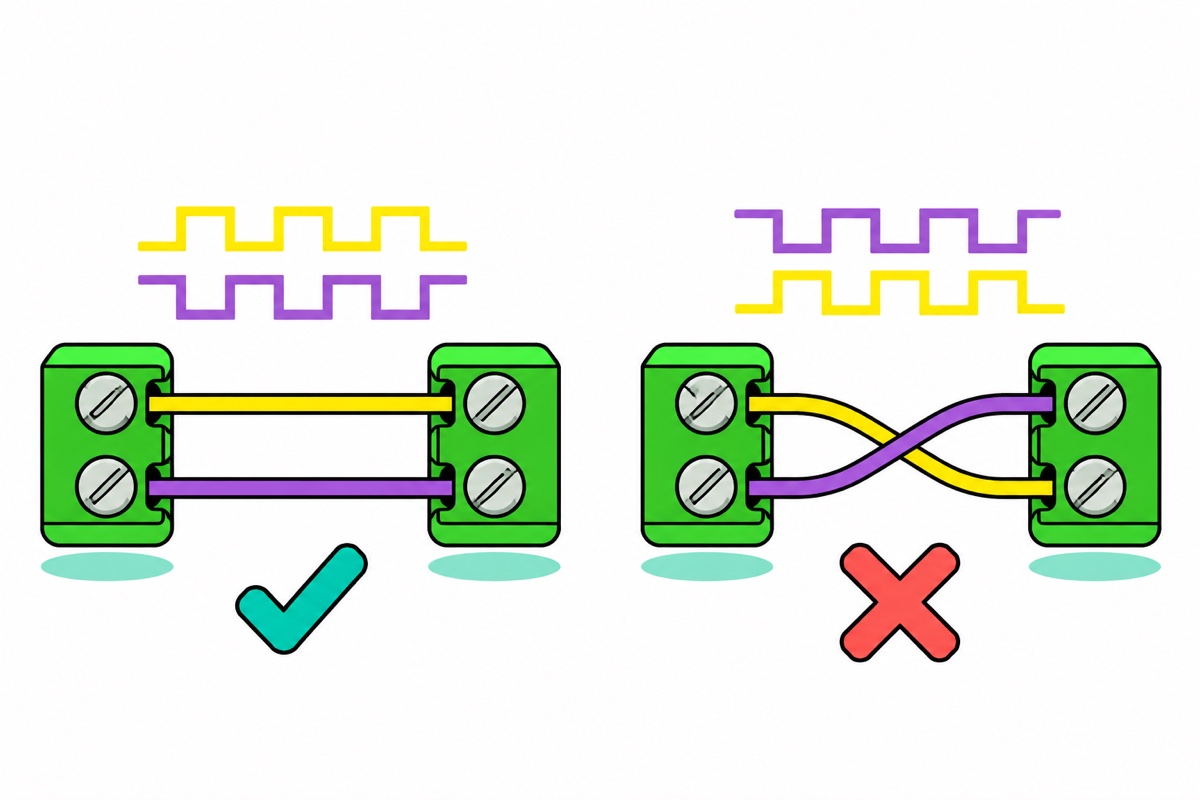
The swap is common because the names disagree. The MAX485 datasheet calls its non-inverting (+) line A, while the Modbus serial line specification gives the + line (D1) the TIA-485 letter B. On this adapter A is +, so match + to A and – to B.
Do you need a 120 ohm termination resistor?
A 120 ohm termination resistor is not needed on a short bench lead. An open cable end bounces the signal back as an echo. A resistor matching the cable’s impedance (100 to 120 ohms) absorbs it. A signal edge covers a metre of typical RS485 cable in about 4.3ns (1.3ns per foot in the TI RS-485 design guide), so on a 1m lead the echo returns in about 9ns. One bit at 9600 baud lasts 1 ÷ 9600 of a second, about 104,000ns, so the echo dies long before the bit is read.
On a long cable at a high baud rate, echoes land inside later bits. Then fit one resistor across A and B at each end of the bus, never more than two (Modbus specification), since each one also loads the driver. Use 120 ohm to match standard RS485 cable (TI guide).
Step 3: Read a Modbus register with OpenModScan
Modbus RTU is question and answer: the PC (master) sends a request, and the one device (slave) whose ID matches replies. A request needs four values from the device manual. The example is a common SHT20 temperature and humidity transmitter, the XY-MD02 (manual).
| Value from the manual | Field in OpenModScan | XY-MD02 example |
|---|---|---|
| Serial settings | Baud Rate, Word Length, Parity, Stop Bits | 9600, 8, NONE, 1 |
| Slave address | Device ID | 1 |
| Function code | MODBUS Point Type | 04: INPUT REGISTER |
| Register address | Address Base, Start Address, Length | 0-based, 1, 1 |
- Install OpenModScan, a free open-source Modbus master for Windows.
- Choose Connection, Connect. Set Connect Using to “Direct Connection to Serial Port”, pick your COM number, set Baud Rate, Word Length, Parity and Stop Bits, then OK.
- Set Address Base to 0-based first, then Device ID 1, MODBUS Point Type 04: INPUT REGISTER, Start Address 1 and Length 1.
- Number of Polls and Valid Slave Responses should climb together, and the register shows a value such as 305.
What went over the wires:
| Bytes (hex) | Meaning |
|---|---|
| Request: 01 | Device ID 1 |
| 04 | Function 04, read input registers |
| 00 01 | Start at address 1 |
| 00 01 | Read 1 register |
| 60 0A | CRC checksum, worked out by the tool |
| Reply: 01 04 02 | Device 1, function 04, 2 data bytes follow |
| 01 31 | The reading. Hex 0131 is 1 × 256 + 3 × 16 + 1 = 305. The manual says to divide by 10, so 305 is 30.5°C |
| 79 74 | CRC checksum from the sensor |
| Setting | What it means | For the XY-MD02 |
|---|---|---|
| MODBUS Point Type (the function code) | Function 03 reads holding registers: settings that can also be written. Function 04 reads input registers: read-only measurements | Readings are on 04. Its own address (0x0101) and baud rate (0x0102) are on 03. Many meters put their readings on 03, so follow the manual |
| Address Base | On the wire, Modbus addresses count from 0, but some manuals and tools count from 1. In 1-based mode, which is how OpenModScan starts, the tool subtracts 1 from the number you type before sending it. Some manuals print 5-digit numbers such as 30001 or 40001: the first digit names the table (3 = input register, function 04; 4 = holding register, function 03) and the rest counts from 1, so 40001 is address 0 on the wire (type 0 in 0-based mode) | The manual prints the on-the-wire address (0x0001), so choose 0-based and type 1. Type addresses in decimal: 0x0101 is 1 × 256 + 1 = 257 |
Timeout or exception code: what the reply tells you
A Modbus slave answers only when a request arrives intact, passes the checksum and carries its own ID. Swapped A and B, a wrong baud rate or parity, or another device’s ID all fail that test, so silence points at the wiring, the serial settings or the Device ID.
If the request passes but asks for something the device lacks, the slave replies with an exception code. Any reply, even an error, proves the wiring, COM port, baud rate, parity and ID are right.
| OpenModScan shows | What it means | What to check |
|---|---|---|
| Device NOT CONNECTED! | The COM port is not open | Connection, Connect. Only one program can hold a COM port, so close the Arduino Serial Monitor or any other serial tool. A different USB socket can give the adapter a new COM number, so check Device Manager again |
| No Responses from Slave Device. Valid Slave Responses stays at 0 | The request went out and nothing valid came back | In this order: swap A and B, the COM number, baud rate and parity, Device ID, the device’s power, the GND wire. The Modbus specification’s default is 19200 baud with even parity, yet many small sensors ship at 9600 with no parity, so the manual or the device label decides. If the ID or baud rate is unknown, the MODBUS Scanner tool in the menus tries a range of both |
| ILLEGAL FUNCTION (0x01) | The device answered. It does not support that function | Switch between 03 and 04 |
| ILLEGAL DATA ADDRESS (0x02) | The device answered. It has no register at that address | The 0-based or 1-based setting, hex converted to decimal, a 30001 or 40001 number typed in full, a shorter Length. Then try the other point type: a device that supports both 03 and 04 answers 0x02 when the register sits in the other table |
| A reading from the wrong register | The address is off by one | Address Base |
No sensor yet: test with two adapters
Plug the 5-terminal USB to RS485 adapter and the 2-terminal dongle into one PC. Each gets its own COM number (unplug one to see which is which). Wire the adapter’s A and B to the dongle’s two screws in either order. No GND wire is needed: USB already joins both grounds.
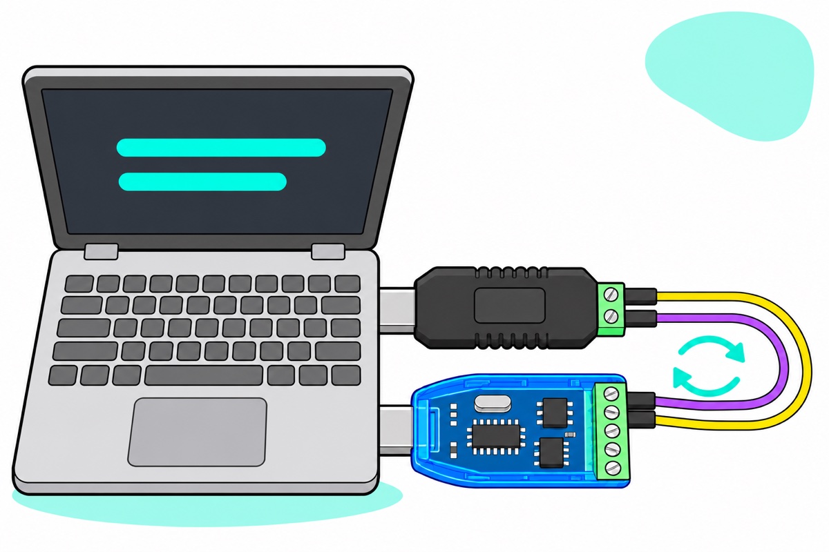
On the first COM port, run a Modbus slave simulator such as the free OpenModSim as an RTU slave with ID 1, and put a number in holding register 1. Poll it from OpenModScan on the second COM port with 03: HOLDING REGISTER, Start Address 1 and the same serial settings. Set Address Base back to 1-based to match OpenModSim, or you read the register beside yours. Your number appearing proves the driver and the settings. A timeout means swap the two wires at the dongle.
Next step: RS485 on an Arduino or ESP32
A TTL-to-RS485 module does for a microcontroller what this adapter does for a PC. The common MAX485 module is a 5V part that suits an Arduino Uno: DI takes the board’s TX, RO feeds its RX, and DE and RE share one GPIO. DE enables the transmitter when HIGH and RE enables the receiver when LOW, so HIGH sends and LOW listens. On an Uno, RO on pin 0 fights the USB chip during uploads, so unplug it while uploading or use SoftwareSerial pins. An ESP32 runs at 3.3V, so use a 3.3V transceiver (MAX3485 type): a 5V MAX485 would feed nearly 5V into its RX pin.
The ModbusMaster library builds the same requests from the four values you proved on the PC, a solid first milestone for a final-year project.
FAQ
Which wire is A and which is B on RS485?
On this adapter A is the + line (A+, D+) and B is the – line (B-, D-). Manufacturers use the letters differently, so if the device stays silent, swap the two wires. A swap damages nothing.
Can a USB to RS485 adapter power my sensor?
Only the 5-terminal adapter: its +5V terminal passes on the PC’s USB 5V for a small sensor that accepts 5V. Never connect a supply to that terminal.
How many devices can share one RS485 bus?
The Modbus serial line specification allows 32 devices without a repeater, on up to 1000m of cable at 9600 baud. Each device needs its own ID from 1 to 247.
Last updated November 2026. Stuck? Chat with us on WhatsApp.
