

Tutorials
ISD1820 vs JQ8900 vs DFPlayer Mini: Which Sound Module, Wiring and Code
Nov
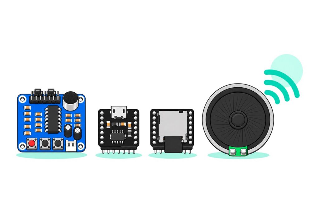
Quick answer: Pick by where the sound comes from. All three run on 5V from an Arduino.
- Your own voice, up to 10 seconds, no computer and no code: ISD1820, speaker included (solder its loose lead on first). Hold REC and speak, then press PLAYE.
- A few fixed prompts or sound effects, no memory card: JQ8900. Copy MP3 files to it over micro-USB (about 4 minutes in total). Play by serial command or by touching IO1 to GND.
- Many tracks or long audio: DFPlayer Mini with a microSD card up to 32GB (FAT32).
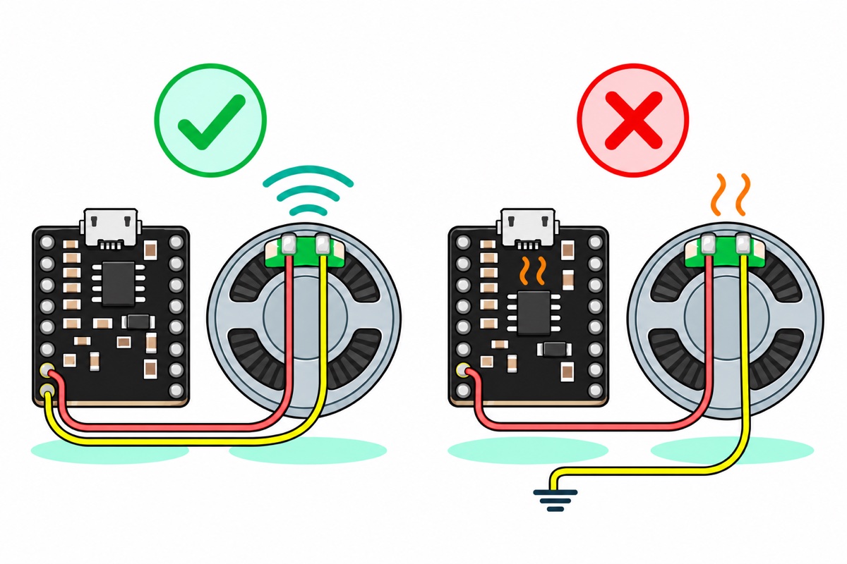
- Connect an 8 ohm speaker across the two speaker pins. Never connect either speaker pin to GND.
ISD1820 vs JQ8900 vs DFPlayer Mini at a glance
The ISD1820, JQ8900 and DFPlayer Mini all play a stored sound through a small speaker. Where the sound is stored decides how long it can be and how you load it.
| ISD1820 | JQ8900 (JQ8900-16P) | DFPlayer Mini (MP3-TF-16P) | |
|---|---|---|---|
| Where the sound is stored | Inside the chip, as one analogue recording | A 4MB flash chip on the board | A microSD card that you add, up to 32GB |
| How the sound gets in | Speak into the on-board mic | Copy MP3 or WAV files from a computer over micro-USB | Copy MP3 or WAV files to the card on a computer |
| How much it holds | One message, 10 seconds. A new recording replaces it, and it stays without power | About 4 minutes at 128 kbps, shared by all files | Hours. The card is the limit |
| Play with no code | Press PLAYE or PLAYL | Touch IO1 to IO7 to GND, one file per pin | Touch IO_2 to GND for the next track |
| Arduino control | One digital pin, a short HIGH pulse | Serial at 9600 baud, a few bytes per command | Serial at 9600 baud, with a library |
| Supply | 3 to 5V | 3.6 to 5.2V | 3.2 to 5V |
| Amplifier power into 8 ohm | Tens of milliwatts | About 1.3W | About 1.3W |
| In the box | Board, 8 ohm 0.5W speaker, loose speaker lead (two joints to solder) | Board with header pins fitted. No speaker | Board with header pins fitted. No speaker, no card |
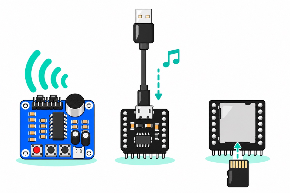
For a school project that speaks one line (a smart dustbin that says “terima kasih”), the ISD1820 is the short route: record it on the spot, in any language.
These modules only play. For spoken commands, see the ZK-VR01 voice control relay. For audio that an ESP32 generates or streams, see the MAX98357A I2S amplifier.
Parts you need
The ISD1820, JQ8900 and DFPlayer Mini are alternatives, so buy one.
The three sound modules (pick one) and a speaker
 ISD1820 Voice Recording Module Sound Playback Board Audio Recording Module DIY Electronic Kit 10s Record Time
 JQ8900 MP3 Sound Module Serial UART Control Voice Audio Player Module for Arduino DIY Projects
 Mini MP3 Player Module DFPlayer Music Sound Module Arduino Compatible
 8 Ohm 0.5W Mini Speaker Small Round Audio Speaker for Arduino DIY Projects Electronic Components Sound Module
Parts list
 Arduino Uno Compatible SMD UNO R3 with Type B Cable - ATMEGA328P with CH340G-Microcontroller Project
 MB102 Breadboard 170 400 830 Holes Breadboard Donut Board Arduino Prototype Multi Color - BREADBOARD (400 HOLES)
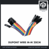 40pcs Dupont Wire 10cm 20cm 30cm for Breadboard DIY Experiment Jumper Wire Breadboard wire - DUPONT WIRE M-M 20CM
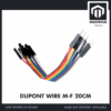 40pcs Dupont Wire 10cm 20cm 30cm for Breadboard DIY Experiment Jumper Wire Breadboard wire - DUPONT WIRE M-F 20CM
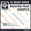 400 pcs 1/4W Resistor Pack Resistor Kit 20 Common Value with 20 each
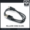 Data Cable Type-A Type-C MicroUSB Type-B 0.5m 1m 30cm 0.3m 100cm Data Transfer Upload Code - MicroUSB CABLE (0.5M)
 Soldering Service for Circuit Boards & Electronics - 1 Pin Soldering Service
The Uno, breadboard, jumpers and resistors are only for the Arduino-triggered versions. The micro-USB data cable loads MP3s into the JQ8900. The 2 soldering-service pins cover the ISD1820 speaker lead.
Neither MP3 module includes a speaker. Add an 8 ohm 0.5W speaker, or use any 4 to 8 ohm speaker from an old toy or radio. The DFPlayer also needs a microSD card of up to 32GB.
Plan for two solder joints: the ISD1820’s lead onto its speaker, or two wires onto a loose speaker’s bare pads (soldering guide). With no iron, two units of the 1-pin soldering service cover the ISD1820 lead.
For the Arduino versions, the MP3 modules plug into a breadboard and use male-to-male jumpers. The ISD1820’s pins point up, so it takes male-to-female jumpers.
ISD1820: record 10 seconds with the on-board mic
The ISD1820 keeps one message inside its chip, in a fixed number of storage cells that each hold one sample of the sound. A resistor sets the samples per second. On this board that is R4, marked 104 (10 and four zeros: 100k), which the ISD1800 family datasheet lists as 6,400 samples a second for 10 seconds, so it has about 64,000 cells. A bigger resistor slows the sampling, so the same cells last longer, but sound is only captured below half the sampling rate. The same datasheet puts the chip’s filter cut-off at 2.2kHz with 100k: clear for speech, thin for music.
- Solder the lead’s two bare ends to the two pads on the speaker’s green strip, either way round, and push the white plug into SP1.
- Connect VCC and GND to 3 to 5V, such as the Uno’s 5V and GND pins, or two AA cells (3V).
- Hold the red REC button and speak towards the mic, then let go. The LED stays on while it records.
- Press PLAYE once for the whole message. PLAYL plays only while held.
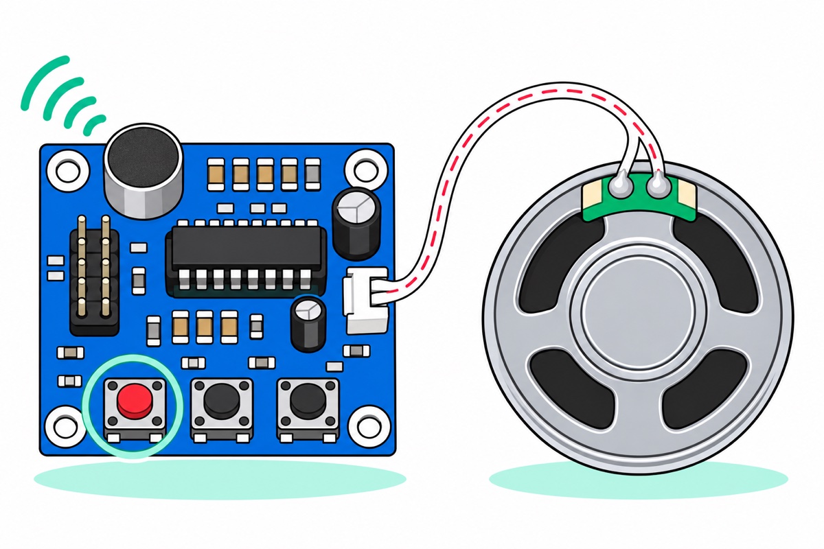
From an Arduino, one pin does the pressing. PLAYE starts on a LOW-to-HIGH edge and has a pull-down inside the chip (module guide), so an Uno pin drives it directly with no resistor.
| ISD1820 header (the six pins beside the printed labels) | Connect to |
|---|---|
| VCC | Uno 5V |
| GND | Uno GND |
| P-E | Uno D7. While it is wired, play from the sketch and leave the PLAYE button alone: the button pulls P-E up to VCC while the Uno is holding it LOW |
| P-L and REC | Leave free. They work like the PLAYL and REC buttons: active while held HIGH |
| FT jumper cap | Switches on feed-through: the mic goes straight to the speaker and nothing is recorded. If that happens, pull the cap off |
| P-E jumper cap | Switches on repeat: the message loops until power off. If that happens, pull the cap off |
| Trigger (not on the module) | Uno D2 to Uno GND through a push button, or a loose jumper wire that you touch to GND |
// ISD1820: play the recorded message when D2 is connected to GND.
// Wiring: module VCC to 5V, GND to GND, P-E to D7.

const int TRIGGER_PIN = 2;   // button or jumper wire to GND
const int PLAYE_PIN = 7;     // to P-E on the ISD1820 header
const unsigned long MESSAGE_MS = 10000;  // length of your message, 10 s at most

void setup() {
  pinMode(TRIGGER_PIN, INPUT_PULLUP);  // reads HIGH until pulled to GND
  pinMode(PLAYE_PIN, OUTPUT);
  digitalWrite(PLAYE_PIN, LOW);
}

void loop() {
  if (digitalRead(TRIGGER_PIN) == LOW) {
    digitalWrite(PLAYE_PIN, HIGH);  // the LOW-to-HIGH edge starts playback
    delay(100);
    digitalWrite(PLAYE_PIN, LOW);   // the message carries on to its end
    delay(MESSAGE_MS);              // wait before accepting the next trigger
  }
}
JQ8900: MP3 files in on-board memory, no card
The JQ8900 (our board is the JQ8900-16P) keeps MP3 or WAV files in a 4MB flash chip on its underside, and file size sets the play time. A 128 kbps MP3 uses 128,000 bits a second, which is 16kB (8 bits to a byte), and 4,000kB ÷ 16 is 250 seconds: about 4 minutes shared by all files. Speech at 64 kbps gets about 8 minutes.
- Plug it into a computer with a micro-USB data cable. It appears as a small USB drive.
- Name the files 00001.mp3, 00002.mp3 and so on. Copy them one at a time, in that order, to the drive itself, not into a folder. The serial command counts files by copy order and the IO pins by name, so this keeps both the same.
- Unplug it. While connected to a computer it stays in USB-drive mode and ignores every command (maker’s manual), so power it from the DC-5V pin.
No pin names are printed on this board. Hold it with the micro-USB socket and the printed JQ8900-16P facing you, socket at the top edge and the pins pointing away from you (the big JQ8900 chip is then on the back), and use this table. Seen from the other side, left and right swap.
| Left column, top to bottom | Right column, top to bottom |
|---|---|
| VPP (one-wire control, for projects with a single free pin) | DAC (line output for a powered speaker or an external amplifier) |
| BUSY (HIGH while playing) | IO1 |
| RX | IO2 |
| TX | IO3 |
| GND | IO4 |
| DC-5V | IO5 |
| SPK- | IO6 |
| SPK+ | IO7 |
| JQ8900 pin | Connect to |
|---|---|
| DC-5V | Uno 5V |
| GND | Uno GND |
| SPK+ and SPK- | The two speaker wires, either way round (with one speaker, swapping them only flips which way the cone moves first, which you cannot hear). For a loose speaker, cut a male-to-male jumper in half, solder one half to each pad and push the pins into the breadboard rows of these two pins |
| IO1 (first test, no code) | Touch a jumper from IO1 to GND and 00001.mp3 plays. IO1 to IO7 are 3.3V inputs that trigger on GND, so never feed them 5V |
| RX (for the Arduino) | Uno D11, through a 1k resistor from the resistor pack (680 ohm to 1k is fine). RX is 3.3V logic. The manual allows a 5V host directly, so the resistor is optional. It is cheap insurance: a 5V HIGH is 1.7V above the module’s 3.3V logic, and the resistor caps the current that difference can push into the pin at (5V − 3.3V) ÷ 1,000 ohm = 1.7mA. Plug the resistor from the RX pin’s breadboard row into a free row and run the D11 jumper to that free row. On these 5-band resistors a 1k reads brown, black, black, brown, then the tolerance band |
From an Arduino, send serial commands at 9600 baud. The sketch builds each frame and its checksum.
// JQ8900-16P: play track 1 when D2 is connected to GND.
// Wiring: module DC-5V to 5V, GND to GND, RX to D11 through a 1k resistor.

#include <SoftwareSerial.h>

SoftwareSerial jq(10, 11);   // D10 = RX (not wired), D11 = TX to module RX
const int TRIGGER_PIN = 2;   // button or jumper wire to GND

// Sends one frame: the bytes given, then the checksum (low byte of their sum).
void sendCommand(const byte *frame, byte length) {
  byte sum = 0;
  for (byte i = 0; i < length; i++) {
    jq.write(frame[i]);
    sum += frame[i];
  }
  jq.write(sum);
}

void setVolume(byte level) {          // 0 to 30
  byte frame[] = {0xAA, 0x13, 0x01, level};
  sendCommand(frame, sizeof(frame));
}

// Frame: AA, command 07, 2 data bytes, then the track number as two bytes.
// For track 1 that is AA 07 02 00 01. Those add up to B4 (hex), the checksum.
void playTrack(unsigned int number) { // 1 = the first file copied
  byte frame[] = {0xAA, 0x07, 0x02, highByte(number), lowByte(number)};
  sendCommand(frame, sizeof(frame));
}

void setup() {
  pinMode(TRIGGER_PIN, INPUT_PULLUP);
  jq.begin(9600);
  delay(1000);      // let the module start up
  setVolume(15);    // half volume for a 0.5W speaker
}

void loop() {
  if (digitalRead(TRIGGER_PIN) == LOW) {
    playTrack(1);
    delay(50);
    while (digitalRead(TRIGGER_PIN) == LOW) {
      // wait until the button or jumper is released
    }
    delay(50);
  }
}
DFPlayer Mini: a microSD card full of MP3s
The DFPlayer Mini (our board is the compatible MP3-TF-16P) plays MP3 or WAV files from a microSD card, so the card sets the play time. Its firmware reads FAT16 and FAT32 (DFRobot wiki). Cards of 32GB or less come formatted that way. Bigger cards come as exFAT, which it cannot read.
- Make a folder named
mp3on the card. Put your files in it as 0001.mp3, 0002.mp3 (four digits). - Push the card fully into the metal slot, contacts facing the board, then seat the module on a breadboard.
No pin names are printed here either. Hold it card slot up with the half-round notch away from you. A small 8 is printed beside the bottom-left pin.
| Left column, top to bottom | Right column, top to bottom |
|---|---|
| VCC | BUSY (LOW while playing) |
| RX | USB- |
| TX | USB+ |
| DAC_R (line output for a powered speaker or an external amplifier) | ADKEY_2 |
| DAC_L (line output) | ADKEY_1 |
| SPK_1 | IO_2 |
| GND | GND |
| SPK_2 (the pin beside the printed 8) | IO_1 |
| DFPlayer Mini pin | Connect to |
|---|---|
| VCC | Uno 5V |
| GND (either one) | Uno GND |
| SPK_1 and SPK_2 | The two speaker wires, either way round (with one speaker, swapping them only flips which way the cone moves first, which you cannot hear). For a loose speaker, cut a male-to-male jumper in half, solder one half to each pad and push the pins into the breadboard rows of these two pins |
| IO_2 (first test, no code) | Touch a jumper from IO_2 to GND briefly and the next track plays |
| RX (for the Arduino) | Uno D11, through a 1k resistor from the resistor pack (680 ohm to 1k is fine). This is DFRobot’s advice for 5V boards, because the module’s logic is 3.3V. Plug the resistor from the RX pin’s breadboard row into a free row and run the D11 jumper to that free row. A 1k reads brown, black, black, brown, then the tolerance band |
| TX (for the Arduino) | Uno D10 |
From an Arduino, install the DFRobotDFPlayerMini library from Library Manager. In player.begin(mp3Serial, false), the false sends each command without waiting for an acknowledgement. Compatible boards do not all reply like the original, so the sketch should not depend on a reply. playMp3Folder(1) picks the file by name. Plain play(1) picks by the order the files were written to the card.
// DFPlayer Mini (MP3-TF-16P): play /mp3/0001.mp3 when D2 is connected to GND.
// Library: DFRobotDFPlayerMini (Library Manager).
// Wiring: VCC to 5V, GND to GND, RX to D11 through a 1k resistor, TX to D10.

#include <SoftwareSerial.h>
#include <DFRobotDFPlayerMini.h>

SoftwareSerial mp3Serial(10, 11);  // D10 = RX from module TX, D11 = TX to module RX
DFRobotDFPlayerMini player;
const int TRIGGER_PIN = 2;         // button or jumper wire to GND

void setup() {
  pinMode(TRIGGER_PIN, INPUT_PULLUP);
  mp3Serial.begin(9600);
  player.begin(mp3Serial, false);  // false = send commands without waiting for a reply
  player.volume(15);               // 0 to 30, half volume for a 0.5W speaker
}

void loop() {
  if (digitalRead(TRIGGER_PIN) == LOW) {
    player.playMp3Folder(1);       // the file named 0001 in the folder named mp3
    delay(50);
    while (digitalRead(TRIGGER_PIN) == LOW) {
      // wait until the button or jumper is released
    }
    delay(50);
  }
}
Which speaker fits each module?
The ISD1820, JQ8900 and DFPlayer Mini all drive the speaker in bridge mode. Each speaker pin is its own amplifier output. The two rest at about half the supply and swing in opposite directions, which doubles the voltage across the speaker. So neither pin is ground. Wire a speaker from one pin to GND and that resting voltage sits across it whenever the amplifier is on (2.5V on a 5V module, 0.3A and 0.8W through 8 ohm), heating the speaker and the chip. A speaker pin wired straight to GND is a shorted output.
The ISD1820 needs 8 ohm or more and delivers tens of milliwatts, enough for a quiet room.
The JQ8900 and the DFPlayer carry the same 8002 amplifier chip. Power is voltage squared divided by resistance. The bridge gives the speaker up to 5V each way. A sine wave peaking at 5V heats like a steady 3.5V (5 ÷ 1.41, its RMS value), so 8 ohm gets 3.5 × 3.5 ÷ 8 = 1.5W in theory and 1.3W clean in the 8002 datasheet. The “3W” quoted for these modules is the 3 ohm figure at 10% distortion. A 0.5W speaker can therefore be overdriven: start at volume 15 of 30 and go up only while the sound stays clean.
No sound? Check these first
| What you see | Cause and fix |
|---|---|
| ISD1820: silent after PLAYE | Nothing has been recorded yet, or the speaker plug is not fully in SP1. Record again and watch for the LED. Check both solder joints on the speaker |
| ISD1820: you hear the mic live, or the message never stops | The FT (feed-through) or P-E (repeat) jumper cap is switching that mode on. Pull the cap off |
| ISD1820: sound stops when you let go | That is PLAYL, which plays only while held. Use PLAYE (P-E on the header) |
| JQ8900: the computer shows no drive | A charge-only cable has no data wires. Use a micro-USB data cable |
| JQ8900: ignores every command | It is still plugged into the computer, so it is in USB-drive mode. Unplug it and power it from DC-5V |
| JQ8900: the wrong file plays | The serial command counts files in the order they were written to the module’s memory, not by name, and dragging several files at once lets the computer write them in any order. Delete everything, then copy the files again one at a time in name order |
| JQ8900 or DFPlayer: wired by the table, still silent | The board is turned round or read from the back, so the pins are counted from the wrong end or the wrong side. On the JQ8900 the big chip is on the back, and with the socket at the top the JQ8900-16P print on the front reads upside down. Check the micro-USB socket (JQ8900) or the notch (DFPlayer) against the pin table. Uno D11 must reach the module’s RX pin |
| DFPlayer: silent, or it skips files | The card is exFAT or bigger than 32GB, or the files are not in a folder named mp3 with four-digit names. Format the card as FAT32 and copy again |
| DFPlayer: a library example sketch stops at “Unable to begin” | The DFRobotDFPlayerMini examples call begin() with true, which waits for the module’s start-up reply and gives up without it. No reply means the module’s TX is not reaching the Arduino, the card is missing or unreadable, or a compatible chip replies differently. Check the wiring and the card, or use the sketch above, which carries on without the reply |
| Any module: weak or distorted sound, speaker or chip getting warm | A speaker wire is on GND. Move both wires to the two speaker pins |
| Uno resets or the sound crackles when a track starts | Speaker current is pulling the 5V rail down (the JQ8900 manual gives a working current of up to 300mA, on top of what the Uno draws from USB). Lower the volume, or give the module its own 5V supply and join the grounds |
FAQ
Can the ISD1820 record longer than 10 seconds?
Only by changing the 100k resistor on the board. 200k gives 20 seconds at half the sampling rate, so speech sounds duller. For longer audio, use the JQ8900 or the DFPlayer Mini.
What speaker does the DFPlayer Mini need?
An 8 ohm speaker across SPK_1 and SPK_2, never to GND. The amplifier can deliver 1.3W into 8 ohm, so run a 0.5W speaker at about half volume, or use one rated 2W or more.
Do these sound modules work with an ESP32?
Yes. Power the JQ8900 or the DFPlayer from the board’s 5V pin. Their serial pins are already 3.3V logic, so no resistor is needed. Run the ISD1820 from the 3.3V pin. The ISD1800 datasheet counts 2V and up as HIGH, so an ESP32’s 3.3V signal is plenty. Use Serial2 in place of SoftwareSerial.
Last updated November 2026. Stuck? Chat with us on WhatsApp.
