

Tutorials
Vibration Motor vs Vibration Sensor: Which One Do You Actually Need?
Aug
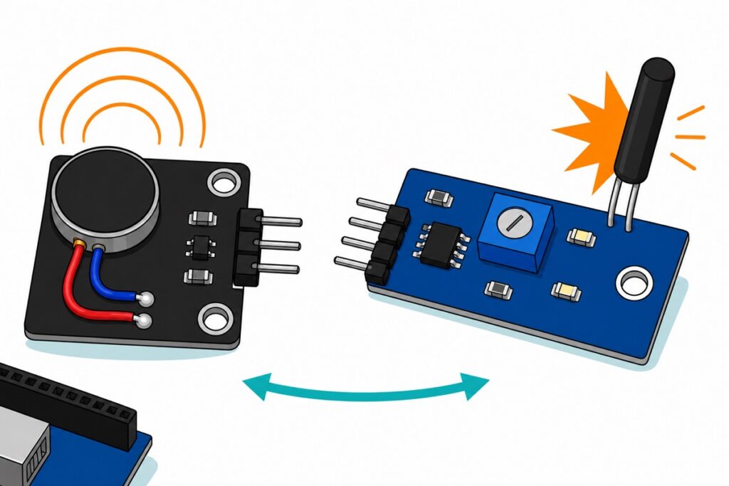
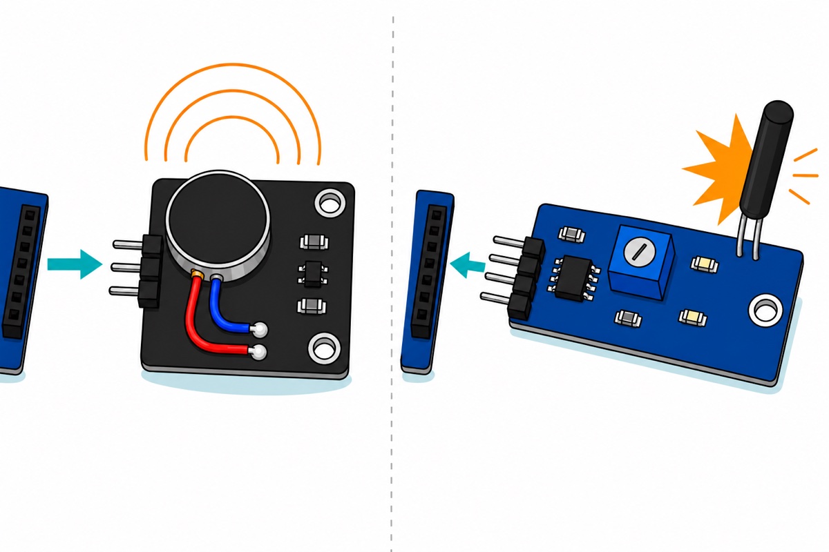
Two very different parts share the word “vibration”. A vibration motor is an output — a coin motor that makes your project shake. A vibration sensor is an input — a spring switch that notices something else shaking. Haptic buzz, silent alerts and rumble need the motor. Knock alarms, anti-theft triggers and “did it fall over” need the sensor.
Do you want to make the shaking, or notice it?
The PWM vibration motor module is an output — a mini DC vibration motor already mounted on its own little driver board. A small weight is bolted off-centre to a flat motor’s shaft, so every turn throws the weight sideways and the whole assembly jerks around its own mounting. That is all a phone’s buzz has ever been.
The SW-18010P tilt and vibration sensor module is an input, and it is the part people are usually after when they search for a vibration alarm sensor. It reports that something knocked, bumped, tipped or dropped whatever it is screwed to. It cannot shake anything, and it has no idea how hard the knock was — only that one happened.
| What you are building | Which part | Why |
|---|---|---|
| Silent alert, wearable buzz, button feedback, robot rumble | Vibration motor module | An output you drive from a pin |
| Knock alarm, anti-theft trigger, tamper detector on a project box, a drawer, a door or a parked motorcycle | Vibration sensor module | An input that fires on impact |
| “Did it fall over / get moved” watchdog | Vibration sensor module | The spring switch also responds to tilting |
| Knock detected → buzz on the wrist | Both | Input and output in one sketch — the build below |
| How hard, which axis, what angle, what frequency | GY-521 accelerometer | Neither vibration part measures anything |
Two near neighbours: a sound carried through the air is a microphone job (our clap switch guide), and a person crossing a room without touching anything is PIR motion.
Parts list — one Uno, both vibration parts, and the wires to join them
 Arduino Uno Compatible SMD UNO R3 with Type B Cable - ATMEGA328P with CH340G-Microcontroller Project
 PWM Vibration Motor DC 3V-6V Mini Vibrating Module for DIY Projects Arduino Robot
 Tilt Sensor Vibration Sensor Tilt Switch Module Alarm Trigger SW1801P For Arduino Application - VIBRATION/ TILT SENSOR
 40pcs Dupont Wire 10cm 20cm 30cm for Breadboard DIY Experiment Jumper Wire Breadboard wire - DUPONT WIRE M-F 20CM
Optional extras
 Buzzer Active Passive Buzzer 5V Electronic Sound Alarm Module Tone Piezo - Active Buzzer Module
 Electronic Component Set Beginner Electrical Learning Kit For Arduino Beginner Learning - ELECTRICAL STARTER KIT
Two additions, neither needed for the sketch below. The active buzzer module makes the knock detector audible from the next room; its silkscreen reads 低电平触发 — low-level trigger — so the code pulls its I-O pin LOW to sound it, which our active-versus-passive buzzer guide explains. The electronics learning kit is the discrete lane: transistors, diodes, resistors and an 830-hole breadboard, for driving a bare salvaged pager motor with a transistor and flyback diode you wire yourself.
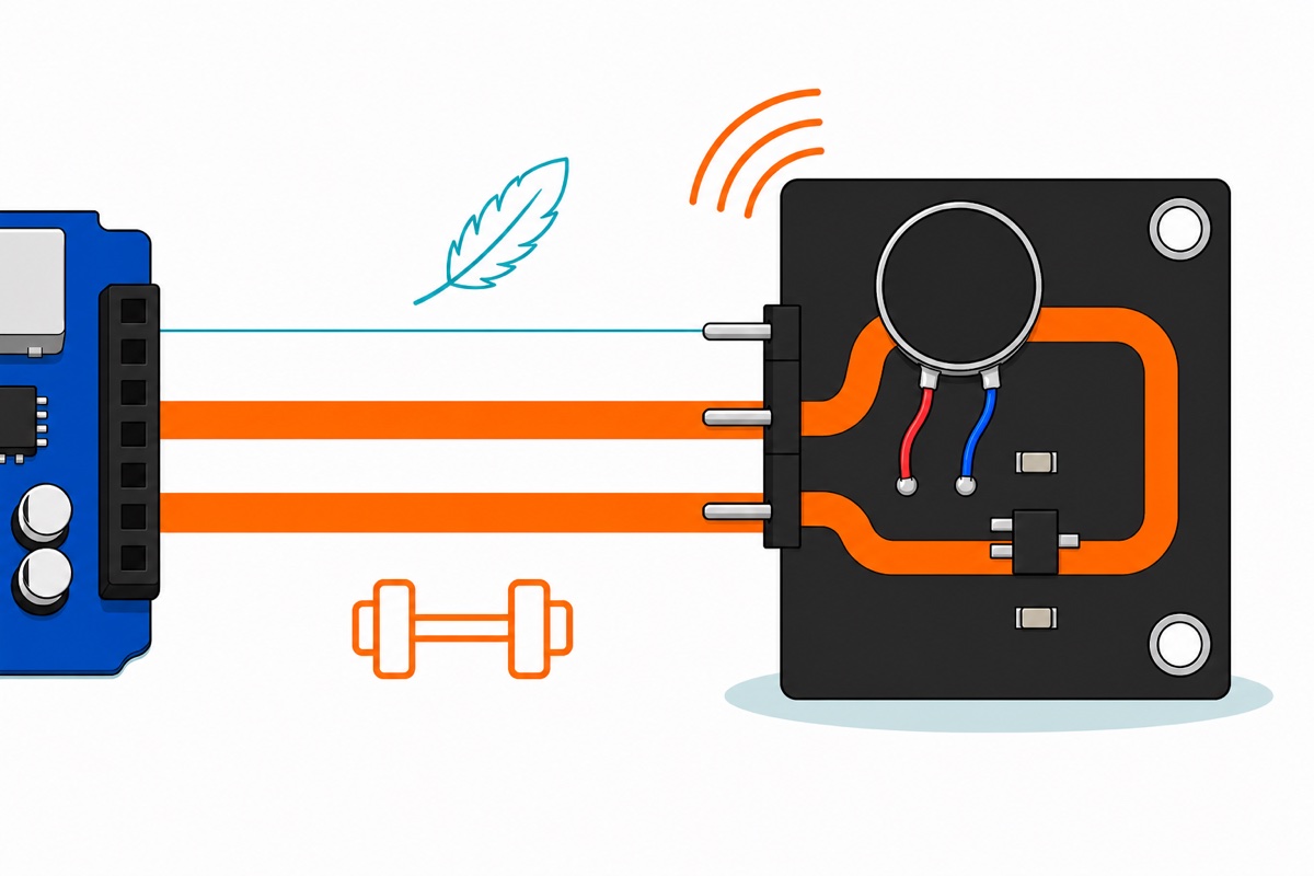
Why is a 3 V–6 V motor not a load for a bare Arduino pin?
The coin motor on the VIBRAGN module is rated 3–6 V and draws up to 90 mA. An ATmega328P I/O pin has an absolute maximum of 40.0 mA, and Arduino’s own recommended working figure is half of that, at 20 mA. So the running current alone is more than twice what the silicon survives — before you count the two things that make it worse.
The first is starting. A spinning motor generates a back-EMF that opposes its own supply and holds the current down; a stationary one generates none, so at the instant power arrives the only limit is the winding’s DC resistance. Start-up and stall therefore pull several times the running figure — and stall is just the weight jamming against a wire.
The second is stopping. The winding is an inductor, and current in an inductor cannot change instantly, so cutting the supply makes the collapsing field drive that node’s voltage upwards until something conducts. A GPIO pin is a bad volunteer for that spike, and it is the fault behind most “my board keeps resetting” motor stories.
The VIBRAGN module keeps all three off your Arduino pin, which is why it carries three right-angle pins marked IN, VCC and GND rather than two motor wires. The chain of small parts between the coin disc and the header is a driver: a transistor in a three-legged SOT-23 package with the resistors that feed and hold off its base. VCC and GND carry the motor current from the 5 V rail; IN supplies a fraction of a milliamp of base current — an instruction, not power. The layout is what does it: running current, starting surge and switch-off spike all circulate on the far side of the transistor, between the 5 V rail and ground, and none of them has a route back to the pin you wired to IN. That pin touches nothing but the base, through a resistor.
The load moves rather than vanishes, though, so budget the rail. A USB port offers 500 mA for the whole board and the Uno’s own logic takes a few tens of milliamps of that, so one 90 mA module is a comfortable fifth of the allowance. Trouble starts when a second motor, a servo or a metre of LED strip shares the same 5 V pin, because then the rail and its regulator — not the I/O pin — become the limit. Give those their own 5 V supply and tie the two grounds together, because IN is a voltage measured against ground and two supplies that never meet share no zero to measure from.
That is what makes analogWrite() on IN safe, and PWM buys more than an on/off pin does. The transistor switches fully on and fully off hundreds of times a second; the motor’s inertia and inductance average those pulses, so a duty of 200 out of 255 on a 5 V rail feels like roughly 3.9 V at the motor, less a couple of tenths across the transistor. Lower duty, gentler buzz, same part.
The floor is mechanical. A coin motor is nominally a 3 V part with a typical start voltage around 2.3 V, because held vertically it must heave its off-centre weight over the top of the shaft on the first turn. On a 5 V rail that is about 120 of 255; below it a stopped motor may sit there doing nothing, though once turning it keeps turning at lower duty. So kick it — full duty for about 30 ms, then drop to your quiet level. The sketch below starts every buzz that way, which is what lets you turn BUZZ_DUTY down to a discreet level without the motor simply refusing to start.
Seeing a coin motor actually driven from a board helps more than another paragraph does:
A bare two-wire motor salvaged from an old phone has none of that protection, so build the three parts yourself: a transistor to carry the current, a base resistor sized so the pin supplies a milliamp or two instead of the motor’s ninety, and a flyback diode reversed across the motor terminals so the collapsing field circulates its current round through the diode instead of arcing across the transistor. All three are in the electronics learning kit. The alternative is a ready-made driver such as the DRV8833 board, which adds reverse. Our MOSFET module guide works through the same low-side switching idea. Avoid the L298N here: it drops roughly two volts internally, most of a 3 V motor’s supply.
Why does the sensor fire once instead of staying HIGH?
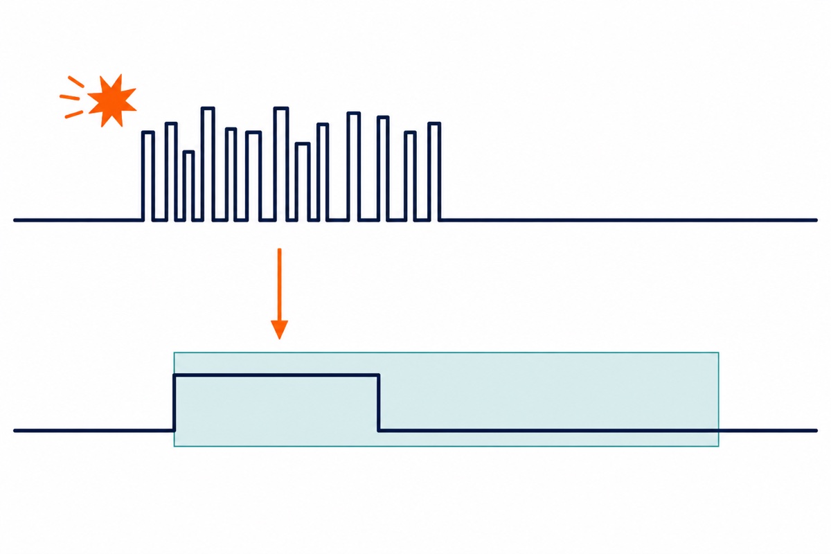
The SW-18010P inside the blue module is a spring, not a sensor in the measuring sense: a fine coil surrounds a central pin inside a sealed black tube. At rest the coil stands clear and the part is an open circuit — the manufacturer quotes over 10 MΩ open, under 30 Ω closed. A knock throws the coil sideways onto the pin, and the datasheet calls that closure a conductive time of 2 ms. Then the spring rebounds and the circuit opens again.
So the part is a switch that closes for roughly two thousandths of a second per bump, from any direction, with nothing holding it shut: a tap gives you a burst of millisecond flickers, not a level you can read at leisure. A slow tilt is caught the same way, as the coil leans onto the pin under gravity.
The LM393 comparator on the board cleans that up rather than measuring it. The switch sits in a divider with a resistor, the blue trimmer sets the comparator’s reference, and the comparator’s output is open-collector. Its output transistor can only pull DO down to ground or let go and leave the board’s pull-up resistor to lift it — it never drives HIGH itself. Which of those two is the resting state depends on which comparator input the spring switch feeds; on this module DO sits HIGH at rest, and each closure yanks it hard LOW for as long as the contact lasts, which is why the DO indicator flickers on impact instead of latching on.
The trimmer and the fourth pin are narrower than they look. The trimmer moves a threshold against a signal that only ever has two levels, so it sets the comparator’s margin rather than grading a soft tap against a hard one — wound too far it stops the board responding at all, which is the usual cause of an apparently dead module. Set it the quick way: with the board resting still, turn the screw until the DO indicator is dark and stays dark, then tap the bench — the indicator should blink once per tap. If it glows steadily at rest, or refuses to blink however hard you tap, you are past the useful span in one direction or the other, so come back a quarter turn. AO is no better. A tube that is either open or shut has nothing in between to be analogue about, so that pin only ever parks near full scale at rest and drops to the floor while the contact is made — the digital answer in slower clothing, which is why sellers of this module mark AO unusable. Leave it unconnected.
Which way round DO rests is worth building into the code rather than into your assumptions, because the same spring switch turns up on boards wired both ways round. The sketch below settles it for itself: it reads the pin’s resting level once at start-up and treats any departure from that level as a knock, so it behaves correctly either way with no edit. The same class of module, exercised on a bench:
How do you make one knock count as one event?
The vibration motor module and the SW-18010P sensor module both present male pins, and the Arduino Uno has female headers, so 20 cm male-to-female jumpers finish the whole build with no breadboard and no soldering.
| Module pin | Arduino Uno pin | Note |
|---|---|---|
| Motor VCC | 5V | Motor current comes from here, not from D9 |
| Motor GND | GND | Shared ground with everything else |
| Motor IN | D9 | Must be a PWM pin (3, 5, 6, 9, 10, 11) |
| Sensor VCC | 5V | Module works on 3.3–5 V |
| Sensor GND | GND | |
| Sensor DO | D2 | Digital output — the pin the sketch watches, and the Uno’s INT0 if you later want an interrupt |
| Sensor AO | — | Leave unconnected |
Then fix both modules down before you judge either. A coin motor held in the air spins its weight against nothing you can feel; screwed through the module’s two plated mounting holes to the lid of a box, it buzzes the whole box. The sensor is that rule inverted — it only receives what its own board receives, so a module taped to foam or dangling on its jumpers misses knocks that a screwed-down one catches. Mount the two apart where you can, because the motor shakes the sensor as surely as your knuckle does, and the sketch below takes that seriously.
Now the software problem. One knuckle rap makes the spring rattle, so the pin sees a scatter of 2 ms pulses over tens of milliseconds and a plain counter reports a dozen knocks for one. Treat an event as a transition followed by a deaf period: note the time on the first reading that differs from rest, then ignore the pin until a lockout expires.
Bracket that lockout. It must outlast the rattle from one impact and stay shorter than the gap between two raps you want counted separately, and 250 ms sits comfortably between the two. It is the reasoning behind button debouncing in our push button guide, with a longer window because a spring rings longer than a dome contact.
One extra trap belongs to this particular pairing. The motor you just started is shaking the same bench as the sensor, so a detector that re-arms while the buzz is still running hears itself, retriggers, and buzzes forever — lengthen BUZZ_MS past LOCKOUT_MS in a naive sketch and that is exactly what happens. Two lines close it: refuse to look at the pin at all while the motor is running, and restart the lockout clock at the moment the motor stops rather than at the moment the knock arrived. Recovery time then reads honestly as buzz plus lockout — 150 ms and 250 ms here, so about two deliberate knocks a second.
Two habits carry the rest. Measure the resting level instead of assuming HIGH, so the sketch survives a board wired the opposite way round; and time the buzz with millis() rather than delay(), because a delay is deaf and every knock inside it is lost. That is also why DO sits on D2: it is the Uno’s INT0 pin, so when your loop eventually grows heavy enough to miss a 2 ms pulse you can move detection into an interrupt without rewiring anything.
/*
  Knock in, buzz out - MakerHub
  SW-18010P sensor module: VCC->5V, GND->GND, DO->D2  (AO left unconnected)
  PWM vibration motor module: VCC->5V, GND->GND, IN->D9  (D9 must be a PWM pin)
*/

const uint8_t SENSOR_PIN = 2;   // DO of the sensor module
const uint8_t MOTOR_PIN  = 9;   // IN of the motor module

const uint8_t  KICK_DUTY  = 255;  // full duty for the first instant, to break the weight loose
const uint16_t KICK_MS    = 30;   // how long that kick lasts
const uint8_t  BUZZ_DUTY  = 200;  // 0-255 after the kick. 200 averages about 3.9 V on a 5 V rail
const uint16_t BUZZ_MS    = 150;  // total length of one alert buzz, kick included
const uint16_t LOCKOUT_MS = 250;  // one knock = one event: ignore pulses for this long

int      idleLevel;               // whatever DO reads when nothing is happening
uint32_t lastKnockMs;
uint32_t buzzStartedMs = 0;
bool     buzzing       = false;
uint32_t knockCount    = 0;

void setup() {
  Serial.begin(9600);
  pinMode(SENSOR_PIN, INPUT);
  pinMode(MOTOR_PIN, OUTPUT);
  analogWrite(MOTOR_PIN, 0);

  // Measure the resting level instead of assuming it. Keep the board still here.
  delay(200);
  idleLevel = digitalRead(SENSOR_PIN);
  Serial.print(F("DO rests at: "));
  Serial.println(idleLevel == HIGH ? F("HIGH") : F("LOW"));

  // Arm straight away; unsigned subtraction wraps correctly.
  lastKnockMs = millis() - LOCKOUT_MS;
}

void loop() {
  uint32_t now = millis();

  // Input: turn a burst of millisecond contact pulses into one event - and never
  // while our own motor is running, or the alarm would hear itself.
  if (!buzzing && digitalRead(SENSOR_PIN) != idleLevel && (now - lastKnockMs) >= LOCKOUT_MS) {
    lastKnockMs = now;
    knockCount++;
    Serial.print(F("Knock #"));
    Serial.println(knockCount);

    analogWrite(MOTOR_PIN, KICK_DUTY);
    buzzStartedMs = now;
    buzzing = true;
  }

  // Output: kick, settle, stop - all on the clock, so nothing here blocks the loop.
  if (buzzing) {
    if ((now - buzzStartedMs) >= BUZZ_MS) {
      analogWrite(MOTOR_PIN, 0);
      buzzing = false;
      // Our own motor has been shaking the sensor. Start the deaf period again
      // here, measured from the moment the shaking stopped.
      lastKnockMs = now;
    } else if ((now - buzzStartedMs) >= KICK_MS) {
      analogWrite(MOTOR_PIN, BUZZ_DUTY);
    }
  }
}
Open the Serial Monitor at 9600 baud and tap the desk near the sensor: one numbered line and one short buzz per tap. If a tap still counts twice, raise LOCKOUT_MS; if two knocks merge into one, lower it. To make the alert audible rather than felt, put an active buzzer module on another pin and drive it LOW, as our active versus passive buzzer guide explains.
What can neither of these parts tell you?
Neither the vibration motor module nor the SW-18010P sensor measures anything. The motor has no feedback at all — you set a duty and hope. The SW-18010P answers yes or no, and even that is not guaranteed: the manufacturer quotes a 98% conduction rate over a hundred switch actions, so roughly one gentle bump in fifty is missed. Mounting beats code here, because a board taped to a soft surface never receives the jolt.
If your project needs a number — how hard, along which axis, at what angle or what frequency — the answer is an accelerometer. The GY-521 breakout carrying an MPU-6050 returns three axes of acceleration and three of rotation over I²C, and our GY-521 tilt tutorial gets you to live readings; an ADXL345-class part is the other common answer.
Common mistakes we see
Ordering by the shared word. “Vibration module” is not a part; it is two parts with opposite jobs whose search results look nearly identical. Decide whether your sketch is telling or asking, then order.
Wiring a salvaged pager motor straight to a pin. The two-wire motor pulled from an old phone looks like the disc on our module, but arrives with none of the electronics that make that module safe. Give it a transistor, a base resistor and a flyback diode, or a driver board.
Polling for a level instead of catching a pulse. The pattern that fails is if (digitalRead(DO) == LOW) { alarm(); } delay(100); — a 2 ms contact against a 100 ms blind spell, so most knocks land while the sketch is asleep. Delete the delay without adding a lockout and the opposite happens: one rattle counts a dozen times. Watch for a transition, then lock out.
FAQ
What is the difference between a vibration motor and a vibration sensor?
A vibration motor is an output: a coin motor with an off-centre weight that makes your project shake, for haptic alerts. A vibration sensor is an input: a spring switch that reports when something else shakes it, for knock alarms and tamper detection.
Can I connect a vibration motor directly to an Arduino pin?
Not a bare motor: it draws up to 90 mA where an ATmega328P pin’s absolute maximum is 40 mA, plus a larger start-up surge and an inductive spike at switch-off. The PWM vibration motor module is safe because its onboard transistor carries that current from the 5 V rail, leaving IN to carry only a signal.
Why does my vibration sensor trigger many times for one knock?
Because the SW-18010P is a spring that closes for about 2 ms per contact and rattles several times per impact. Count transitions rather than levels, and ignore the pin for a lockout period of roughly 250 ms after each accepted knock.
Is the vibration sensor’s DO pin HIGH or LOW when idle?
On this module DO rests HIGH and is pulled LOW for as long as the spring is in contact. The LM393’s open-collector output only ever pulls down against the board’s pull-up resistor, so which of the two states is the resting one comes down to how the comparator’s inputs are wired, and boards in this family exist both ways round. Read the pin’s resting level at start-up and compare against that instead of hard-coding HIGH.
Can a vibration sensor measure how strong the vibration is?
No. It is a bump detector with a yes/no output, and its analogue pin is not a magnitude reading. For force, axis, angle or frequency you need an accelerometer such as the MPU-6050 on a GY-521 board.
Last updated August 2026. Stuck? Chat with us on WhatsApp.
