

Tutorials
Arduino Clap Switch Code with the KY-037 Sound Sensor
Aug
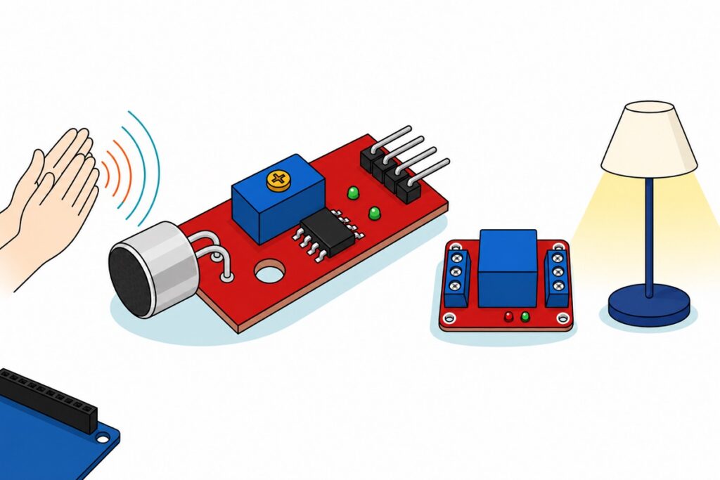
A clap switch that keeps working reads the KY-037’s analog pin, not its digital one: sample A0 as fast as the ADC allows, measure how far the signal swings inside a 20 ms window, and count two swings 120–800 ms apart as one toggle. The trimmer-and-D0 build every guide shows works on the bench and drifts by evening; this one holds.
What do you need to build an Arduino clap switch?
The KY-037 sound sensor is a small red board with a silver electret capsule on two bent legs, a blue trimmer, an LM393 and four straight male pins. Those pins set the wiring: it seats straight into a breadboard, and male-to-male jumpers reach the Uno‘s female headers.
Parts list — KY-037 clap switch with a 5 V relay on an Arduino Uno
 Analog Digital Sound Detector Mic Microphone 4 Pin KY 037 KY-037 For Arduino IOT Application
 Arduino Uno Compatible SMD UNO R3 with Type B Cable - ATMEGA328P with CH340G-Microcontroller Project
 Relay Module 3.3V 5V 12V 1/2/4/8 Ways Optocoupler Trigger Relay Module 1 2 4 8 Channel Relay Module - 5V RELAY MODULE(1WAY)
 MB102 Breadboard 170 400 830 Holes Breadboard Donut Board Arduino Prototype Multi Color - BREADBOARD (400 HOLES)
 40pcs Dupont Wire 10cm 20cm 30cm for Breadboard DIY Experiment Jumper Wire Breadboard wire - DUPONT WIRE M-M 20CM
Optional — USB lead and a panel indicator LED
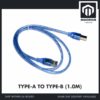 Data Cable Type-A Type-C MicroUSB Type-B 0.5m 1m 30cm 0.3m 100cm Data Transfer Upload Code - TYPE-A TO TYPE-B (1.0M)
 Round Head LED 3mm / 5mm / 8mm - Red/Yellow/Blue/Green/White - 5mm LED (GREEN)
 Electronic Component Set Beginner Electrical Learning Kit For Arduino Beginner Learning - ELECTRICAL STARTER KIT
The Uno's socket takes a full-size USB-B (printer-style) plug — add one if that square connector is not already in your drawer. The first stage of this build blinks the Uno's own pin-13 LED and needs nothing extra; the 5 mm green LED is for a panel indicator, and it needs a series resistor in line with it — 220 Ω is the usual choice, and the starter kit's resistor strips are where to find one.
The relay module is the 5 V version because its Songle SRD-05VDC-SL-C coil runs off the Uno’s own rail; the 12 V module is the same red board with a 12 V coil and belongs in a system that already has 12 V. Male-to-female jumpers skip the breadboard; the FT232 Uno suits a PC that fights CH340 drivers.
How does the KY-037 turn a clap into a signal?
The KY-037’s electret capsule is biased through a resistor from the + pin, and sound is a pressure oscillation, so that node carries an alternating signal on a steady DC level. A clap swings it above and below that idle voltage for a few milliseconds, then reflections ring it down over tens of milliseconds more. A0 is that node.
The KY-037’s LM393 compares that node against a reference set by the blue trimmer — marked 104, ten followed by four zeros, so 100 kΩ — and drives D0 from the result. That output is open-collector: a transistor that can pull the pin to ground and nothing that can push it up, so the board fits its own pull-up and an indicator LED. D0 answers one question fixed in hardware; A0 is the whole signal.
| Pin (silkscreen order) | Connect to | What it carries |
|---|---|---|
A0 |
Uno A0 |
The microphone node itself — an AC swing on a DC bias |
G |
− rail (GND) |
Ground. Note it sits second, not at the end |
+ |
+ rail (5 V) |
Supply for the mic bias and the LM393 |
D0 |
Leave unconnected | Comparator output. This sketch does not use it |
How do you wire the KY-037 and relay module to an Uno?
The Uno has a single 5 V socket and two modules need it, so feed the breadboard rails from that socket first and take both supplies from the rails. Seat the KY-037 against its silkscreen: ground sits second in that row, so a module one position out puts 5 V into the analog input. The relay has a three-way screw terminal at each edge — NO/COM/NC for contacts, IN/DC−/DC+ for control — so clamp a jumper pin under each screw.
| From | To | Why |
|---|---|---|
Uno 5V, GND |
+ and − rails |
Two male-to-male jumpers. One socket becomes a rail both modules can share |
KY-037 +, G |
+ and − rails |
Mic bias and comparator supply |
KY-037 A0 |
Uno A0 |
The signal the sketch measures |
Relay DC+, DC− |
+ and − rails |
Powers the board and the coil — about 71 mA when pulled in |
Relay IN |
Uno D8 |
Drives the optocoupler’s LED only, a few milliamps |
| Lamp | Relay COM and NO |
Off whenever the relay is off or the board is unpowered |
| Optional LED | Uno D13 → 220 Ω → LED long leg, short leg to − rail |
Panel indicator in parallel with the onboard LED the sketch already drives. The resistor is not optional |
Why does the trimmer-and-D0 clap switch never stay tuned?
The KY-037’s trimmer sets exactly one number — the voltage the microphone node must cross for D0 to flip — and that single fixed threshold causes three problems. Our LDR night light makes the same argument about light.
The threshold is fixed and the room is not. A fan, rain on a metal roof or the aircon compressor cutting in all lift the ambient level by tens of millivolts, so a setting tuned at 11 pm either misses claps at lunchtime or fires on passing traffic. The trimmer knows nothing about the room it sits in.
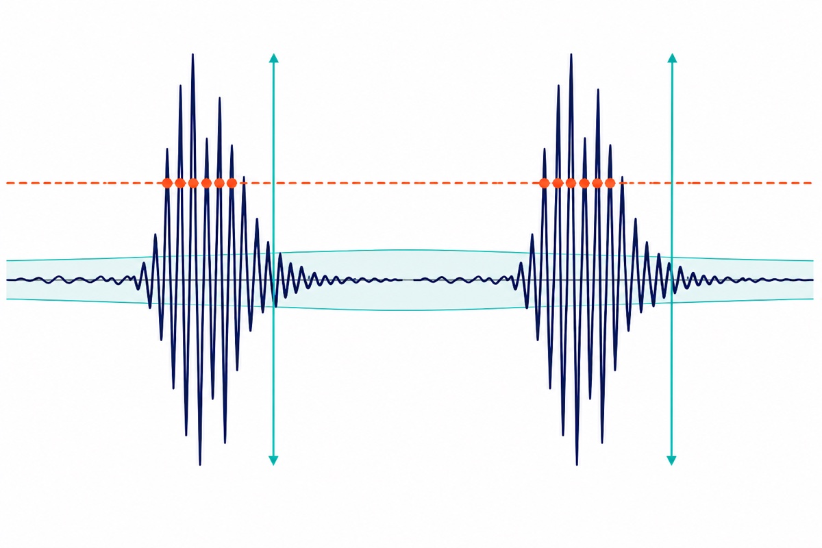
One clap is many edges. The waveform crosses the threshold on the way up, again on the way down, and again on every reflection still loud enough, so one clap produces a ragged burst. Code that toggles on each edge toggles several times — which is why the naive clap switch flashes instead of switching.
Near the set point it chatters. Sound hovering at the threshold crosses it repeatedly — and the trimmer is a multi-turn type, so the screw takes many turns to cross its range and slips with a click at each end. “Turn it until it works” often ends with the screw at a stop:
D0 is not useless, but it will not drive this relay the obvious way round. An LM393 sinks strongly and sources only through its pull-up — a fraction of a milliamp where the optocoupler’s LED wants a few — so the jumper has to go to L, where the relay pulls in whenever D0 is LOW. On the KY-037 that LOW is the resting state and the clap is the HIGH — the board’s own D0 indicator LED flicks state with it, so you can watch the pin answer a clap before you wire anything to it. So the lamp burns through the quiet and drops out while the noise lasts; move it to NC instead of NO and noise switches the lamp on again, at the cost of the fail-safe, because an NC lamp is also lit whenever the board loses power. Either way it is momentary. A toggle needs memory, and memory needs code.
How does the clap switch code detect a clap on A0?
Measure the swing, not the level. The sketch samples the KY-037’s A0 pin flat out for 20 ms and keeps only the highest and lowest reading; their difference is the peak-to-peak swing. Twenty milliseconds is long enough that the loudest few milliseconds of a clap always land inside one window, and short enough that the two-clap timing that follows still has fine grain. Subtracting one sample from another cancels the DC bias, so the idle level never has to be known, and it makes no difference whether the signal moves up or down first.
The Uno’s ADC runs from a 125 kHz clock — 16 MHz over the Arduino core’s default prescaler of 128 — and each conversion takes 13 cycles, so analogRead() returns about 9,600 samples a second, roughly 190 per window. Far too slow to reconstruct audio, and it need not be: content above half the sample rate folds back down rather than vanishing, and still lands as large samples. We measure how hard the signal moves, not what it says.
The threshold is then the room’s own noise floor plus a margin. The sketch averages the swing of quiet windows, nudging it 3% of the way each window — 20 ms a step, so about thirty windows, two-thirds of a second, to follow a change in the room — and skips any window containing a clap, so a clap can never raise the bar it just cleared. A margin of 80 counts is 80 × 4.9 mV ≈ 0.39 V of extra swing — well clear of what a quiet room wanders, and a sensible opening number for a clap at arm’s length. A0 is the microphone’s own node with no amplifier behind it, so that swing shrinks quickly as you step back: the Serial line prints what your claps really measure, and the margin follows that number.
How do two claps become exactly one toggle?
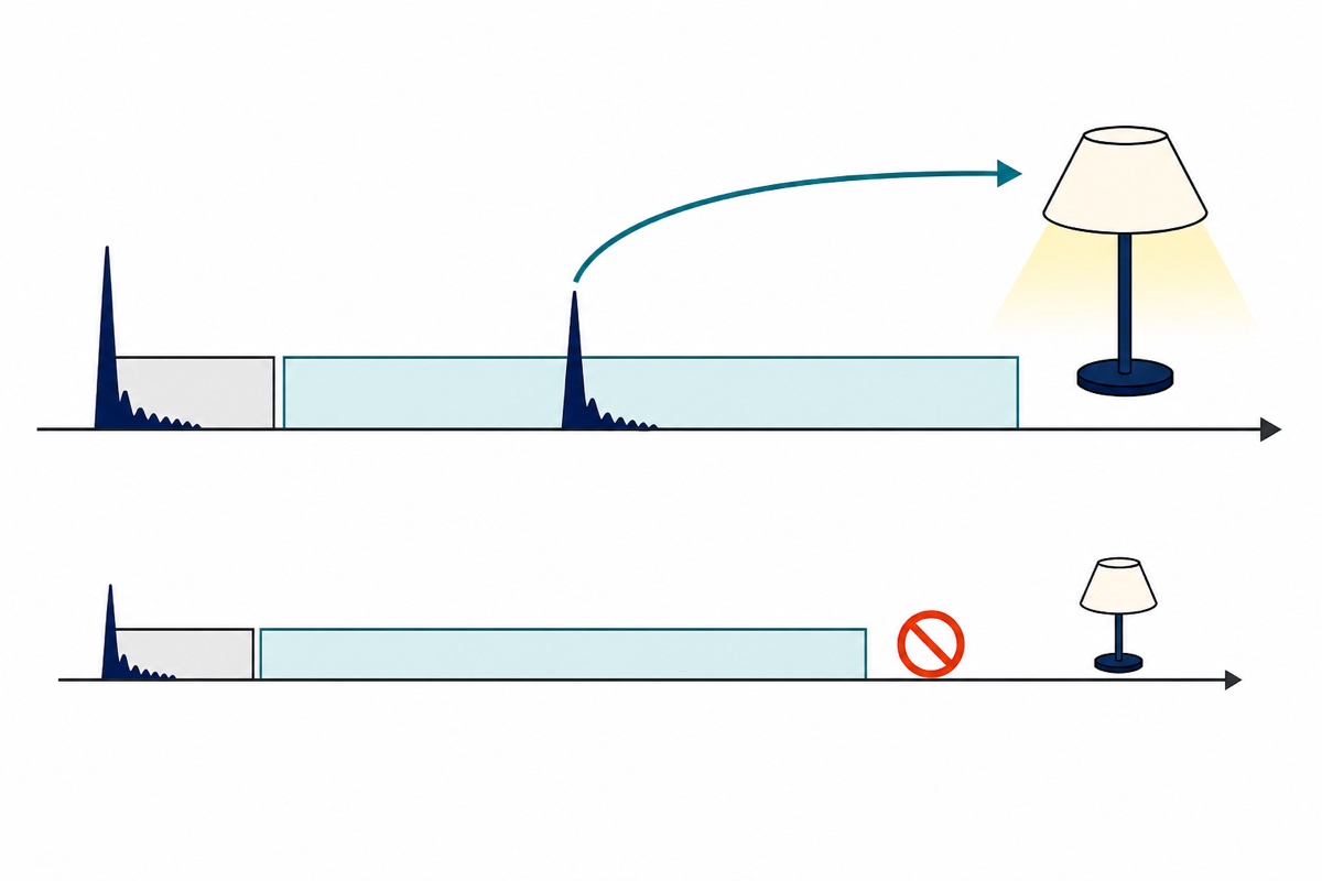
The first accepted swing starts a clock, and for 120 ms the sketch is deliberately deaf: a clap’s direct sound lasts a few milliseconds but its reflections hold the level up far longer, and nobody claps twice inside a tenth of a second — so anything in that stretch is the same clap again. From 120 ms to 800 ms a second swing toggles the lamp. Past 800 ms the machine gives up, so a door slam alone changes nothing, and neither does one loud laugh.
Both figures are constants, not physics: widen GAP_MAX if your second clap arrives late, lengthen REFRACTORY if the Serial output counts one clap twice in a hard-walled tiled room.
/*
  Clap switch - KY-037 sound sensor -> Arduino Uno -> 5 V relay module.
  No library needed.

  KY-037  +  -> breadboard + rail (5 V)      G  -> breadboard - rail (GND)
  KY-037  A0 -> Uno A0                       D0 -> not used by this sketch
  Relay   DC+ -> + rail    DC- -> - rail     IN -> Uno D8
  Relay jumper stays on H (high-level trigger) as it ships.

  The sketch measures how far the microphone signal SWINGS in a short window,
  not what level it sits at, so the DC bias and the trimmer are both irrelevant.
  Two swings inside the timing window toggle the lamp.
*/

const uint8_t PIN_MIC   = A0;
const uint8_t PIN_RELAY = 8;
const uint8_t PIN_LED   = 13;   // the Uno's own LED - stage one needs no relay

const uint16_t WINDOW_MS   = 20;    // length of one measurement window
const int      CLAP_MARGIN = 80;    // ADC counts a clap must beat the room by
const uint16_t REFRACTORY  = 120;   // ms of deafness after a clap (its own echo)
const uint16_t GAP_MAX     = 800;   // ms: the latest a second clap may arrive

// Relay jumper on H (as shipped) = HIGH energises. Set false if you move it to L.
const bool RELAY_ACTIVE_HIGH = true;

float    ambient     = 0;   // running noise floor, in counts of swing per window
bool     lampOn      = false;
uint8_t  state       = 0;   // 0 = waiting for clap one, 1 = waiting for clap two
uint32_t lastClapAt  = 0;
uint32_t firstClapAt = 0;

// Sample as fast as analogRead() allows for WINDOW_MS and return the
// peak-to-peak spread. Subtracting min from max cancels the DC bias.
int measureWindow() {
  uint16_t lo = 1023, hi = 0;
  uint32_t start = millis();
  while (millis() - start < WINDOW_MS) {
    uint16_t s = analogRead(PIN_MIC);
    if (s < lo) lo = s;
    if (s > hi) hi = s;
  }
  return (int)(hi - lo);
}

void setLamp(bool on) {
  lampOn = on;
  digitalWrite(PIN_LED, on ? HIGH : LOW);
  digitalWrite(PIN_RELAY, (on == RELAY_ACTIVE_HIGH) ? HIGH : LOW);
}

void setup() {
  pinMode(PIN_RELAY, OUTPUT);
  pinMode(PIN_LED, OUTPUT);
  setLamp(false);                 // drive the relay off before anything else
  Serial.begin(115200);

  // Learn the room: 50 windows is about one second. Keep quiet during it.
  long sum = 0;
  for (uint8_t i = 0; i < 50; i++) sum += measureWindow();
  ambient = sum / 50.0;

  Serial.print(F("noise floor "));
  Serial.print(ambient, 1);
  Serial.print(F(" counts, clap needs "));
  Serial.println(ambient + CLAP_MARGIN, 1);
}

void loop() {
  int      amp  = measureWindow();
  uint32_t now  = millis();
  bool     loud = amp > (int)(ambient + CLAP_MARGIN);

  // Only quiet windows move the noise floor: 3% per 20 ms window follows the
  // room over roughly two-thirds of a second, and a 20 ms clap never budges it.
  if (!loud) ambient += 0.03f * (amp - ambient);

  bool clap = loud && (now - lastClapAt >= REFRACTORY);
  if (clap) {
    lastClapAt = now;
    Serial.print(F("clap, swing "));
    Serial.println(amp);
  }

  if (state == 0) {
    if (clap) { firstClapAt = now; state = 1; }
  } else {
    if (clap) {
      setLamp(!lampOn);
      Serial.println(lampOn ? F("lamp ON") : F("lamp OFF"));
      state = 0;
    } else if (now - firstClapAt > GAP_MAX) {
      state = 0;                  // one clap alone changes nothing
    }
  }
}
On an Uno this compiles to 4,418 bytes of flash — 13% of the 32 KB — and 214 bytes of RAM. Run it with the relay unwired first: the same sketch drives the Uno’s own pin-13 LED, so you can get the claps landing reliably before anything clicks. The Serial Monitor at 115200 prints the measured noise floor and every clap’s swing, so a missed clap tells you how far short it fell.
How does the relay stage switch the lamp?
The relay module’s SRD-05VDC-SL-C coil is 70 Ω, so pulling it in draws 5 V ÷ 70 Ω ≈ 71 mA. With the Uno’s own 45 mA or so and the sensor’s few, the build sits near 120 mA — inside the 500 mA the Uno’s USB polyfuse allows, which is why nothing here needs a second supply. The Uno pin never carries that 71 mA: IN drives only the optocoupler’s LED at a few milliamps, and DC+ feeds the coil. Both sides of that optocoupler share DC− here, so it buffers rather than isolates: the isolation that matters is inside the relay, whose contacts are mechanically separate metal from the coil.
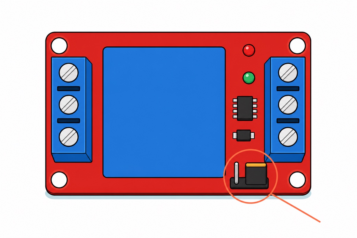
The black jumper block ships with its cap on H, high-level trigger — the board prints L beside one end of that little header and H beside the other, so one glance confirms it before you power up — and that default is the right one: an Arduino’s pins are high-impedance inputs from power-on until setup() runs, so a floating or LOW IN leaves the lamp off through the whole boot. It is also the commonest cause of “my relay works backwards”, since sketches copied from low-trigger boards write LOW to switch on. Move the cap to L and you must set RELAY_ACTIVE_HIGH to false.
Wire the lamp through COM and NO so it is dark whenever the relay is off or unpowered. Those two screws are a mechanical switch, not an output: the lamp keeps its own supply — cut the positive lead of that supply and clamp one end into COM, the other into NO, so nothing from the Uno’s rail ever reaches the lamp. The case prints what the contacts may carry: 10 A at 250 V AC, 10 A at 30 V DC, resistive. Everything here stays low-voltage DC — a 12 V LED strip or small DC lamp on its own supply. A 240 V lamp brings its own rules on enclosures, clearances, cable rating and terminals you can touch: read our relay module safety guide first. A clap is voice control with a vocabulary of one, so the voice control module is the natural step up from here; if what you want is a light that follows movement instead of sound, the PIR sensor is the better sensor.
Common mistakes we see from real customers
Expecting it to work through loud music. Only quiet windows move the noise floor — that is exactly what stops a clap raising the bar it just cleared — so a sustained loud sound is a bar the floor can never climb to, and the sketch reads it as clap after clap after clap. Raise CLAP_MARGIN, move the sensor away from the speaker, or accept that a clap switch listens for transients above a quiet-ish room rather than inside a noisy one.
Toggling on each edge of D0. A clap that produces six crossings toggles six times, so where the lamp ends up is a coin flip. Counting edges is not the fix; ignoring everything for 120 ms after the first one is.
Turning the trimmer to fix an analog build. The trimmer sets the LM393’s reference, and that reference only reaches D0 — it cannot touch the A0 signal this sketch reads.
FAQ
Why does my clap switch turn on and off by itself?
Something is clearing the threshold twice inside the window. Raise CLAP_MARGIN, and keep the sensor away from the relay’s click.
Can I use the KY-037’s D0 pin instead of A0?
For a momentary sound-triggered relay, yes, once you allow for D0 resting LOW and going HIGH on the sound. For a two-clap toggle, no — one fixed threshold, several edges per clap.
Why does my relay switch the wrong way round?
The cap ships on H, so HIGH energises the coil while low-trigger sketches write LOW. Move the cap, or set RELAY_ACTIVE_HIGH to false.
Can the Arduino’s 5 V pin power the relay module?
Yes, for the 5 V module: 71 mA of coil against a 500 mA USB budget. A 12 V coil will not pull in on 5 V.
How far away can I clap?
As far as the swing still beats the noise floor by CLAP_MARGIN. Sound pressure falls with distance while the floor does not — lower the margin or move the sensor.
Last updated August 2026. Stuck? Chat with us on WhatsApp.

Pingback: Vibration Motor vs Vibration Sensor for Arduino