

Tutorials
DRV8833 vs L298N: Which Motor Driver Should You Buy?
Sep
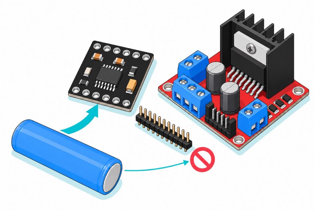
The DRV8833 is a dual H-bridge motor driver — two DC brush motors, or one bipolar stepper, from a board 1.8 x 2.1 cm — and it beats the L298N whenever the motors run off a battery. It works from 2.7 V and loses about 0.36 V inside its own bridge, so a single 18650 at 3.7 V still puts roughly 3.4 V across the motor. An L298N wants about 5 V before it starts and then eats 1.8 V to 3.2 V of whatever you feed it. On a wall adapter or 12 V motors, the L298N is the better buy.
What is the DRV8833 module, and what is on the board?
The DRV8833 module is a Texas Instruments DRV8833 chip on a black square of PCB 1.8 x 2.1 cm across. Inside that chip are two complete H-bridges, so one board runs two DC brush motors independently, or one bipolar stepper with a coil on each bridge.
Two printed names on the back are truncated. EEP is nSLEEP, the enable pin, and ULT is nFAULT, the fault flag. The rest read VCC, GND, IN1 to IN4 and OUT1 to OUT4. Notice what is missing: there is no separate logic supply pin. The chip runs its own control circuitry from the motor supply, which is exactly why the 2.7 V floor is a real floor and not a marketing number.
The two drivers, plus a rig to compare them on
 DRV8833 Dual Motor Driver 2 DC Motors 1.5A Arduino Smart Car Project
 L298N Motor Driver Module Arduino Compatible Dual H Bridge Dual DC Motor Control Arduino Robotic Car
 Arduino Uno Compatible SMD UNO R3 with Type B Cable - ATMEGA328P with CH340G-Microcontroller Project
 200RPM TT MOTOR With 68mm Wheel 3V 5V 6V 9V Motor Plastic Gear Motor For Arduino Smart Car - TT MOTOR
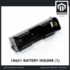 18650 Battery Holder 1/2/3/4 Slot 3.7V Battery Cell Housing Battery Case Battery Casing - 18650 BATTERY HOLDER (1)
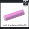 3.7V 18650 Battery Rechargeable Li-Ion Battery 1200mAh 2200mAh 3200mAh Flat Top - 18650 Li-Ion Battery (2200mAh)
 40pcs Dupont Wire 10cm 20cm 30cm for Breadboard DIY Experiment Jumper Wire Breadboard wire - DUPONT WIRE M-F 20CM
Parts list
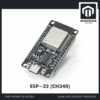 NodeMCU ESP32 Wi-Fi + Bluetooth Development Board CH340/CP2012 - For IOT Project - ESP-32 (CH340)
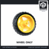 200RPM TT MOTOR With 68mm Wheel 3V 5V 6V 9V Motor Plastic Gear Motor For Arduino Smart Car - WHEEL (FOR TT MOTOR)
 MB102 Breadboard 170 400 830 Holes Breadboard Donut Board Arduino Prototype Multi Color - BREADBOARD (830 HOLES)
 40pcs Dupont Wire 10cm 20cm 30cm for Breadboard DIY Experiment Jumper Wire Breadboard wire - DUPONT WIRE M-M 20CM
 18650 Battery Holder 1/2/3/4 Slot 3.7V Battery Cell Housing Battery Case Battery Casing - 18650 BATTERY HOLDER (2)
Three separate lanes, not one basket. Building the 2WD robot: add two 68 mm wheels, which push onto the TT motors' white cross shafts. Running the driver from an ESP32 instead of an Uno: take the ESP32 dev board and skip the Uno. Prefer to work on a breadboard: once the header pins are soldered on, the DRV8833 straddles a breadboard channel like a chip, and male-to-male jumpers reach it from there. The 2-slot 18650 holder is for the 7.4 V two-cell pack described in the voltage section.
Why does one 18650 run a robot on a DRV8833 and stall it on an L298N?
The DRV8833’s bridges are made of N-channel MOSFETs, and a MOSFET that is switched on behaves like a small resistor. TI’s datasheet puts the high-side FET at 200 mΩ and the low-side at 160 mΩ at 5 V and room temperature, and current flows through one of each on the way to the motor and back. That is 360 mΩ in the path, so at 1 A the driver keeps 0.36 V and hands the motor the rest. Both figures climb as the supply drops or the chip warms — 250 mΩ and 200 mΩ at the bottom of the range — so budget nearer 0.45 V at 1 A on a half-flat cell. What matters is that the loss follows the current: ask for half an amp and you lose half as much.
The L298 inside the red board is an older design built from bipolar transistors, and a bipolar transistor in saturation drops a roughly fixed voltage however little current you ask of it. ST’s datasheet gives the total drop across both halves of one bridge at 1 A as 1.8 V at best and 3.2 V at worst; add its typical source and sink saturation figures, 1.35 V and 1.2 V, and a normal part sits at about 2.55 V.
The L298’s logic side also wants its own 4.5 V to 7 V supply, and the red module covers that with a small onboard 5 V regulator, switched in by the jumper beside the power terminals, which feeds the logic from the motor supply as long as that supply stays under 12 V. But a linear regulator only steps a voltage down, with a couple of volts of headroom to do it, so it wants roughly 7 V at the motor terminals before it can make a clean 5 V — hand that board a single 3.7 V cell and its logic supply fails before the motors are even part of the argument.
Now put a single 18650 cell in a holder and do the arithmetic for a pair of TT gearmotors, which are rated 3 V to 6 V.
| Supply | Lost in the bridge | Left for the motor | Result |
|---|---|---|---|
| 1 x 18650, 3.7 V, into a DRV8833 | ~0.2 V at half an amp | ~3.5 V | Turns — inside the motor’s 3-6 V range |
| 1 x 18650, 3.7 V, into an L298N | 1.8-3.2 V | 0.5-1.9 V | Below the motor’s range; will not start |
| 2 x 18650 in series, 7.4-8.4 V, DRV8833 | ~0.2 V | 7.2-8.2 V | Too much — limit the PWM duty |
| 9 V or 12 V adapter into an L298N | 1.8-3.2 V | 6-10 V | Fine — this is the L298N’s home ground |
A fixed 2.5 V loss is nothing out of 12 V and fatal out of 3.7 V. On a two-cell pack, 8.4 V fully charged is still under the DRV8833’s 10.8 V ceiling but well over what a 6 V motor wants, so cap the PWM at about 185 of 255 — 6 V divided by 8.2 V is roughly 73 percent duty. Charge a two-cell pack only with a two-cell charger: see our guide to 18650 packs, BMS boards and charging, or TP4056 charging for the single cell.
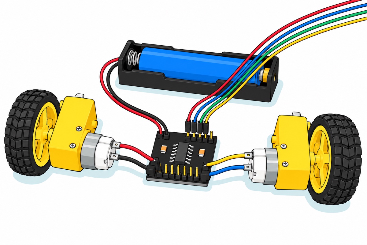
How much current does the DRV8833 really give, and why does the L298N need that heatsink?
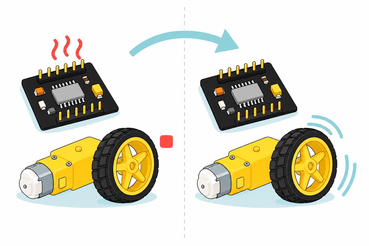
The DRV8833 is rated at 1.5 A continuous per channel and 2 A peak. That figure is a heat limit, not a fuse, and the heat is easy to work out: the driver’s own resistance turns current into power at I squared times R. At 1 A that is 1 A x 1 A x 0.36 Ω = 0.36 W spread over a chip soldered flat to the board’s copper — a warm chip, nothing more. Two TT motors on a small robot draw a few hundred milliamps each, well below that ceiling.
Run the same sum on the L298N and the heatsink stops looking like decoration. Its loss is voltage times current rather than I squared R, so at 1 A per channel across two channels it is 2.55 V x 1 A x 2 = 5.1 W. A bare L298 package in still air sheds heat at about 35 °C per watt, which would be a 178 °C rise against a 130 °C junction limit. Bolt it to that finned block and the heat has somewhere to go, which is why the board is built that way, and why the L298N’s headline 2 A per channel is honest only with the heatsink attached and the fins in open air.
How do you wire the DRV8833 to an Arduino or ESP32?
The DRV8833 module arrives with its twelve-pin header strip loose in the bag rather than soldered on, and the TT motors arrive with bare solder tabs and no leads. Budget five minutes with an iron before the first test: our guide to soldering header pins covers the board, and each motor tab takes the male end of a jumper wire or a short offcut. The L298N genuinely wins this round — its blue screw terminals take bare wire with no soldering at all.
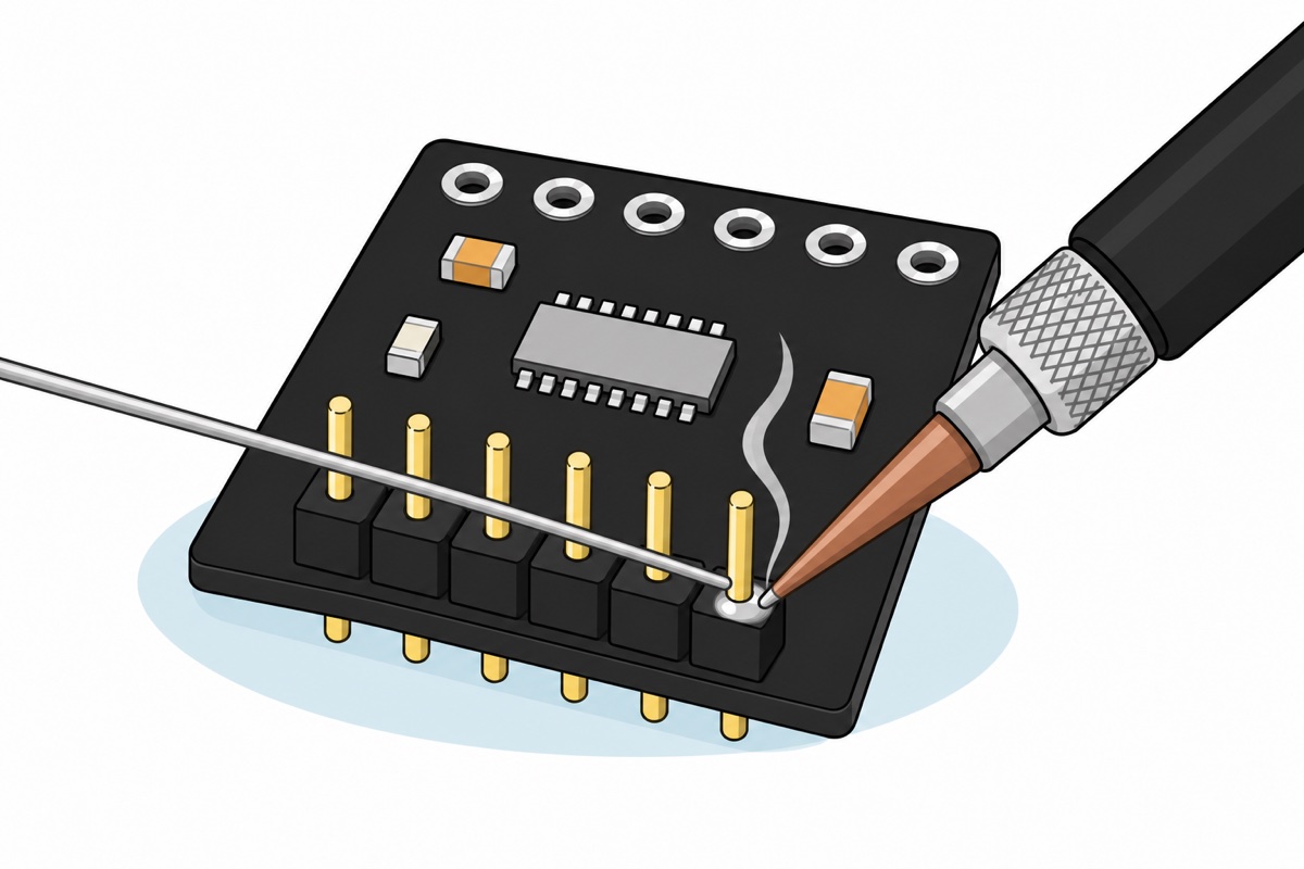
Once the pins are on, male-to-female jumpers reach from the module’s male pins to the Uno’s female headers. Match the names printed on the back of the module rather than counting positions.
| Module pin | Connects to | What it does |
|---|---|---|
| VCC | Battery + | Motor supply and chip supply in one, 2.7-10.8 V |
| GND | Battery – and an Arduino GND | Shared reference; without it the inputs float |
| IN1 / IN2 | Uno D9 / D10 | Bridge A: PWM on one, LOW on the other |
| IN3 / IN4 | Uno D3 / D11 | Bridge B, same pattern |
| OUT1 / OUT2 | Left motor’s two tabs | Bridge A output |
| OUT3 / OUT4 | Right motor’s two tabs | Bridge B output |
| EEP (nSLEEP) | Leave unconnected | Held high by the board’s own pull-up |
| ULT (nFAULT) | Optional: any Arduino input | Open drain, pulled low on a fault; use INPUT_PULLUP |
Notice which row is missing: nothing on that list powers the Arduino. An Uno’s own regulator needs about 7 V on VIN or the barrel jack before it can hold a steady 5 V rail, so one 18650 at 3.7 V runs the DRV8833 beautifully and will not run the Uno at all. On the bench, leave the Uno on its USB cable and join the two grounds — that shared ground is the whole reason the IN pins mean anything. For a robot that has to drive away untethered, feed both from a 7.4 V two-cell pack instead: 8.4 V fresh off the charger is inside the Uno’s input range and still under the DRV8833’s 10.8 V ceiling, with the PWM capped as above so the motors still average about 6 V. A two-slot holder does that in one piece, or two single holders joined positive to negative, using two cells of the same type and the same state of charge.
Mixing supplies is safe here: the DRV8833’s inputs are rated to 5.75 V in their own right, whatever VCC is doing, so an Uno’s 5 V logic is fine while the board itself runs from a 3.7 V cell. What the board has no defence against is reversed power — red to VCC, black to GND, checked before the cell goes into the holder.
You can leave EEP unconnected. On its own, the DRV8833 chip holds nSLEEP down through an internal 500 kΩ resistor, so a bare chip powers up asleep — and the module answers that with a 47 kΩ pull-up resistor from EEP to VCC, squarely inside the 20-75 kΩ TI recommends for this job. Against the chip’s 500 kΩ that holds the pin at about 91 percent of the supply — 3.4 V from a single 18650 — comfortably past the 2.5 V the chip needs to see, so the board wakes by itself. If any driver board ever sits dead with everything else correct, tie its enable pin to VCC and try again.
Direction is decided by which of a bridge’s two inputs carries the PWM. Drive IN1 with PWM and hold IN2 low and the motor turns one way; swap them and it turns the other. Both inputs high shorts the winding through the bridge, and a spinning motor is also a generator: its own voltage now drives a current round that short, and that current pulls against the rotation, which is what braking is. Both inputs low leaves the winding open with nothing to push against, so it coasts.
On an ESP32 the wiring is identical — the chip reads a logic high from 2 V, so 3.3 V outputs drive it directly — you just call ledcAttach and ledcWrite instead of analogWrite. That swap buys something real: ledcAttach(pin, 20000, 8) chops at 20 kHz, above hearing, where the Uno is stuck at 490 Hz. The faint hum a PWM-driven motor makes is that switching frequency, not a fault.
Worth seeing the board handled at real size:
The sketch below ramps both motors up, brakes, and ramps them up the other way. It deliberately uses Uno pins 9, 10, 3 and 11 rather than the obvious 5 and 6: pins 5 and 6 share their timer with millis(), so their real duty cycle lands above the number you asked for. Put one bridge on 5/6 and the other on 9/10 and the two wheels run at different speeds for the same command — a robot that curves away, and a builder who blames the motors.
// DRV8833 speed and direction test, Arduino Uno.
// Bridge A drives the left motor, bridge B the right one.
// For each bridge, one input carries the PWM and the other is held LOW.
// Swap which input carries the PWM and the motor turns the other way.
// Both inputs HIGH = brake. Both LOW = coast.

// Pins 9 and 10 sit on timer 1, pins 3 and 11 on timer 2 - both 490 Hz.
// Pins 5 and 6 are avoided on purpose: they share timer 0 with millis(),
// so their duty comes out high and the two bridges would not match.
const int AIN1 = 9;   // bridge A - timer 1
const int AIN2 = 10;  // bridge A - timer 1
const int BIN1 = 3;   // bridge B - timer 2
const int BIN2 = 11;  // bridge B - timer 2

// One 18650 sits at 3.7 V nominal, 4.2 V freshly charged, and the TT
// motors are rated 3-6 V, so full duty is safe on a single cell.
// On a 2-cell pack (7.4-8.4 V) lower this to about 185 to keep the
// average across the motor under 6 V.
const int MAX_DUTY = 255;

// speed: -255 full reverse, 0 coast, +255 full forward.
void drive(int inA, int inB, int speed) {
  if (speed >= 0) {
    digitalWrite(inB, LOW);
    analogWrite(inA, constrain(speed, 0, MAX_DUTY));
  } else {
    digitalWrite(inA, LOW);
    analogWrite(inB, constrain(-speed, 0, MAX_DUTY));
  }
}

void brake(int inA, int inB) {
  digitalWrite(inA, HIGH);
  digitalWrite(inB, HIGH);
}

void setup() {
  Serial.begin(9600);
  pinMode(AIN1, OUTPUT);
  pinMode(AIN2, OUTPUT);
  pinMode(BIN1, OUTPUT);
  pinMode(BIN2, OUTPUT);
  Serial.println(F("DRV8833 test: ramp up, brake, ramp back the other way."));
  Serial.println(F("If nothing moves, meter VCC to GND at the module first."));
}

void loop() {
  // Start at 60 rather than 0: below roughly a quarter duty the average
  // voltage cannot break the gearbox's own friction, so it only hums.
  for (int duty = 60; duty <= MAX_DUTY; duty += 5) {   // forward, ramping up
    drive(AIN1, AIN2, duty);
    drive(BIN1, BIN2, duty);
    delay(60);
  }
  brake(AIN1, AIN2);
  brake(BIN1, BIN2);
  delay(700);

  for (int duty = 60; duty <= MAX_DUTY; duty += 5) {   // reverse, ramping up
    drive(AIN1, AIN2, -duty);
    drive(BIN1, BIN2, -duty);
    delay(60);
  }
  brake(AIN1, AIN2);
  brake(BIN1, BIN2);
  delay(700);
}
If this is your first motor driver, our L298N speed control guide teaches H-bridges and PWM duty cycles step by step.
What do the DRV8833’s thermal shutdown, UVLO and overcurrent trips look like?
The DRV8833 carries three protections, and every one of them switches the outputs off and then switches them back on by itself.
| Protection | Trips when | What you see |
|---|---|---|
| Undervoltage lockout | Supply falls below about 2.6 V | Motors cut out as the cell sags, restart when it recovers |
| Overcurrent | Output exceeds the trip level: 3.3 A typical, as little as 2 A | Motor buzzes or stutters instead of turning — usually a jammed gearbox or a shorted wire |
| Thermal shutdown | The die passes about 160 °C | Everything stops after a few minutes of hard work, board is hot; it restarts once cool |
The overcurrent behaviour is the one worth understanding, because it is deliberately not instant. The chip ignores anything shorter than 4 microseconds, so the inrush spike of a motor starting does not trip it. Past that it disables the bridge for about 1.35 milliseconds and then tries again — retrying about 700 times a second, which is exactly the buzz you hear. Only the bridge that tripped is switched off — the other one carries on driving, so a robot with one jammed wheel does not stop dead, it turns in a circle.
Meanwhile ULT is pulled low on an overcurrent or a thermal trip, so an Arduino input set to INPUT_PULLUP can see that a fault happened — one flag for both, not a code telling you which. Undervoltage recovers with 90 mV of hysteresis, so a sagging battery does not make it chatter.
A board that stops and comes back is doing its job. The fix is upstream: a fresher cell, a freed gearbox, or a lower duty cycle. The case that catches people out is a cut-out at the instant the motors start, which is almost never the driver: it is the cell sagging under the starting current and dragging the supply down through the undervoltage threshold. Short, thick battery leads and a genuinely charged cell fix it.
So which one should you buy, the DRV8833 or the L298N?
Battery, small motors, tight space: DRV8833 — a line-follower, a 2WD chassis, an HC-05 Bluetooth car. Wall adapter or 12 V motors: L298N, which also wins if you want bare wires in screw terminals and no iron.
| DRV8833 | L298N | |
|---|---|---|
| Motor supply | 2.7-10.8 V | About 5 V up to 35 V |
| Supplies needed | One | One under 12 V, where the board’s own regulator makes the 5 V logic rail; above that, a separate 5 V as well |
| Lost in the bridge at 1 A | ~0.36 V | 1.8-3.2 V |
| Continuous current | 1.5 A per channel, no heatsink | 2 A per channel, with the heatsink |
| Connections | Solder 12 header pins | Screw terminals, no soldering |
| Board size | 1.8 x 2.1 cm | About 5.5 x 4.4 cm plus heatsink |
| Protections | Overcurrent, thermal, undervoltage | Thermal |
Common mistakes we see
Buying the DRV8833 for 12 V motors. The ceiling is 10.8 V and it is a hard one. A 12 V geared motor or a 12 V pump belongs on the L298N.
Expecting a 28BYJ-48 to plug in. The DRV8833 drives one bipolar stepper, one coil per bridge. The common 28BYJ-48 is unipolar as it ships and needs its own ULN2003 board instead.
Hunting for ENA and ENB. That habit comes from the L298N, where speed lives on a separate enable pin and the direction pins only go HIGH or LOW. The DRV8833 has no enable pin of that kind: speed and direction share the same two inputs, PWM on one and LOW on the other. EEP is a sleep pin, not a throttle.
Leaving the two grounds unjoined. With the motors on a battery and the Arduino on USB, the two circuits only agree on what a logic HIGH means once their grounds are wired together. Leave that one wire out and the inputs float — motors twitch, start when you touch a wire, or never move.
FAQ
Is the DRV8833 better than the L298N?
For battery projects, yes — it starts at 2.7 V and wastes about 0.36 V at 1 A instead of 1.8-3.2 V. On a wall adapter or 12 V motors the L298N is better: it accepts up to 35 V, and the DRV8833 stops at 10.8 V.
Can a DRV8833 run from a single 18650 or one LiPo cell?
Yes, and that is its strongest argument. A single cell sits between 3.0 V and 4.2 V, above the DRV8833’s 2.7 V minimum, and there is no separate logic supply to satisfy. An L298N cannot: it needs about 5 V to start and then keeps 1.8 V or more for itself.
Can the DRV8833 drive a stepper motor?
One bipolar stepper, with one coil on each of the two H-bridges. It cannot drive the common 28BYJ-48 as sold, which is a unipolar motor with a five-wire cable and wants a ULN2003 board. If you are still choosing a motor type, our stepper versus servo guide settles that first.
My DRV8833 got hot and stopped. Is it broken?
Almost certainly not. Thermal shutdown, overcurrent and undervoltage lockout all switch the outputs off and switch them back on once the cause clears. A stalled motor makes the overcurrent protection retry about every 1.35 milliseconds, which sounds like a buzz. Let it cool, free the gearbox, or drop the PWM duty.
Do I have to solder the DRV8833 module?
Yes — the twelve-pin header strip comes loose in the bag, so budget five minutes with an iron. After that the module has male pins: male-to-female jumpers reach an Arduino’s female headers, and the board straddles a breadboard channel like a chip.
Last updated September 2026. Stuck? Chat with us on WhatsApp.
