

Tutorials
Arduino 4×4 Keypad Password Lock: Wiring, Code, Lockout
Jun
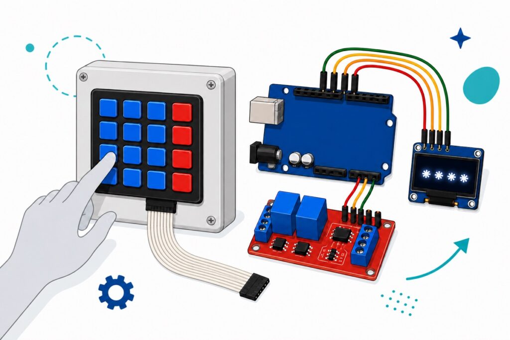
Wire the 4×4 keypad’s eight wires to pins D2–D9 on an Arduino Uno, read the keys with the Keypad library, and compare what was typed against a code stored in EEPROM — if they match, the Uno switches a relay module on for a few seconds. The most important part is not getting the code right; it is what happens after three wrong ones.
Why a keypad lock rather than RFID or a fingerprint?
A 4×4 membrane keypad gives you one thing that an RC522 RFID lock and an AS608 fingerprint lock cannot: a credential you can change and share in thirty seconds, without handing over any object and without re-enrolling anybody.
| Credential | Can it be changed? | Can it be shared remotely? | When it is lost or leaked |
|---|---|---|---|
| Keypad code | Yes, in seconds | Yes — just say it | Change the code, done |
| RFID card | Yes, but you need a new card | No — the card has to change hands | Delete the old UID, issue a new card |
| Fingerprint | No | No | Cannot be revoked |
For an RBT school project there is one more reason: a keypad carries two concepts you can defend during the viva — matrix scanning and lockout (see also our RBT electronics project ideas).
Parts list
 Arduino Uno Compatible SMD UNO R3 with Type B Cable - ATMEGA328P with CH340G-Microcontroller Project
 Matrix Array 16 Key Membrane Keypad 4 x 4 Keypad Ultra Slim Keyboard For Arduino Application
 Relay Module 3.3V 5V 12V 1/2/4/8 Ways Optocoupler Trigger Relay Module 1 2 4 8 Channel Relay Module - 5V RELAY MODULE(2WAY)
 0.96‘ OLED Display Module Blue White Screen I2C IIC Serial 128X64 LCD Display Board - 0.96' OLED WHITE
 40pcs Dupont Wire 10cm 20cm 30cm for Breadboard DIY Experiment Jumper Wire Breadboard wire - DUPONT WIRE M-M 30CM
Parts list
| Item | Price | Qty | |
|---|---|---|---|
 Power Supply Adapter DC Universal AC to DC Converter PSU 5V2A 5V3A 9V2A 12V2A - P.S. ADAPTOR (12V2A)PSA1202 Power Supply Adapter DC Universal AC to DC Converter PSU 5V2A 5V3A 9V2A 12V2A - P.S. ADAPTOR (12V2A)PSA1202 | RM15.95 | Out of stock |
A lock should not depend on a laptop. A 12V 2A adapter plugs straight into the Uno's barrel jack — 12V sits at the top end of the 7–12V range recommended for the Uno, so the board's regulator will feel warm. That is normal.
How does a 4×4 matrix keypad read 16 keys over only 8 wires?
The MEMKEYP membrane keypad has sixteen switches under its plastic layer but its tail carries only eight conductors — which is exactly why it is called a matrix. Those switches are arranged as four horizontal rows and four vertical columns, each one sitting precisely where a row crosses a column; pressing a key does nothing more than connect that row’s wire to that column’s wire.
The Arduino reads it with a technique called scanning, and this is what the Keypad library is doing behind the scenes. The four row pins are set as INPUT_PULLUP: as long as nothing is pressed, the Uno’s internal resistors hold every row up at HIGH, so the only way a row can fall to LOW is if something is pulling it down.
The Uno then drives one single column LOW at a time, while the other three are left as high-impedance inputs — electrically as good as disconnected, so no row can be pulled down through them. If a row reads LOW, there is exactly one path that LOW could have taken to get there: the switch where that row crosses the column being driven. That is the key being pressed. Repeat for all four columns, and sixteen keys are checked dozens of times a second.
The arithmetic is simple but powerful: 4 + 4 = 8 wires cover 4 × 4 = 16 keys, against 16 signal wires plus a ground if every switch were wired individually. That is the real viva answer — not “I used the Keypad library”, but “one column is driven LOW, and the row that goes down with it is the key that was pressed”.
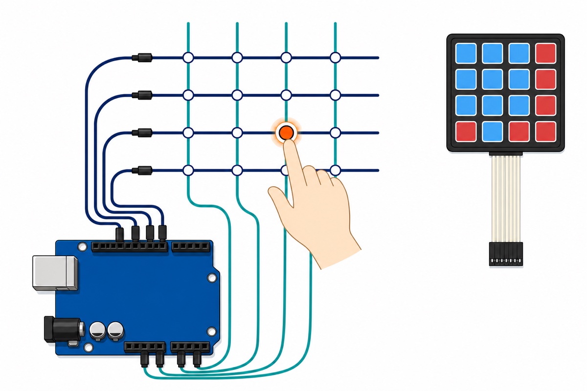
To see this pad actually wired up with the keys appearing in the serial monitor:
How do you wire the keypad, OLED and relay module to the Uno?
The MEMKEYP’s tail uses the standard 4×4 membrane pad order: counting from one end of the socket, pins 1–4 are the four rows and pins 5–8 are the four columns. Confirm which end is pin 1 with a multimeter in continuity mode — hold one key down, and the two pins that beep are that key’s row and column. The OLED shares the Uno’s I2C bus on A4 and A5, and the relay module needs one digital pin.
| Connection | Uno pin | Notes |
|---|---|---|
| Keypad pin 1 (row 1) | D9 | Row — read as INPUT_PULLUP during the scan |
| Keypad pin 2 (row 2) | D8 | — |
| Keypad pin 3 (row 3) | D7 | — |
| Keypad pin 4 (row 4) | D6 | — |
| Keypad pin 5 (column 1) | D5 | Column — driven LOW as an output during the scan |
| Keypad pin 6 (column 2) | D4 | — |
| Keypad pin 7 (column 3) | D3 | — |
| Keypad pin 8 (column 4) | D2 | — |
| OLED GND | GND | First pin on this module — check the silkscreen |
| OLED VCC | 5V | Second pin, not the first |
| OLED SCL | A5 | I2C clock |
| OLED SDA | A4 | I2C data |
| Relay DC+ | 5V | Screw terminal on the module |
| Relay DC− | GND | — |
| Relay IN1 | D10 | One pin controls one channel |
The 2WRELAY module has a selector jumper block marked Low – Com – High (with S1 and S2 columns for the two channels) beside its input screw terminals. A shunt bridging Com to Low means the module is low-level trigger: an Uno pin held LOW switches the relay on. The sketch below keeps that choice in a single constant.
Why a relay module rather than a bare relay?
The Songle SRD-05VDC-SL-C relay sitting on the 2WRELAY module has a 70 ohm coil, and 5V across 70 ohm means roughly 71 mA flows every time it pulls in (SRD-05VDC-SL-C datasheet), whereas a single Arduino Uno pin is designed for 20 mA. So a bare relay is not merely “less safe” to drive straight from a pin — it simply will not work, and the pin is at risk of damage.
The 2WRELAY module puts an optocoupler and a driver transistor between your pin and the coil: the Uno pin only lights the LED inside the optocoupler and sources a few milliamps, while the coil’s 71 mA is drawn straight from the 5V rail. A bare relay still has its place in builds that already have a driver stage of their own — see our guide on using a relay module safely. This guide stays on low-voltage DC: the side the relay switches is a 12V DC solenoid or latch, and those relay contacts are rated 10A at 30V DC. The latch is powered directly from the 12V supply through the relay contacts — not from the Uno’s 5V pin, whose regulator was never meant for a solenoid load.
The MEMKEYP’s tail ends in an 8-pin female socket and the Uno’s headers are female as well — that is why male-to-male wires are in the main parts list rather than the optional one; the same male ends can be clamped under the relay’s terminal screws. The 0.96″ OLED, meanwhile, comes with plated holes — solder a header or the wires straight into them, because a friction fit will let go on the most inconvenient day.
What happens when a wrong code is entered three times?
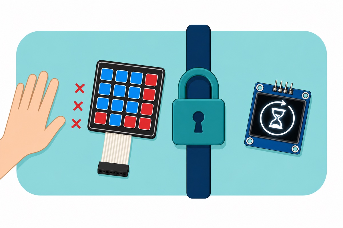
A four-digit code means 10,000 combinations, and that number sounds big until you work out how long it actually lasts. With no penalty, every failed attempt costs nothing: at one attempt every two seconds, the whole 10,000 combinations are exhausted in under six hours. Your lock’s strength is not 10,000 — it is the patience of the person standing at the pad.
A lockout turns combinations into time. After three wrong codes in a row, the sketch below stops accepting keys for 30 seconds and shows a countdown on the OLED; three more make it 60 seconds, then 120 seconds, and there it stops climbing so the owner of the box who mistypes is not locked out for hours. The penalty counter only resets after a correct code, so the sustainable rate for someone standing at the pad is three attempts every two minutes — one attempt every 40 seconds. The 10,000 combinations that were an afternoon are now more than four days.
Two more small habits, and both are free. Make the default code six digits long instead of four: a million combinations at 40 seconds each works out to more than a year, because code length and lockout multiply rather than add. And the failure message never says which digit was wrong — partial feedback is a free gift to anyone guessing, and for the same reason the OLED shows nothing but asterisks.
What does the complete Arduino sketch look like?
This sketch needs two installs in the Arduino IDE’s Library Manager: Keypad by Mark Stanley and Alexander Brevig (library reference), and Adafruit SSD1306 along with its Adafruit GFX and Adafruit BusIO dependencies. The UNOCH34 board uses the CH340 USB chip, so if no COM port appears, install the CH340 driver first.
The code is stored in EEPROM rather than in the sketch alone — that is what makes this article’s opening promise real: press A, enter the current code, type the new one, done. It survives a reset and a re-upload, because the Arduino bootloader only writes to flash and never touches EEPROM.
#include <Keypad.h>
#include <Wire.h>
#include <Adafruit_GFX.h>
#include <Adafruit_SSD1306.h>
#include <EEPROM.h>

#define SCREEN_WIDTH  128
#define SCREEN_HEIGHT 64
#define OLED_ADDR     0x3C

Adafruit_SSD1306 display(SCREEN_WIDTH, SCREEN_HEIGHT, &Wire, -1);

const byte ROWS = 4;
const byte COLS = 4;
char keys[ROWS][COLS] = {
  {'1','2','3','A'},
  {'4','5','6','B'},
  {'7','8','9','C'},
  {'*','0','#','D'}
};
byte rowPins[ROWS] = {9, 8, 7, 6};   // keypad tail pins 1-4
byte colPins[COLS] = {5, 4, 3, 2};   // keypad tail pins 5-8
Keypad keypad = Keypad(makeKeymap(keys), rowPins, colPins, ROWS, COLS);

const byte    RELAY_PIN = 10;
const uint8_t RELAY_ON  = LOW;    // shunt jumper on Com-Low; change to HIGH if Com-High
const uint8_t RELAY_OFF = HIGH;

const byte CODE_LEN = 6;                          // six digits, not four
const char DEFAULT_CODE[CODE_LEN + 1] = "246810"; // CHANGE this code after the first upload
const byte EEPROM_MAGIC = 0xA5;
const byte MAX_TRIES = 3;
const unsigned long LOCKOUT_BASE_MS = 30000UL;    // 30 s, then 60 s, then 120 s (upper limit)
const unsigned long UNLOCK_MS = 5000UL;           // how long the latch stays open

enum Mode { MODE_ENTER, MODE_OLD, MODE_NEW };
Mode mode = MODE_ENTER;

char entry[CODE_LEN + 1];
char stored[CODE_LEN + 1];
byte filled = 0;
byte wrongTries = 0;
byte penalty = 0;
unsigned long lockoutUntil = 0;
unsigned long relayOffAt = 0;
unsigned int lastShown = 0;

void loadCode() {
  // The first time the board powers up the EEPROM is still blank: plant the default code
  if (EEPROM.read(0) != EEPROM_MAGIC) {
    for (byte i = 0; i < CODE_LEN; i++) EEPROM.update(1 + i, DEFAULT_CODE[i]);
    EEPROM.update(0, EEPROM_MAGIC);
  }
  for (byte i = 0; i < CODE_LEN; i++) stored[i] = EEPROM.read(1 + i);
  stored[CODE_LEN] = '\0';
}

void saveCode() {
  for (byte i = 0; i < CODE_LEN; i++) {
    stored[i] = entry[i];
    EEPROM.update(1 + i, entry[i]);   // update() only writes the bytes that changed - EEPROM is good for ~100,000 write cycles
  }
  stored[CODE_LEN] = '\0';
}

bool matches() {
  for (byte i = 0; i < CODE_LEN; i++) {
    if (entry[i] != stored[i]) return false;
  }
  return true;
}

void resetEntry() {
  for (byte i = 0; i <= CODE_LEN; i++) entry[i] = '\0';
  filled = 0;
}

void drawPrompt() {
  display.clearDisplay();
  display.setTextSize(1);
  display.setCursor(0, 0);
  if (mode == MODE_ENTER)     display.print(F("Masukkan kod"));
  else if (mode == MODE_OLD)  display.print(F("Kod semasa"));
  else                        display.print(F("Kod baharu"));
  display.setTextSize(3);
  display.setCursor(0, 24);
  for (byte i = 0; i < filled; i++) display.print('*');   // the digits are never displayed
  display.setTextSize(1);
  display.setCursor(0, 56);
  display.print(F("* padam   A tukar kod"));
  display.display();
}

void drawBanner(const __FlashStringHelper *top, const __FlashStringHelper *big) {
  display.clearDisplay();
  display.setTextSize(1);
  display.setCursor(0, 0);
  display.print(top);
  display.setTextSize(2);
  display.setCursor(0, 28);
  display.print(big);
  display.display();
}

void drawWrong(byte left) {
  display.clearDisplay();
  display.setTextSize(2);
  display.setCursor(0, 0);
  display.print(F("KOD SALAH"));
  display.setTextSize(1);
  display.setCursor(0, 34);
  display.print(F("Baki cubaan: "));
  display.print(left);          // never reveals which digit was wrong
  display.display();
}

void drawLockout(unsigned int secs) {
  display.clearDisplay();
  display.setTextSize(2);
  display.setCursor(0, 0);
  display.print(F("TERKUNCI"));
  display.setTextSize(3);
  display.setCursor(0, 28);
  display.print(secs);
  display.setTextSize(1);
  display.print(F(" s"));
  display.display();
}

void grantAccess() {
  wrongTries = 0;
  penalty = 0;                  // the penalty counter resets only after a correct code
  resetEntry();
  digitalWrite(RELAY_PIN, RELAY_ON);
  relayOffAt = millis() + UNLOCK_MS;
  drawBanner(F("Akses"), F("DIBUKA"));
}

void wrongEntry() {
  resetEntry();
  wrongTries++;
  if (wrongTries >= MAX_TRIES) {
    if (penalty < 3) penalty++;
    lockoutUntil = millis() + (LOCKOUT_BASE_MS << (penalty - 1));
    lastShown = 0;
  } else {
    drawWrong(MAX_TRIES - wrongTries);
    delay(1200);                // a small deliberate delay
    drawPrompt();
  }
}

void submit() {
  if (mode == MODE_ENTER) {
    if (matches()) grantAccess();
    else           wrongEntry();
  } else if (mode == MODE_OLD) {
    if (matches()) {
      mode = MODE_NEW;
      resetEntry();
      drawPrompt();
    } else {
      mode = MODE_ENTER;
      wrongEntry();             // a code change counts as the same attempt
    }
  } else {
    saveCode();
    mode = MODE_ENTER;
    resetEntry();
    drawBanner(F("Kod baharu"), F("DISIMPAN"));
    delay(1500);
    drawPrompt();
  }
}

void setup() {
  digitalWrite(RELAY_PIN, RELAY_OFF);   // set the level first...
  pinMode(RELAY_PIN, OUTPUT);           // ...and only then make it an output, so the relay does not blip

  Wire.begin();
  display.begin(SSD1306_SWITCHCAPVCC, OLED_ADDR);
  display.clearDisplay();
  display.setTextColor(SSD1306_WHITE);

  loadCode();
  resetEntry();
  drawPrompt();
}

void loop() {
  unsigned long now = millis();

  // Lock again automatically after UNLOCK_MS
  if (relayOffAt != 0 && (long)(now - relayOffAt) >= 0) {
    digitalWrite(RELAY_PIN, RELAY_OFF);
    relayOffAt = 0;
    resetEntry();
    drawPrompt();
  }

  char key = keypad.getKey();   // always scanned, even when the key is discarded

  if (lockoutUntil != 0) {
    if ((long)(now - lockoutUntil) >= 0) {
      lockoutUntil = 0;
      wrongTries = 0;
      drawPrompt();
    } else {
      unsigned int left = (unsigned int)((lockoutUntil - now) / 1000UL) + 1;
      if (left != lastShown) {
        lastShown = left;
        drawLockout(left);
      }
      return;                   // every key is ignored during a lockout
    }
  }

  if (key == NO_KEY) return;

  if (key == '*') {             // clear whatever has been typed
    resetEntry();
    drawPrompt();
    return;
  }

  if (key == '#') {             // lock again immediately
    digitalWrite(RELAY_PIN, RELAY_OFF);
    relayOffAt = 0;
    resetEntry();
    drawPrompt();
    return;
  }

  if (key == 'A' && mode == MODE_ENTER && filled == 0) {
    mode = MODE_OLD;            // change the code: current code first
    resetEntry();
    drawPrompt();
    return;
  }

  if (key >= '0' && key <= '9') {
    if (filled < CODE_LEN) {
      entry[filled++] = key;
      drawPrompt();
    }
    if (filled == CODE_LEN) submit();
  }
}
After the first upload, enter the default code once, then press A and change it to a code of your own.
What are the security limits of this keypad lock?
This keypad lock is honest about itself. Shoulder-surfing is the first weakness: anyone standing behind you can watch your fingers, and no line of code fixes that — shield the pad with your hand, and mount it facing a direction that passers-by cannot easily see.
Second, worn keys. On a membrane pad, the keys pressed most often turn shiny next to their neighbours: if a four-digit code uses four different keys, that wear pattern gives away the set of digits and only the order is left — 24 orders, not 10,000. Change the code from time to time, and let your code repeat at least one digit.
Third, the code sits in the sketch as plain text. EEPROM helps — the code you sent to your teacher is no longer the code that opens the box — but anyone who can plug a programmer into the board can still read it. That is why the Uno board belongs inside the locked box.
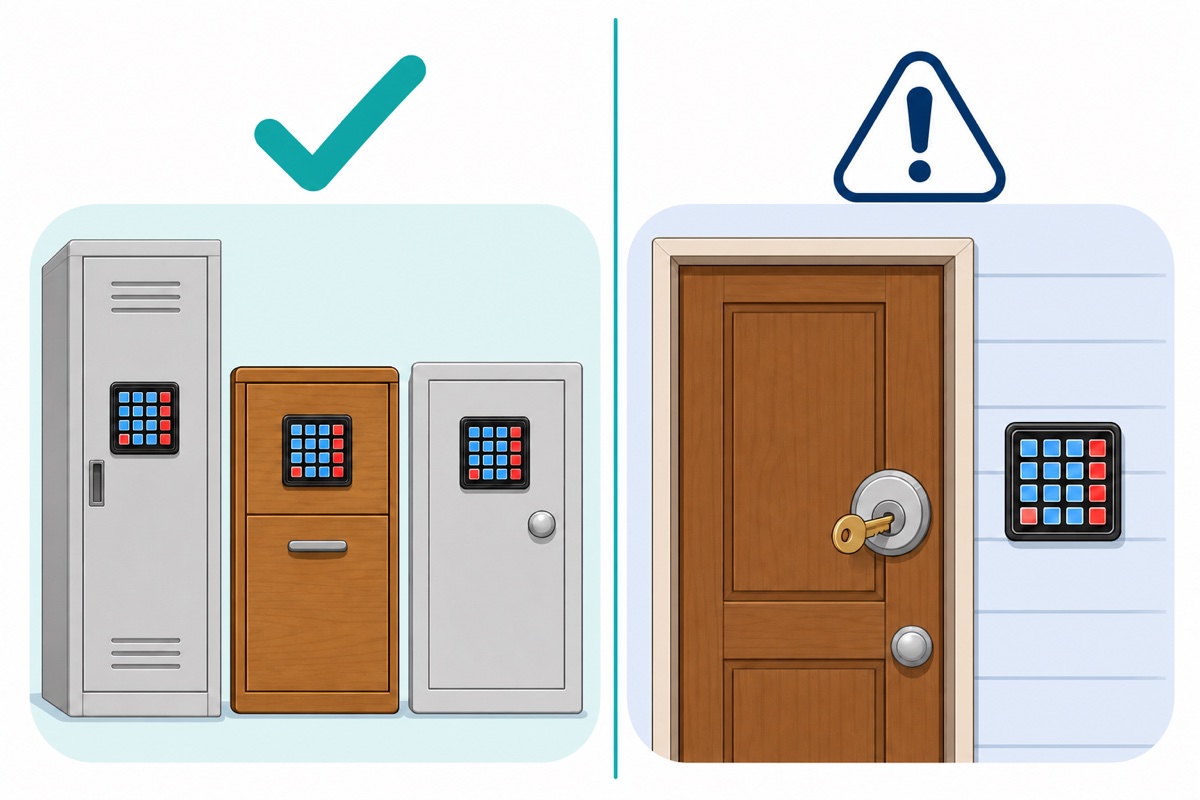
| Use | Suitable? | Why |
|---|---|---|
| School locker, desk drawer | Yes | Low value, shared access, the code can change every term |
| Component cabinet, tool box | Yes | Keeps careless hands out, not a determined intruder |
| RBT projects and exhibitions | Yes | Matrix and lockout concepts are easy to defend in a viva |
| House door | Only as an extra layer | It must sit on top of a real mechanical lock that still has a key |
That last condition is practical, not theoretical: a microcontroller can hang, power can drop, and you still need to get in. As long as a mechanical lock sits underneath, the worst failure is an inconvenience.
Common mistakes we see from customers
The pattern that reaches us most often is the row and column pin order swapped. The keypad is not dead — it just returns the wrong character, so pressing 2 gives 4 and pressing 3 gives 7, while 1, 5, 9 and D stay correct because they sit on the diagonal. The reason: the matrix is symmetrical, a switch only joins two wires, and the names row and column come from your sketch, not from the pad. So nothing is broken — swap the order of rowPins and colPins.
Second is driving a bare relay straight from a digital pin and then concluding that the relay is faulty. Third is an OLED pushed into place without being soldered: it lights up during the test on the bench, dies the moment the box is moved, and an hour disappears into checking I2C addresses for what is a mechanical problem.
Fourth, and the quietest of them: the default code is never changed. The sketch runs perfectly, the project is finished, and the box is protected by a number printed in a file shared with the whole class.
FAQ
If the power is cut, does the latch open or stay locked?
It depends on the relay terminal and the type of latch. The common DC solenoid latch is fail-secure: it needs power to open, so it stays locked when power is lost — on the NO terminal and the NC terminal alike, because the latch’s own 12V supply dies too. Wire that latch to the NO (normally open) terminal and the box stays locked through a power cut. Confirm that your latch really is fail-secure, because fail-safe latches such as electromagnets behave the other way round.
Is the code lost if the Uno resets or I re-upload the sketch?
No. The code lives in the ATmega328P’s EEPROM, and an Arduino upload only writes flash memory — the EEPROM is untouched. To force the code back to the default, change the value of EEPROM_MAGIC in the sketch and upload once.
How long should my code be?
Six digits is a good balance: a million combinations, and still easy to remember. Four digits is only ten thousand. But length on its own is not enough — pair it with the lockout, because the two effects multiply rather than add.
Can this project run on an ESP32?
Yes. The keypad only needs eight ordinary GPIOs, so the Keypad library runs as it is — change the pin numbers in rowPins and colPins, and move the OLED to GPIO21 (SDA) and GPIO22 (SCL). One difference: the ESP32 has no true EEPROM, so its EEPROM library emulates one in flash and needs EEPROM.begin() and EEPROM.commit().
Last updated August 2026. Stuck? Chat with us on WhatsApp.
