

Tutorials
Arduino Nano V3 Getting Started: Driver, IDE and First Upload
Aug
An Arduino Nano V3 goes from box to first blink in three steps: install the CH340 USB driver so the board appears as a serial port, pick Arduino Nano under Tools > Board, then set Tools > Processor — on most CH340 Nano boards that means ATmega328P (Old Bootloader). That third menu is the one nobody mentions, and it is why most first uploads fail. No soldering is needed for any of it.
The Nano V3 runs the same ATmega328P as an Arduino Uno and the same sketches. What differs is the body: an 18.5 × 43 mm stick that plants straight into a breadboard, and a Mini-USB socket instead of the Uno’s square one.
What comes in the Nano V3 box, and what else do you need?
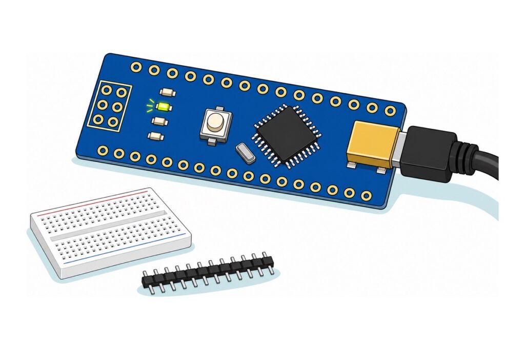
The Nano V3 with CH340 ships as a bare board: all 30 pin positions and the 2×3 ICSP block are open plated through-holes. That is deliberate: an empty hole lets you solder pins downward for a breadboard, upward for jumper wires, or at a right angle for a slim enclosure. A starter kit is therefore the board plus a 40-pin black male header strip (two 15-pin lengths snap off it, with spare) and a 400-hole breadboard. That size is the natural match: it is 85 mm long against the Nano’s 43 mm, so the board takes up about half of it and leaves the rest for the circuit.
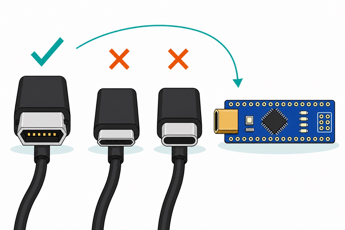
Sort the cable out before you order. The Nano’s socket is Mini-USB Type-B — the squat trapezoid with pinched-in sides, a different plug from both micro-USB and USB-C. A Mini-B lead is not part of our range, and it is the one item here you have most likely already got: Mini-B was standard on compact cameras, PS3 controllers, older hard-drive enclosures and MP3 players, so go through the drawer first. Any of those will do provided it carries data, and Mini-B leads are still sold wherever phone accessories are. Charge-only leads have no data pair, so they light the PWR LED and produce no serial port.
Parts list — the Nano, plus the headers and breadboard for step two
 Arduino NANO Compatible NANO V3 - ATMEGA328P with C340G - Mini USB - Microcontroller Project
 2.54mm Pin Header Female Male Single Row Header 40P Connector Black White Red Yellow Green Blue - 40P MALE HEADER (BLACK)
 MB102 Breadboard 170 400 830 Holes Breadboard Donut Board Arduino Prototype Multi Color - BREADBOARD (400 HOLES)
Parts list
 50g Soldering Wire Lead with Flux Core 1mm Diameter
 80W Electronics Soldering Iron with LCD Display Ajustable Temperature Microconstroller Electronic Project
 40pcs Dupont Wire 10cm 20cm 30cm for Breadboard DIY Experiment Jumper Wire Breadboard wire - DUPONT WIRE M-M 20CM
 Nano Expansion Shield For Arduino NANO R3
Only for the soldering step and what comes after it — skip the iron and solder if you already own them. The Nano expansion shield is the alternative route once your headers are on.
How do you make the CH340 show up as a serial port?
The CH340G on this Nano is a USB-to-serial bridge: the ATmega328P speaks plain asynchronous serial, your computer speaks USB, and the CH340 translates. Your computer needs a driver to claim the chip and present it as a virtual COM port — without one the board draws power, the PWR LED lights, and nothing else happens.
That one chip is also what “Arduino Nano compatible” means. A compatible Nano carries the same ATmega328P, the same 16 MHz crystal, the same pin order and the same Arduino core as an original — what the factory changes is the USB-to-serial chip, fitting the WCH CH340G in place of the FTDI FT232RL the original Nano was built around. Both awkward steps in this article fall out of that one substitution: Windows has no CH340 driver in the box, and the board arrives carrying whichever bootloader the factory flashed rather than the one Arduino ships.
Have the Arduino IDE on the machine first — the free desktop IDE from arduino.cc. Either 1.8.x or 2.x is fine; both carry the Processor menu this article turns on. The driver then depends on the operating system:
- Windows — install CH341SER from WCH, the chip’s own maker. Click INSTALL (the dialog’s only other buttons are UNINSTALL and HELP), then replug the board.
- macOS — nothing to install: Apple has shipped its own AppleUSBCHCOM driver for CH34x chips since macOS 10.14 Mojave. The port appears as
/dev/cu.usbserial-…; only if you have installed WCH’s own Mac driver instead does it read/dev/cu.wchusbserial…. - Linux — nothing to install either;
ch341is in the kernel. The port is/dev/ttyUSB0; if it is missing from the IDE’s list, you are not in thedialoutgroup.
Verify the driver instead of assuming it. A real binding appears and disappears with the hardware, so the test is a replug: watch the Ports section of Windows Device Manager (or the IDE’s port list on Mac and Linux), unplug the Nano, and one entry must vanish and return when you plug it back in. An entry that stays put with the board out belongs to something else, and a yellow warning triangle means the driver never bound. Whichever entry came and went is the Nano, so tick that one under Tools > Port: the IDE uploads to the port selected in the menu, not to whatever happens to be plugged in. The CH340 does not identify the board behind it, so expect a bare COM5 or /dev/cu.usbserial-1420 with no board name — the missing word “Arduino” is normal, not a fault. Our not-detected troubleshooting guide works the same fault through on ESP32 boards.
Why does the Nano need “Old Bootloader” under Tools > Processor?
The bootloader is a small program living in a reserved block at the top of the ATmega328P’s flash that runs for a moment every time the chip resets. In that moment it listens on the serial port: if the IDE is talking, it writes the incoming sketch into flash; if nobody is talking, it hands control to the sketch already there. That is the whole reason a Nano programs over a USB cable rather than with a separate programmer. You never touch the reset button for any of it: when the IDE opens the port it drops the CH340’s DTR line, and a small capacitor passes that falling edge through to the ATmega328P’s reset pin. The same circuit is why opening the Serial Monitor restarts your sketch from the top.
Two bootloaders are in circulation and they listen at different speeds. Set Tools > Board > Arduino AVR Boards > Arduino Nano, and the Processor menu below offers ATmega328P and ATmega328P (Old Bootloader). In the Arduino AVR core’s own boards.txt the first uploads at 115200 baud and expects the newer Optiboot; the second uploads at 57600 baud and expects the older ATmegaBOOT. Most CH340-based Nano boards ship with the older one.
The IDE cannot work out which one you have, and that is precisely why this is a menu you set by hand rather than something automatic. The bootloader sits inside the ATmega328P’s own flash and announces nothing about itself, and the CH340 in front of it is a generic serial bridge with no idea what is on its other side. So the uploader has to be told what speed to open the conversation at, and if it is told the wrong one the two ends never meet.
Everything else about the two entries is identical — same ATmega328P compile target, same 2048 bytes of RAM, same 30720-byte sketch ceiling. The only thing the dropdown changes is the uploader’s baud rate, which makes the failure very specific: at the wrong speed the bootloader samples correctly-shaped voltage transitions at the wrong bit timing, decodes garbage, and never returns the synchronisation byte the uploader waits for. The IDE prints ten failed attempts, counting up from the first:
Warning: attempt 1 of 10: not in sync: resp=0x00Older Arduino IDE versions word the same fault as avrdude: stk500_getsync() attempt 1 of 10: not in sync: resp=0x00, because the uploader’s wording changed along the way. Either way, not in sync: resp=0x00 is the part that identifies it.
That message is good news. To print it at all, avrdude had to open the serial port — so the driver bound, the cable carries data and the port choice was right. Only the Processor dropdown stands between you and a working board. Try the other entry; nothing is harmed by guessing wrong.
| What happens | What it means | What to change |
|---|---|---|
| No port in the list at all | Driver not bound, or a charge-only cable | Install CH341SER, replug, try a known data cable |
Port appears, upload gives not in sync: resp=0x00 |
Wrong bootloader baud rate | Switch Tools > Processor to the other ATmega328P entry |
| Port appears then vanishes mid-upload | Cable or USB hub dropping the link | Direct port on the computer, different cable |
Both Processor entries give not in sync |
Nothing is listening — the reserved bootloader block is empty or damaged | Reflash the bootloader through the 2×3 ICSP holes with a second Arduino as ISP, or message us |
| Upload reports success, board does nothing | Upload was fine; the sketch is the problem | Load the blink sketch below as a known-good reference |
What should the first sketch be?
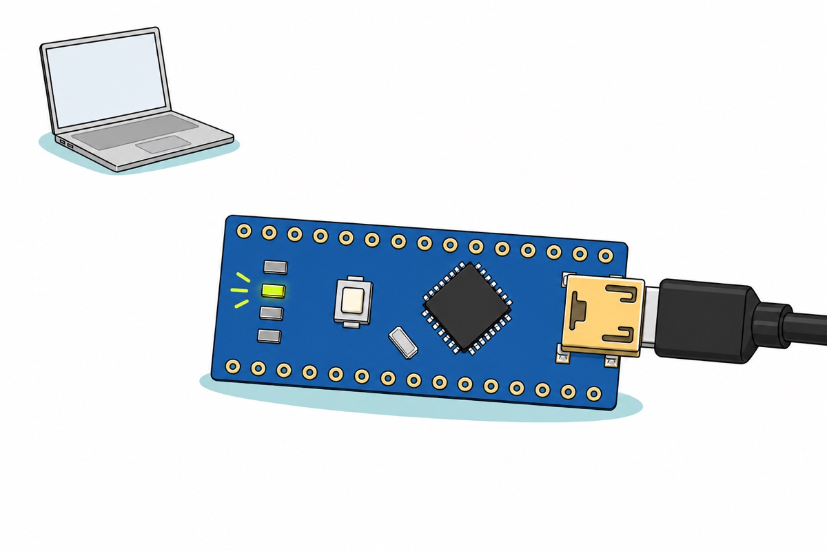
The Nano carries an LED on pin D13, silkscreened L — one of the four small SMD lamps beside the reset button. It is already wired to that pin, so the first upload needs no headers, no breadboard and no components. This sketch blinks it and prints over the serial link too, so one upload proves both directions of the connection.
// First upload test for an Arduino Nano V3 (ATmega328P + CH340).
// Needs NO soldering and NO extra parts: it blinks the LED already on the
// board and talks back over the same USB cable that programmed it.

const uint8_t LED_PIN = LED_BUILTIN;  // D13 on the Nano - the pin the onboard L LED sits on
const unsigned long BLINK_MS = 500;   // half a second on, half a second off

unsigned long lastToggle = 0;
bool ledOn = false;
unsigned long beats = 0;

void setup() {
  pinMode(LED_PIN, OUTPUT);
  Serial.begin(9600);   // Serial Monitor must be set to this same 9600 baud
  Serial.println(F("Nano is alive. If you can read this, USB, CH340 and the bootloader all work."));
}

void loop() {
  unsigned long now = millis();

  // millis() instead of delay(): the board stays free to do other work between blinks
  if (now - lastToggle >= BLINK_MS) {
    lastToggle = now;
    ledOn = !ledOn;
    digitalWrite(LED_PIN, ledOn ? HIGH : LOW);

    if (ledOn) {                       // one line per full blink, not two
      beats++;
      Serial.print(F("blink "));
      Serial.print(beats);
      Serial.print(F("  uptime "));
      Serial.print(now / 1000);
      Serial.println(F(" s"));
    }
  }
}
Set Serial Monitor’s baud selector to 9600 to match Serial.begin(9600). Mismatch it and you get the same class of failure as the bootloader dropdown: neat rows of meaningless characters, because the bits arrive at a rate the receiver is not sampling at.
When do you solder the headers on?
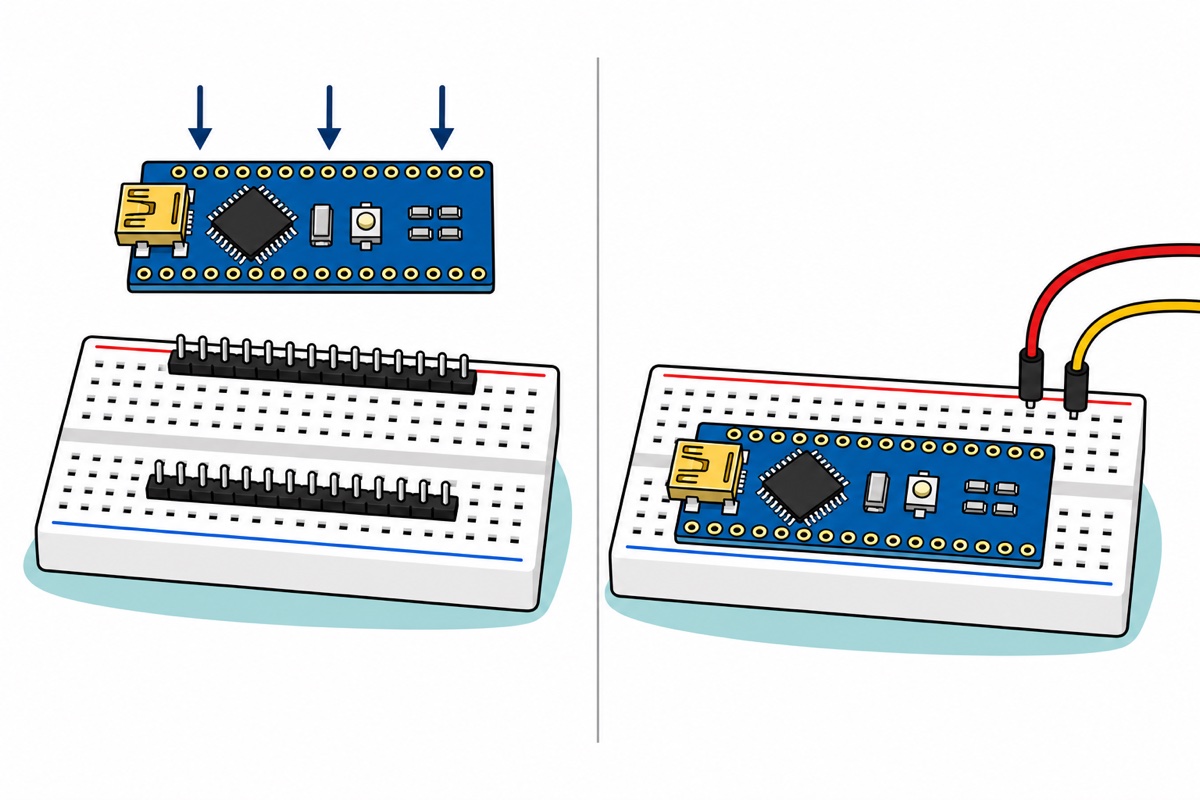
The Nano’s header pins are step two, once the board has proved itself. Snap two 15-pin lengths off the 40-pin black strip — it is scored between every pin — and use the breadboard as a jig: push both strips into it, drop the Nano over the protruding pins, and the breadboard holds all 30 perpendicular while you solder. Straight pins are not cosmetic; a strip soldered at a lean will not seat in a breadboard afterwards. The iron tip sits in the hundreds of degrees and burns on contact, so park it in its stand between joints, never on the bench.
Our header soldering guide covers the technique, and choosing an iron and flux the tools. Watching the motion helps more than reading it:
Seated pins-down, the Nano straddles the breadboard’s centre channel. Its two header rows are 0.6 inch apart while the channel between the two banks of tie points is only 0.3 inch wide, so the Nano can never sit centred on it: the body of the board overhangs the holes on both sides and buries most of them on one side. A terminal strip has ten hole columns and the Nano covers five of them, so pushed hard against one bank it leaves four reachable tie points in line with every pin on the open side and a single one on the buried side. Choose that offset as you seat the board — the open side is where the whole circuit has to live. Run it out with male-to-male jumper wires; our jumper wire guide covers which ends mate with what. The Nano expansion shield is the alternative — it takes the board pins-down into black sockets and re-presents every I/O as a ground/voltage/signal block — but it needs those headers soldered first, so it is a step three, not a way around step two.
Settle one thing before you hang parts off those tie points: the Nano’s 5V pin is an output as well as an input, and it is what feeds the breadboard’s red rail — but it is not a bottomless supply. Running on USB, everything on that rail is drawn from the computer’s port, and a standard USB 2.0 socket allows 500 mA for the board and your circuit together. Running on VIN, the 5 V comes from the onboard linear regulator, which does not convert the surplus voltage — it burns it: at 12 V in, every 100 mA you draw turns 0.7 W into heat in a package a few millimetres across, so it runs hot and folds back well short of any headline figure. The 3V3 pin is a low-current reference, not a second rail. The 20 mA per-pin limit is a third budget, separate from both — an I/O pin switches a transistor or a driver module; it does not drive the load itself. Anything with a motor, a heater or a long LED strip in it gets its own supply, with the two grounds joined.
Nano or Uno — which should you actually buy?
The Nano V3 and the Uno R3 carry the same ATmega328P at 16 MHz with the same 32 KB flash, 2 KB SRAM and 1 KB EEPROM and the same 20 mA per-pin limit, and a sketch written for one compiles unchanged for the other. The choice is about the body the chip is packaged in, not capability.
| Nano V3 | Uno R3 | |
|---|---|---|
| Footprint | 18.5 × 43 mm — fits inside most project enclosures | 53 × 69 mm — usually needs its own box |
| Breadboard | Plants directly into it, pins down | Sits beside it, wired over with jumpers |
| Ready on arrival | Headers to solder first for anything past USB | Female sockets already fitted, no soldering ever |
| Shields | None — the shield format does not fit | Takes the whole Uno shield ecosystem |
| Analog inputs | 8 (A0–A7) | 6 (A0–A5) |
| USB plug | Mini-USB Type-B | The large square Type-B printer plug |
Those two extra analog inputs come with a condition. A6 and A7 exist only on the surface-mount ATmega328P package the Nano uses, and they are wired straight to the analog-to-digital converter’s multiplexer without passing through any port register. They read fine with analogRead() and can do nothing else — no digitalWrite(), no digitalRead(), no INPUT_PULLUP. Treat them as sensor inputs, never as spare pins.
So: the Nano for anything small, breadboarded or boxed; the Uno if you would rather not solder anything to get started, or if the project is built around shields. Weighing whole board families instead? Our ESP32 vs ESP8266 vs Uno comparison covers that layer.
Common mistakes we see
Blaming the driver for a Processor-menu fault. A driver fault means no port exists to select; a Processor fault means the port is there, avrdude opens it, and the sync attempt fails. If you can see the port, stop reinstalling drivers.
Using a charge-only Mini-B cable. No data pair still means a lit PWR LED, which reads as a working connection. The giveaway is that no port ever appears.
Soldering headers before the first upload. It costs you the cleanest possible test: a board that fails a bare-board blink is faulty on arrival, with no soldering of yours in the picture to argue about.
Soldering the header strips the wrong way up. A male strip has a long end and a short end. The long pins go down into the breadboard, so the black plastic spacer ends up trapped between the Nano and the breadboard, and you solder the short ends poking through the top face. Fit a strip the other way round and there is not enough pin left under the board to reach a tie point.
Expecting A6 or A7 to drive something. digitalWrite(A6, HIGH) compiles without complaint and the pin never moves, because there is no digital output hardware behind it — the AVR core’s pin tables run only as far as A5, with no entry for A6 or A7 at all.
FAQ
Which cable does an Arduino Nano V3 use?
Mini-USB Type-B — a squat trapezoid, not micro-USB and not USB-C. Compact cameras, PS3 controllers and older hard-drive enclosures used the same plug. It must carry data; charge-only leads produce no serial port.
Do I have to solder the Nano’s headers before I can use it?
Not for the first upload. The L LED on D13 is already wired on the board, so blink runs over USB alone. Headers are needed only to reach the I/O pins — breadboard, jumper wires or the expansion shield.
Why does my Nano say “not in sync: resp=0x00”?
Almost always the Processor dropdown. Most CH340 Nano boards use the older ATmegaBOOT bootloader, which listens at 57600 baud, while the plain ATmega328P entry uploads at 115200. Switch Tools > Processor to ATmega328P (Old Bootloader).
Is the Arduino Nano as powerful as an Uno?
Identical — same ATmega328P at 16 MHz, same 32 KB flash, 2 KB SRAM, 1 KB EEPROM, same sketches. The Nano adds analog-read-only A6 and A7; the Uno gains shield compatibility and pre-fitted sockets.
Can the Nano run from a battery instead of USB?
Yes. Feed 7–12 V into VIN and the onboard regulator makes the 5 V rail — a 9 V battery or a six-cell AA holder suits it. A four-cell pack is the common miss: at 6 V nominal it already sits below that range and falls from there, leaving the regulator too little headroom to hold 5 V. Never feed VIN’s 7–12 V into the 5V pin, which sits after the regulator.
Last updated August 2026. Stuck? Chat with us on WhatsApp.
