

Tutorials
RC522 RFID Door Lock with Arduino: The Honest Tutorial
Jun
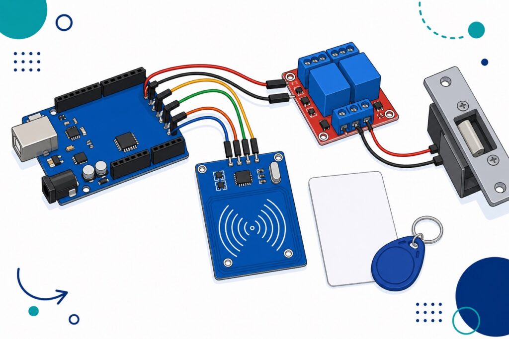
Wire the RC522 to the Arduino Uno’s SPI pins, read a card’s UID, compare it against a list inside your sketch, then pulse a relay module that switches a 12V electric strike. The RC522 is a 3.3V device — its VCC goes to the Uno’s 3.3V pin, never 5V. One library, one sketch, about ten wires.
What comes in the RC522 kit, and what does it actually read?
The RC522 is sold here as a full set: the blue reader PCB with its large spiral antenna coil etched into the copper, one white RFID card, one blue teardrop keyfob, and two loose pin-header strips — one straight, one right-angle. Nothing is pre-soldered — our header pin soldering guide walks through fitting whichever header suits your enclosure.
The reader works at 13.56 MHz on the ISO/IEC 14443A standard — the MIFARE family, which covers the card and fob in the box plus many office and condo access cards — though not the older 125 kHz type, which this reader cannot see at all.
Parts list
 Arduino Uno Compatible SMD UNO R3 with Type B Cable - ATMEGA328P with CH340G-Microcontroller Project
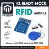 RFID Full Set Sensor Module 13.56MHz RC522 Card Reader with RFID Card, RFID button Arduino IOT
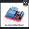 Relay Module 3.3V 5V 12V 1/2/4/8 Ways Optocoupler Trigger Relay Module 1 2 4 8 Channel Relay Module - 5V RELAY MODULE(2WAY)
 Power Supply Adapter DC Universal AC to DC Converter PSU 5V2A 5V3A 9V2A 12V2A - P.S. ADAPTOR (12V2A)
How do you wire the RC522 and relay to an Arduino Uno?
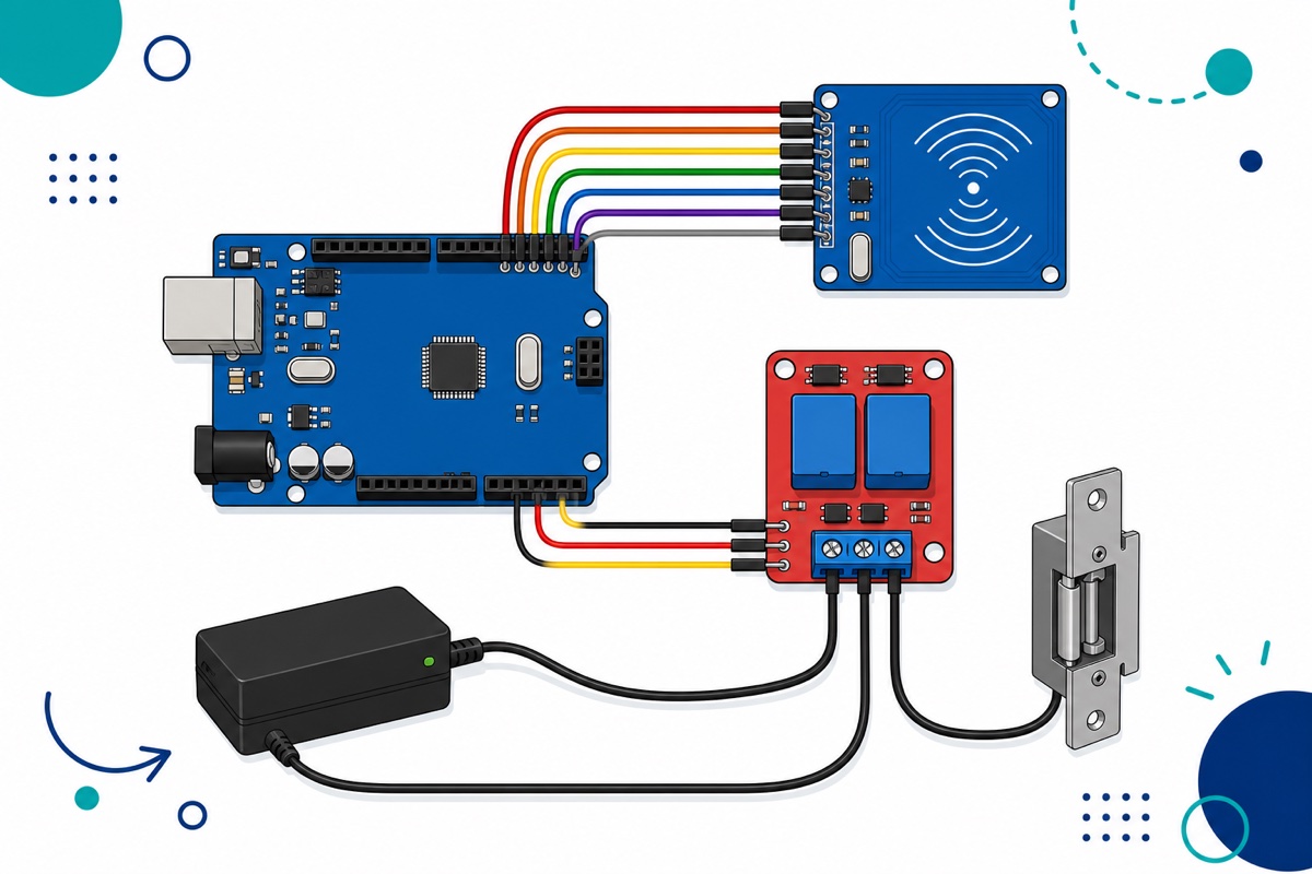
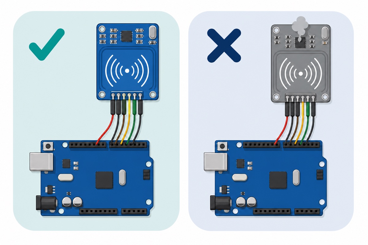
The RC522 talks SPI, so it lands on the Uno’s fixed hardware SPI pins, and the MFRC522 library expects exactly this layout. Leave IRQ unconnected.
| Module pin | Arduino Uno | Notes |
|---|---|---|
| RC522 SDA (SS) | D10 | Chip select; labelled SDA on this board |
| RC522 SCK | D13 | SPI clock |
| RC522 MOSI | D11 | SPI data out |
| RC522 MISO | D12 | SPI data in |
| RC522 RST | D9 | Reset |
| RC522 VCC | 3.3V | Never 5V — 5V here destroys the module |
| RC522 GND | GND | Shared ground |
| Relay IN1 | D7 | Any spare digital pin |
| Relay DC+ | 5V | Coil and opto supply |
| Relay DC− | GND | Shared ground |
That 3.3V line is the one rule with no forgiveness: the chip’s absolute maximum on every supply pin is 4.0V, so 5V on VCC kills it — the most common way people destroy one of these readers. The logic pins are not officially 5V-tolerant either — the datasheet caps them at 0.5V above the supply, about 3.8V — and while these modules routinely shrug off the Uno’s 5V SPI signals in practice, a level shifter or simple series resistors are the by-the-book fix.
The lock stays a separate low-voltage circuit: 12V supply positive into the relay’s COM terminal, NO out to the strike, strike back to the 12V negative. The second relay channel stays spare.
Why does this build use a relay module instead of a bare relay?
The Songle SRD-05VDC-SL-C relay is the blue cube on that red board, and we sell it as a bare component for builds with their own driver stage — but no bare relay, ours or anyone’s, can be driven straight from an Arduino pin. Its 5V coil measures 70 Ω, so it pulls about 71 mA while a Uno I/O pin is rated for 20 mA, and switching the coil off kicks back a spike that will eventually take the pin with it.
A bare relay therefore needs a driver transistor and a flyback diode built around it. The 2-channel module carries both, plus an optocoupler on each input — which is exactly why it is the part in this build. Your pin only drives an opto LED at a few milliamps; the module handles the coil.
How do you stop the lock clicking open when the Arduino resets?
The 2-channel relay module carries a small jumper block beside the input terminal marked for high or low level trigger, which decides the logic level that pulls the relay in. That matters on a lock: during power-up and reset the Uno’s pins float as inputs, a floating input can read LOW, and on low-level trigger the lock clicks open every time someone power-cycles the board.
Two habits fix it: choose the trigger side deliberately, since high-level trigger keeps a floating pin harmless, and set the pin’s idle state first thing in setup(), writing the idle level before pinMode(). Our relay module safety guide covers the jumper in depth. Keep the lock on low-voltage DC with its own supply — mains switching does not belong in this build.
How do you find your card’s UID and run the sketch?
The MFRC522 library by GithubCommunity is the one to install: Arduino IDE Library Manager, search MFRC522, pick that entry. Upload the sketch below unchanged, open Serial Monitor at 9600 baud and tap your card — it prints the UID of every card it sees, allowed or not. Copy those bytes into allowedUids, re-upload, and that card now opens the lock.
#include <SPI.h>
#include <MFRC522.h>

#define SS_PIN     10   // RC522 SDA/SS
#define RST_PIN     9   // RC522 RST
#define RELAY_PIN   7   // Relay module IN1

// Match these to your trigger jumper: LOW/HIGH for low-level trigger,
// HIGH/LOW for high-level trigger.
#define RELAY_ACTIVE  HIGH
#define RELAY_IDLE    LOW
#define UNLOCK_MS   3000

MFRC522 mfrc522(SS_PIN, RST_PIN);

// Allowed cards, 4-byte UIDs. Replace these with the UIDs this sketch prints.
byte allowedUids[][4] = {
  {0xDE, 0xAD, 0xBE, 0xEF},
  {0x12, 0x34, 0x56, 0x78}
};
const byte allowedCount = sizeof(allowedUids) / sizeof(allowedUids[0]);

// Returns true only if the tapped UID matches a whole row of the list.
bool isAllowed(byte *uid, byte size) {
  if (size != 4) return false;          // this list holds 4-byte UIDs only
  for (byte c = 0; c < allowedCount; c++) {
    byte matched = 0;
    for (byte i = 0; i < 4; i++) {
      if (uid[i] == allowedUids[c][i]) matched++;
    }
    if (matched == 4) return true;
  }
  return false;
}

void setup() {
  // Park the relay BEFORE the pin becomes an output, so it never
  // glitches to the active level while the board is starting up.
  digitalWrite(RELAY_PIN, RELAY_IDLE);
  pinMode(RELAY_PIN, OUTPUT);
  digitalWrite(RELAY_PIN, RELAY_IDLE);

  Serial.begin(9600);
  SPI.begin();
  mfrc522.PCD_Init();
  delay(50);
  mfrc522.PCD_DumpVersionToSerial();  // 0x00 or 0xFF means wiring or power trouble
  Serial.println(F("Ready. Tap a card."));
}

void loop() {
  if (!mfrc522.PICC_IsNewCardPresent()) return;
  if (!mfrc522.PICC_ReadCardSerial()) return;

  // Print the UID of every card, so you can harvest your own.
  Serial.print(F("UID:"));
  for (byte i = 0; i < mfrc522.uid.size; i++) {
    if (mfrc522.uid.uidByte[i] < 0x10) Serial.print(F(" 0"));
    else Serial.print(F(" "));
    Serial.print(mfrc522.uid.uidByte[i], HEX);
  }
  Serial.println();

  if (isAllowed(mfrc522.uid.uidByte, mfrc522.uid.size)) {
    Serial.println(F("Granted - unlocking"));
    digitalWrite(RELAY_PIN, RELAY_ACTIVE);
    delay(UNLOCK_MS);
    digitalWrite(RELAY_PIN, RELAY_IDLE);
  } else {
    Serial.println(F("Denied"));
  }

  mfrc522.PICC_HaltA();
  mfrc522.PCD_StopCrypto1();
}
How secure is RC522 access control, honestly?
The UID this RC522 sketch compares is not a secret. A card broadcasts it to any reader that asks, before any authentication happens, and blank cards whose UID block can be rewritten are sold openly for a few ringgit. The MFRC522 library’s own documentation says it plainly: a UID cannot be used as unique identification for security-related projects.
Reading a protected sector instead does not rescue it. MIFARE Classic’s Crypto1 cipher has been publicly broken since 2008, and researchers later showed a ciphertext-only attack recovering keys from a hardened card in minutes. In 2024 Quarkslab found a hardware backdoor key shared across a whole family of MIFARE Classic compatible chips. Crypto1 is not weak; it is finished.
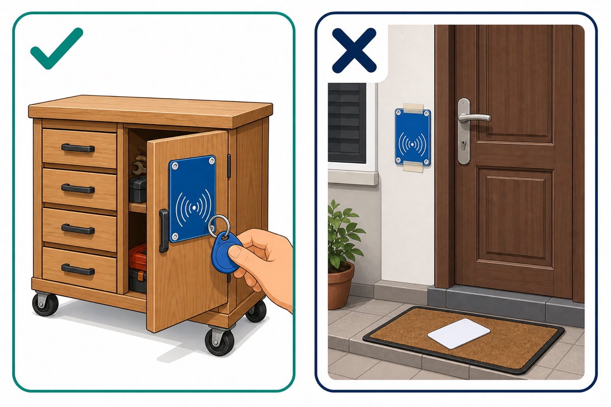
The honest verdict, then — and it is no reason to stop building. This is an excellent RBT or final-year project, an attendance or access log, a drawer, a locker, a workshop cabinet, a “who is at the bench” display, or a gate that keeps a physical key as backup. It is not the lock for your front door, your safe, or anything you would be upset to lose.
When the threat model is real, the credential has to be. Cards like MIFARE DESFire use AES-128 with mutual authentication instead of a broadcast serial number, and that is what commercial door systems run on. For a home’s front door, a good mechanical lock plus a camera beats UID matching every time.
Why does the reader see nothing, or read but never match?
The RC522 has few failure modes and each has a signature — which is why the sketch prints the firmware version on every boot.
| Symptom | Likely cause | Fix |
|---|---|---|
| Firmware version prints 0x00 or 0xFF | SPI wiring wrong, or 5V on VCC | Recheck D9–D13, move VCC to 3.3V; a module already fed 5V may be dead |
| Version reads fine, no card ever detected | Unsoldered or cold header joints | Reflow the eight joints; wiggle-testing wires proves nothing |
| Reads work, then stop after a few taps | Weak 3.3V or long jumper wires | Shorten wires below 20 cm, power the Uno from a proper supply, not a laptop hub |
| UID prints but access is always denied | Byte or length mismatch in the list | Copy the printed bytes exactly; 7-byte UID cards need the length check widened |
Common mistakes we see from real customers
The pattern that costs money is an RC522 wired to 5V out of habit, because every other module runs on 5V. The failure then shows up as a 0x00 firmware version on a board that worked an hour earlier — followed by an afternoon spent doubting perfectly good code.
The pattern that costs an evening is a strike that disagrees with the design: bench-tested with the relay clicking happily, then fitted to a fail-secure lock when the plan assumed fail-safe. Decide what should happen during a power cut before you buy the strike.
FAQ
Can I use the RC522 to clone my office access card or Touch ‘n Go?
An RC522 can usually read the UID of any 13.56 MHz card, and Touch ‘n Go sits on the same MIFARE family — but we will not publish a cloning procedure. Duplicating a credential you do not own is a matter for whoever issued it, and stored-value balances live in encrypted sectors that are not yours to touch.
Does the RC522 read through a door or wall?
It reads through a few millimetres of non-metallic material — wood, acrylic, or a 3D-printed faceplate — which is how you hide the reader inside an enclosure. Metal is the killer: a metal door or backing plate detunes the antenna and the range collapses.
What is the actual read range of the RC522?
Up to 50 mm on paper, and a realistic 2–4 cm with the bundled white card. The blue keyfob’s smaller antenna reads shorter still, and range drops further on a sagging supply.
Can I use an ESP32 instead of the Arduino Uno?
Yes, and electrically it is a better match, because the ESP32 is a 3.3V board like the RC522. Use the default SPI pins — MOSI 23, MISO 19, SCK 18, SS 5 — with RST on any free GPIO. Our ESP32 vs ESP8266 vs Uno comparison covers the trade-offs.
How many cards can I store in the allowed list?
Far more than you need. Each 4-byte UID costs four bytes of the ATmega328P’s 2 KB of RAM, so hundreds fit in the array. Move the list into the chip’s 1 KB EEPROM — roughly 250 UIDs — when cards should survive a power cut and be enrolled without re-uploading.
Last updated August 2026. Stuck? Chat with us on WhatsApp.
