

Tutorials
TT Gear Motor for Beginners: What It Is, Wiring and Real Speed
Nov
The TT gear motor is the yellow 3–6V gearbox motor on almost every beginner robot car: inside, a small brushed motor spins at roughly 9,600 RPM and a 1:48 plastic gear train trades that speed for torque, leaving about 200 RPM at the shaft at 6V with no load. It never wires straight to an Arduino pin — even spinning free it draws several times what a pin can safely supply, so a motor driver such as the L298N sits in between — and its dual-flat shaft push-fits the standard 68mm yellow robot wheel.
What is a TT gear motor?
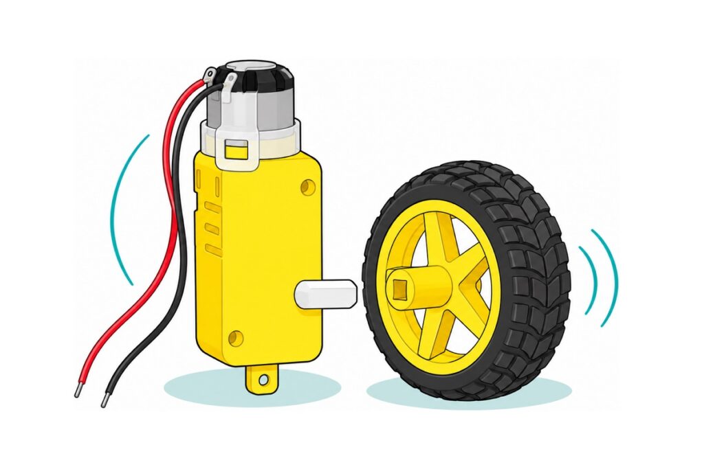
The TT gear motor is a small DC motor and its gearbox sold as one part: a bright yellow plastic case with corner mounting lugs, a silver motor can at the rear held by a translucent white bracket, and a white output shaft with two flat sides protruding from both sides of the body. The can is an ordinary 130-size brushed motor, the same small can found in battery-powered toys; everything special about the part is the gear train in the yellow box.
Treat 3–6V as the working range. Voltage sets both how fast the can spins and how hard it shoves when a wheel jams — Adafruit’s figures show stall torque doubling from 3V to 6V. Past 6V that extra shove lands on plastic teeth and the extra current wears the tiny brushes faster, so a little speed now costs stripped gears later — our pre-wired TT motor with leads is rated 3–6V. The plain version has no feedback: power in, rotation out.
Parts list: TT motor first spin (both wheels)
 TT MOTOR WITH WIRE 3-6V DC 200RPM 1:48 GEARBOX MOTOR WITH WIRES PRE-SOLDERED
 200RPM TT MOTOR With 68mm Wheel 3V 5V 6V 9V Motor Plastic Gear Motor For Arduino Smart Car - WHEEL (FOR TT MOTOR)
 L298N Motor Driver Module Arduino Compatible Dual H Bridge Dual DC Motor Control Arduino Robotic Car
 Arduino Uno Compatible SMD UNO R3 with Type B Cable - ATMEGA328P with CH340G-Microcontroller Project
 40pcs Dupont Wire 10cm 20cm 30cm for Breadboard DIY Experiment Jumper Wire Breadboard wire - DUPONT WIRE M-F 30CM
 18650 Battery Holder 1/2/3/4 Slot 3.7V Battery Cell Housing Battery Case Battery Casing - 18650 BATTERY HOLDER (2)
 3.7V 18650 Battery Rechargeable Li-Ion Battery 1200mAh 2200mAh 3200mAh Flat Top - 18650 Li-Ion Battery (2200mAh)
Optional: turn the bench test into a car
 2WD 4WD Smart Car Chassis Single Layer Acrylic Arduino Smart Car Chassis Kit With Motor - 2WD CAR KIT
 Ball Caster Wheel Ball Transfer Eye Ball Roller Caster Bull Eye Wheel For Arduino Smart Car
 18650 Battery Charger 1/2 Slot Li-on Battery Charger USB A Connector 3.7V Universal Charger - 18651 BATTERY CHARGER (2 SLOT)
The 2WD chassis kit brings its own 2 TT motors, 2 wheels, a swivel caster, a 4xAA holder and mounting hardware, so it can replace the motor and wheel rows above if you can solder: its motors have bare tabs and loose leads. Keep the 18650 pack over its AA holder. The steel ball caster suits a scratch-built chassis, and the charger tops up the two 18650 cells between runs.
What do the 1:48 ratio and 200 RPM actually mean?
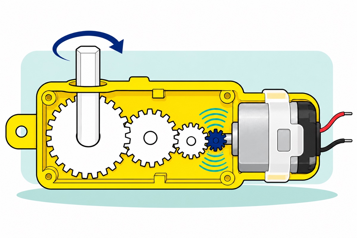
On a TT motor, the 1:48 ratio means the motor can turns 48 times for one turn of the output shaft — so 200 RPM (revolutions per minute) at the shaft × 48 = about 9,600 RPM at the can, speed with almost no twist: fingers can stop a bare can. Each gear stage is a small gear driving a bigger one, and the same tooth force acting at the bigger gear’s larger radius means more torque at fewer turns. The stages divide speed by exactly 48 and multiply torque many times over, though by less than 48: every plastic stage loses a real share of the push to friction. What reaches the shaft is a rated stall torque of about 0.8 kg·cm at 6V per Adafruit’s TT motor spec sheet. On the 68mm wheel’s 3.4cm radius that is only about 0.24kg of push per motor (0.8 ÷ 3.4), and only at stall: fine for a light car on a smooth floor, not for a heavy one on carpet.
The 200 RPM figure is the no-load speed at 6V — the shaft spinning in free air. At 3V it roughly halves, because a DC motor’s speed tracks its voltage. Load pulls it lower because a spinning motor is also a generator: the faster it turns, the more back-voltage it makes against the battery. In free air it speeds up until that back-voltage nearly cancels the supply and only about 150mA flows; give it a car to push and it slows until enough current flows to make the torque the load needs, anywhere between 200 RPM free and zero at stall. The no-load figure still sets a useful limit: the 68mm wheel covers π × 0.068 m ≈ 0.21 m per turn, and 200 turns a minute is 200 ÷ 60 × 0.21 ≈ 0.7 m/s, about 2.5 km/h — roughly half a normal walking pace, and that is the rated ceiling; individual motors vary (Adafruit clocked one at 250 RPM free-running at 6V).
Why can’t a TT motor run straight off an Arduino pin?
A TT motor needs far more current than an Arduino pin can give, and the numbers show by how much. An ATmega328P I/O pin is specified for 40mA absolute maximum, about 20mA in comfortable everyday use, per the ATmega328P datasheet. The TT motor draws about 150–160mA just spinning free, roughly 0.3A working against a load — and if the wheel jams, the motor stops making the back-voltage described above, so only the winding’s few ohms limit the current: Adafruit measures the stall current at about 1.5A at 6V, nearly 40 times the pin’s absolute maximum. The pin’s tiny output transistor overheats, and the usual result is a dead pin or a dead board.
The second problem: a motor is a coil, and when the brushes switch windings or the pin turns off, the coil’s collapsing magnetic field kicks its stored energy back out as a voltage spike well above 5V. The L298N module solves both: it switches the motor from its own battery through transistors rated 2A per channel — even the 1.5A stall sits inside that, though fix a stalled wheel rather than leave it running — and its flyback diodes give the inductive kick a safe path back to the supply. The Arduino pin carries only the driver’s input current — well under a milliamp.
How do you wire the first spin through the L298N?
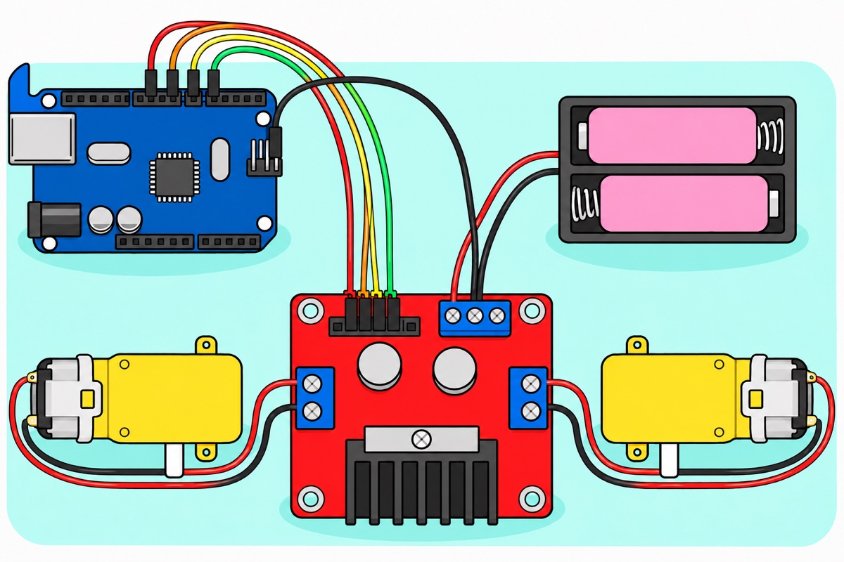
The pre-wired TT motor’s leads end in bare tinned wire and the L298N’s motor and power connections are screw terminals: no breadboard, no soldering, just a small screwdriver. Power is two 18650 cells in the two-slot holder: its spring and flat contacts sit at opposite ends of the two bays, so the cells load head-to-toe, and a metal link at the end away from the wires joins one cell’s − to the other’s +, which puts them in series — 7.4V nominal, 8.4V charged. The 3.7V moulded into the base is the voltage of each cell it holds, not of the pack. That suits the L298N: its transistors drop around 2V (the why is in our L298N speed-control guide), so the motors see about 5.4–6.4V, right at their rating. A 4×AA holder, the type the 2WD kit ships with, is only a fallback: its 6V leaves about 4V at the motors, and too little headroom for the board’s own 5V regulator, which needs roughly 2V above its output, so the driver’s logic supply sags whenever the motors pull.
| L298N point | Connects to | How |
|---|---|---|
| OUT1 + OUT2 (blue 2-way terminal) | Left motor red + black leads | bare ends clamped under the screws |
| OUT3 + OUT4 (opposite edge) | Right motor red + black leads | bare ends clamped under the screws |
| VS / +12V (3-way terminal) | Battery holder red wire | bare end clamped |
| GND (middle of the 3-way terminal) | Battery holder black wire + Uno ground | bare end and one jumper’s male pin, clamped together |
| IN1, IN2, IN3, IN4 (male header pins) | Uno D8, D9, D10, D11 | M-F jumpers: female end on the L298N pin, male end into the Uno socket |
| ENA, ENB | nothing — leave the black jumper caps on | caps on = both channels at full speed |
| 5V-EN jumper | stays fitted | the onboard regulator makes the board’s own 5V logic from VS; leave the +5V terminal empty, because the Uno runs on USB and two 5V sources wired together fight each other |
The ground row matters: the Uno’s IN signals are only “high” relative to its own ground, so both boards must share one. With the M-F jumpers in this list, clamp one jumper’s male pin into the GND terminal beside the battery’s black wire and slide its female end over the GND pin of the Uno’s 2×3 ICSP header — the corner pin diagonally opposite the pin-1 mark; confirm it with a multimeter’s continuity beep to a GND socket before powering up, because the far end of that same row of three is the Uno’s 5V pin. No meter? Use a male-to-male lead (like these) instead and skip the guesswork: pin in the terminal, pin in any GND socket.
The leads are thin: twist each bare end and fold it back on itself so the screw bites, then tug-test every terminal — a lead that slips out looks exactly like a dead motor. Clamp everything with the cells out of the holder and fit them last: these 18650s are unprotected, so if the holder’s bare ends touch while the cells are in, nothing limits the current and the wires get hot enough to burn within seconds. Check red to VS and black to GND first, too — nothing on the L298N blocks a reversed pack, which shorts the cells through its flyback diodes. There is no power switch: lifting one cell out is the off switch.
Power the Uno from USB, upload this with the cells still out, then fit the cells and hold the motors down — a starting motor twists its own body as hard as it turns the shaft. Both shafts run forward three seconds, stop, then reverse:
// First spin: two TT motors through an L298N, direction only.
// ENA and ENB keep their black jumper caps ON = both channels at full speed.
// Speed control (PWM on ENA/ENB) is covered in our L298N guide.

const int IN1 = 8;   // left motor, direction input 1
const int IN2 = 9;   // left motor, direction input 2
const int IN3 = 10;  // right motor, direction input 1
const int IN4 = 11;  // right motor, direction input 2

void setup() {
  pinMode(IN1, OUTPUT);
  pinMode(IN2, OUTPUT);
  pinMode(IN3, OUTPUT);
  pinMode(IN4, OUTPUT);
}

void bothForward() {
  digitalWrite(IN1, HIGH);
  digitalWrite(IN2, LOW);
  digitalWrite(IN3, HIGH);
  digitalWrite(IN4, LOW);
}

void bothReverse() {
  digitalWrite(IN1, LOW);
  digitalWrite(IN2, HIGH);
  digitalWrite(IN3, LOW);
  digitalWrite(IN4, HIGH);
}

void stopMotors() {
  digitalWrite(IN1, LOW);   // both inputs LOW with ENA/ENB held HIGH = motor brakes to a stop
  digitalWrite(IN2, LOW);
  digitalWrite(IN3, LOW);
  digitalWrite(IN4, LOW);
}

void loop() {
  bothForward();
  delay(3000);
  stopMotors();
  delay(1000);
  bothReverse();
  delay(3000);
  stopMotors();
  delay(1000);
}
Because those cells are unprotected flat-tops, charge them only in a proper 18650 charger and store them where the terminals cannot short — our 18650 charging guide covers the habits that keep lithium cells boring.
How do you pair wheels for a small robot car?
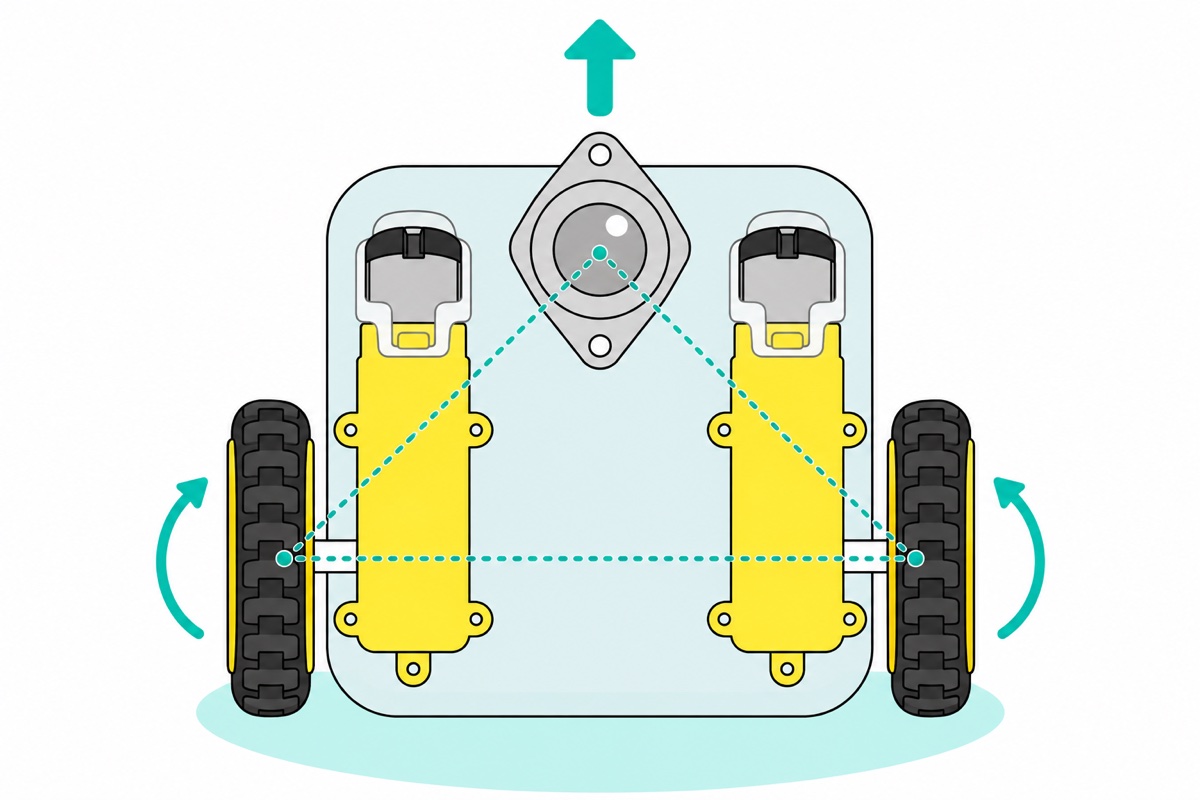
The 68mm yellow wheel’s hub has an elongated socket matching the TT motor’s dual-flat shaft: it pushes straight on and the flats carry the drive — no grub screw, no slipping. Because the shaft protrudes from both sides of the gearbox, two identical motors mount as mirror images, one each side of the chassis, wheels facing out.
Mirrored motors face opposite directions, so identical wiring drives one wheel forward and one back. That is normal, not a fault: whichever wheel runs backwards gets its two leads swapped at the screw terminal — reversed current through the winding reverses its magnetic push against the can’s fixed magnets, so the shaft turns the other way. Swapping that motor’s two pin numbers in the sketch does the same job.
Two wheels on one axle tip like a seesaw, so a third contact point holds the car level: a steel ball caster, whose ball rolls in any direction and so never fights a turn. The car steers by running its two wheels at different speeds — the slower side becomes the inside of the curve. The 2WD chassis kit packages that whole pattern — plate, two TT motors, wheels, a swivel caster, hardware — more cheaply than buying pieces one by one, with one catch: its motors arrive with bare tabs and loose leads, so plan on four solder joints. The full build is our obstacle-avoiding robot car, and the same base drives the line follower.
Which TT motor should you buy?
The TT motor sells in two states, and the difference is your first ten minutes. The TT motor with pre-soldered wires ships with red and black leads already on the brush tabs, ends stripped and tinned — they clamp straight into the L298N’s screw terminals, which is why it anchors this parts list. The bare TT motor and the motor-with-wheel set cost less but arrive with bare brush tabs and no leads — a good buy if you own an iron and can do two joints per motor (technique in our soldering guide), a dead end on day one if you don’t.
Beyond the family: the encoder version adds speed feedback (more in the FAQ), the metal-geared N20 packs a gearbox into a far smaller body, and if you are weighing geared DC against steppers and servos, start at which motor should you use.
Common mistakes we see
Wiring the motor straight to a pin “just to test it”. It may even spin, briefly, while the pin cooks — 150mA free-run against a 40mA absolute maximum, 1.5A at the first stall. Test through the driver, every time.
Feeding the motors from the Uno’s 5V pin. A motor starting from rest has no back-voltage yet, so for an instant it draws close to its stall current, far past the 500mA the Uno’s USB fuse allows. The 5V rail dips, the Uno resets and the motor jerks again, in a loop that looks like a code bug. Motors get their own battery; the two boards share only ground.
Treating one backwards wheel as a broken motor. Mirror-mounted motors are supposed to disagree; the fix is swapping that motor’s two leads at its OUT terminal.
Expecting 200 RPM on the road. The rating is no-load at a full 6V. Under load, from a sagging battery, through the driver’s ~2V drop, a real car cruises well below the 0.7 m/s ceiling — physics, not a fault.
Loading the 18650s nose-to-nose. The two-slot holder is a series holder: cells go head-to-toe, negative ends on the springs. Both cells facing the same way puts one in backwards, and a reversed cell subtracts instead of adding: the two cells cancel, and the pack reads close to 0V instead of about 8V. Follow the + and − moulded into each bay, and if you own a meter, the holder’s wires should read 7.4–8.4V before they go near the board.
FAQ
What does 1:48 mean on a TT motor?
Forty-eight turns of the internal motor make one turn of the output shaft: the gear train divides speed by 48 and multiplies torque many times over (by less than 48, since friction in the plastic gears takes a share), turning a 9,600 RPM toy-grade can into a shaft that turns about 200 RPM with no load.
Can I run a TT motor directly from an Arduino?
No. The motor’s 150mA free-run and roughly 1.5A stall are far beyond the 40mA absolute maximum of an ATmega328P pin, and the coil kicks a voltage spike into the pin at switch-off. Any motor driver fixes it — the L298N here, or smaller boards for lighter builds.
How fast does a robot car with TT motors go?
At 6V the motor turns up to 200 RPM unloaded, and a 68mm wheel covers about 0.21 m per turn, so the ceiling is about 0.7 m/s (2.5 km/h) — roughly half a normal walking pace. A real car runs slower: load, battery sag and the driver’s ~2V drop all take a share.
Can a TT motor run on a 9V battery?
Keep the motor itself at 3–6V. Two 18650s through an L298N work out right because the driver drops about 2V. The rectangular 9V PP3 is the wrong tool twice over: too much voltage for the motor, and too little current capability — it sags flat the moment a motor loads up.
Do I need the TT motor with an encoder?
Not for a first robot. The encoder version adds a small sensor board at the motor’s rear that reports how fast it is actually turning, which matters when a car must drive dead straight or measure distance — two plain TT motors never spin exactly alike. Move to encoders when you find yourself trimming motor speeds by eye.
Last updated November 2026. Stuck? Chat with us on WhatsApp.
