

Tutorials
Arduino Obstacle-Avoiding Robot Car: 2WD Build with Full Code
Aug
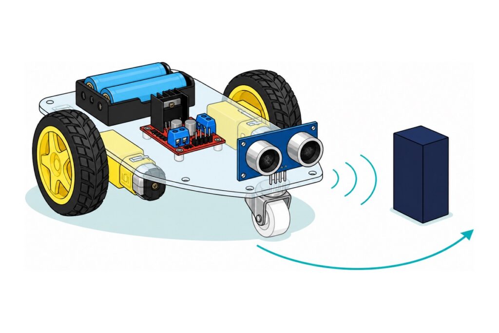
An obstacle-avoiding robot car is a 2WD chassis, an L298N driver, an HC-SR04 pointed forward, and one loop that measures, decides, then drives. The mechanics are an afternoon of screws; what decides whether your car rolls or crawls is the battery, because the L298N quietly swallows around two volts before the motors ever see it.
What parts does an obstacle-avoiding robot car need?
The 2WD chassis kit supplies the mechanics — acrylic plate, two TT gear motors, wheels, a front caster, screws and a rocker switch. Every electrical part is yours to add, and the AA holder the kit does include is the one item this guide replaces.
Parts list — obstacle-avoiding 2WD robot car
 2WD 4WD Smart Car Chassis Single Layer Acrylic Arduino Smart Car Chassis Kit With Motor - 2WD CAR KIT
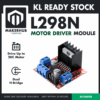 L298N Motor Driver Module Arduino Compatible Dual H Bridge Dual DC Motor Control Arduino Robotic Car
 Ultrasonic Sensor HC-SR04 Ultrasonic Range Detection Distance Finder Obstacle avoidance For Arduino Application
 Arduino Compatible UNO R3 FT232 Development Board Arduino Compatible CH340 Alternative
 Data Cable Type-A Type-C MicroUSB Type-B 0.5m 1m 30cm 0.3m 100cm Data Transfer Upload Code - TYPE-A TO TYPE-B (1.0M)
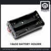 18650 Battery Holder 1/2/3/4 Slot 3.7V Battery Cell Housing Battery Case Battery Casing - 18650 BATTERY HOLDER (2)
 3.7V 18650 Battery Rechargeable Li-Ion Battery 1200mAh 2200mAh 3200mAh Flat Top - 18650 Li-Ion Battery (2200mAh)
 40pcs Dupont Wire 10cm 20cm 30cm for Breadboard DIY Experiment Jumper Wire Breadboard wire - DUPONT WIRE M-F 20CM
 40pcs Dupont Wire 10cm 20cm 30cm for Breadboard DIY Experiment Jumper Wire Breadboard wire - DUPONT WIRE M-M 20CM
Parts list
 TP4056 18650 Battery Charger Module Lithium Ion Battery Li-ion Battery Charger Type C Micro USB - TP4056 CHARGER (TYPEC)
 Soldering Service for Circuit Boards & Electronics - 5 Pins Soldering Service
 Electrical Insulation Tape 18mm x 10m PVC Color Coded Marking Red White Blue Yellow Green Black - ELECTRICAL TAPE (BLACK)
The 4WD chassis is the alternative lane and runs this exact sketch. The TP4056 recharges the two 18650 cells between runs, the 5-pin soldering service covers the four motor-tab joints if you would rather not solder them yourself, and the tape straps the sensor to the chassis nose and insulates the battery joins.
Wire gender is what a first order usually gets wrong. The L298N control header and the HC-SR04 header are both male pins while the Uno‘s edges are female sockets, so all ten signal wires are male-to-female. The two power runs are the exception: one end is a bare pin clamped under a screw in the L298N’s terminal block and the other has to enter a female socket on the Uno, so both ends must be male — a male-to-female wire arrives at the Uno carrying a socket, and two sockets do not mate. Those two come from the male-to-male pack. Rigid breadboard jumper wire suits neither job here. The Uno programs over full-size USB-B, so it needs the A-to-B cable.
How do you assemble the chassis before any wiring?
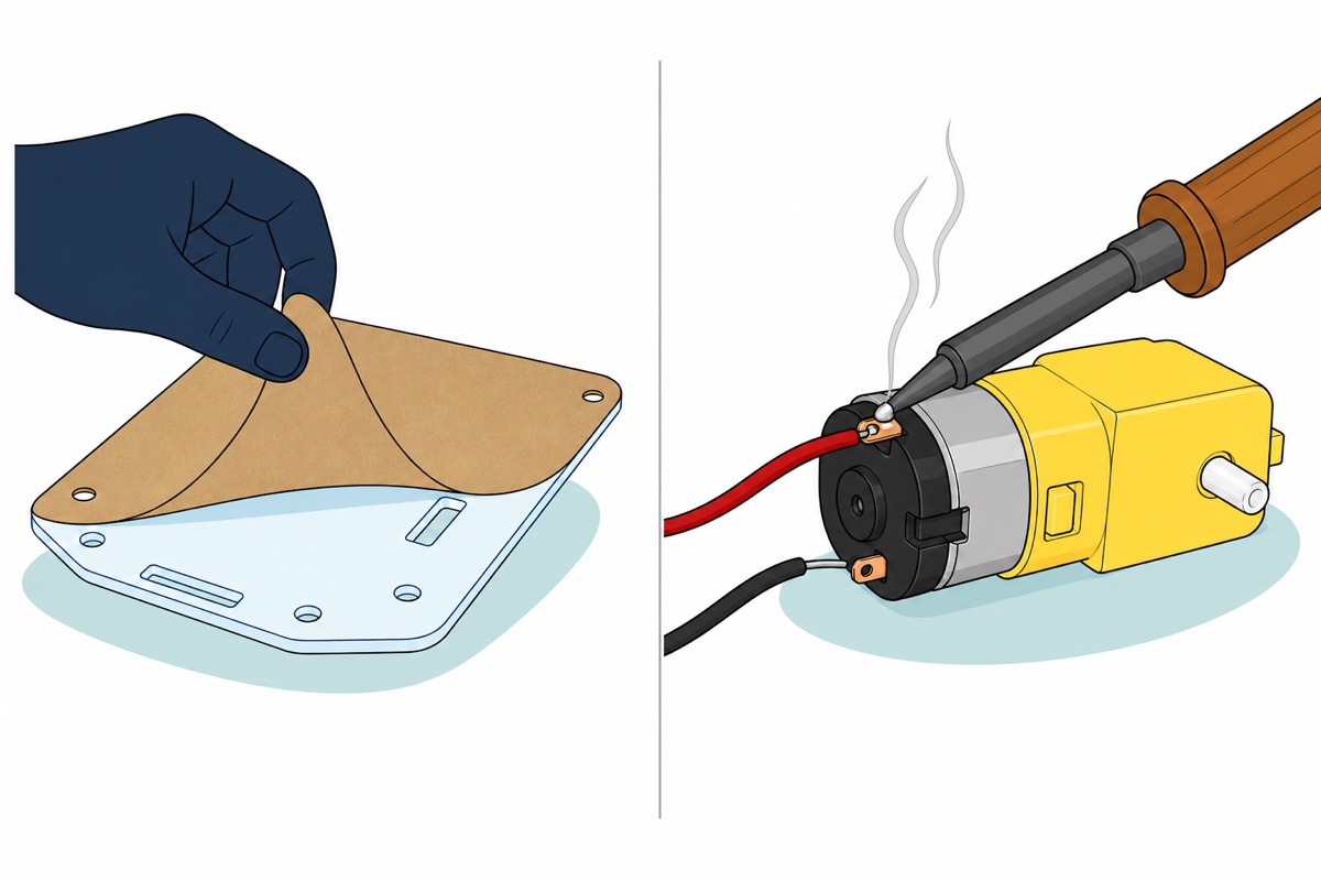
The 2WD chassis plate ships with kraft-paper protective film on both faces, so the “cardboard” you unpack is not the chassis. Peel it off both sides, and off the small T-shaped motor mounting tabs, and every hole and slot in the clear acrylic becomes visible.
Soldering is not optional here. The TT motors arrive with bare metal tabs on the rear end cap and the loose red and black wire pairs with bare tinned tips: four joints, two per motor. Our soldering guide covers the technique, and the 5-pin soldering service covers exactly these four joints if you would rather post the parts to us. Keep the iron brief — the tabs sit millimetres from the plastic end cap. The kit’s rocker switch has bare lugs too, so fitting it in the pack’s positive lead is two more joints; leave the switch out and you power the car down by lifting one cell out of the holder. The L298N side needs no solder at all — every wire there clamps under a screw.
The rest is mechanical — motors between the acrylic tabs, wheels onto the white cross-shaped shafts, caster under the front edge — and worth watching once before you start:
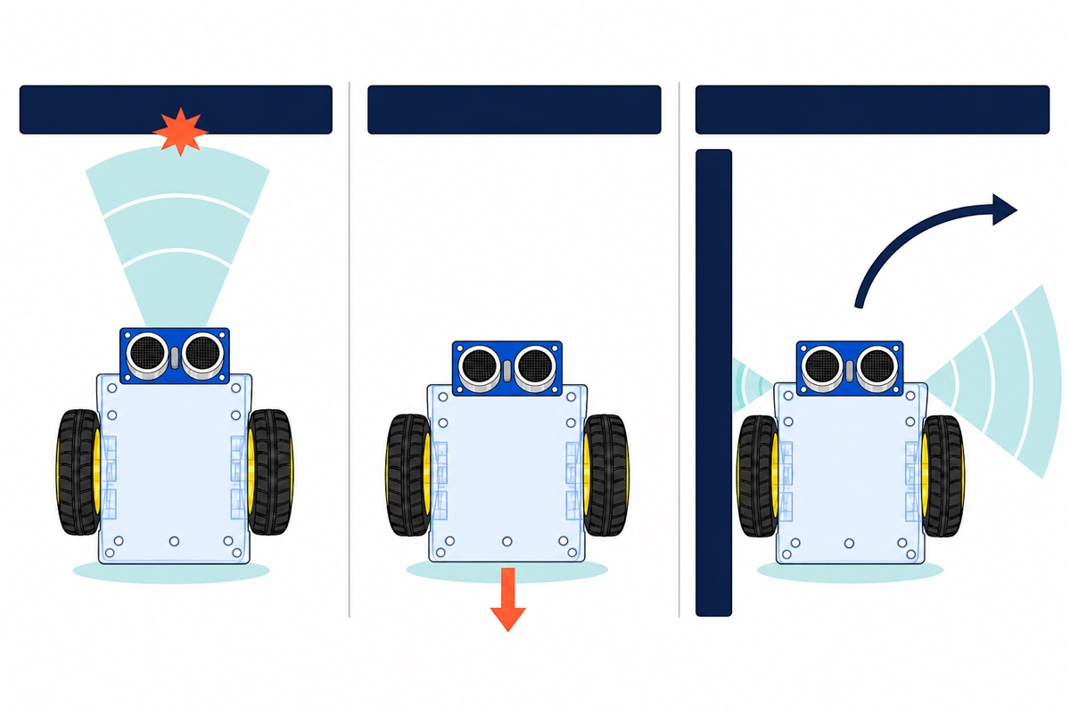
Nothing in the kit holds the HC-SR04, so plan its place before the deck fills up. The sensor belongs at the very front, level and facing straight ahead, with both transducers clear of the acrylic edge — set back behind the nose, it hears the deck instead of the room. Level matters more than it looks: the burst leaves in a cone roughly 15 degrees wide, so a sensor tilted slightly down finds the floor a couple of tens of centimetres ahead and calls it a wall that never goes away. Two cable ties through the chassis slots, or a strip of insulation tape round the plate edge, hold it well enough; the Uno and the L298N go behind it on the brass standoffs, with every header left reachable.
Why does the battery choice decide whether the car moves?
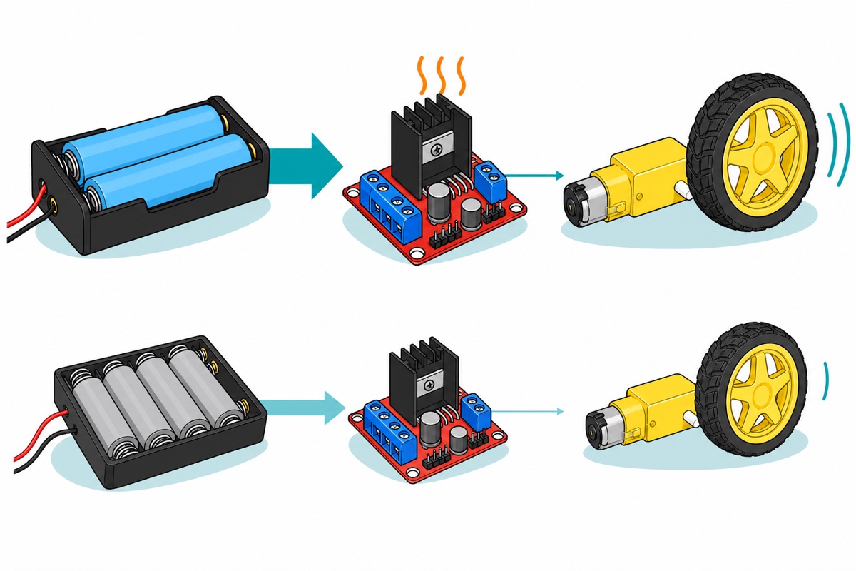
The L298N is an old bipolar darlington bridge, not a MOSFET one. Motor current passes through a conducting transistor stack on the high side and another on the low side, and a bipolar transistor in saturation still holds a stubborn voltage across itself instead of acting like a closed switch. ST’s L298 datasheet lists the two together as a total drop of 1.8 V minimum and 3.2 V maximum at 1 A, and its Figure 1 plots that drop climbing with current — so the sums below, which use the 1.8 V floor, are the kind case. It is a share that never reaches the motor and becomes heat in the black heatsink.
Now the kit’s own holder. Four fresh AA cells make 6 V; subtract the bridge and the motors see about 4.2 V, and alkaline internal resistance pulls it lower the moment both motors start together. A TT motor is rated 3–6 V at a continuous no-load current of 150 mA ±10%, several times that when a wheel is held — so 4.2 V sagging under load crawls on tile and stops on a rug. Six volts also cannot run the Uno through VIN, which wants 7–12 V.
Two 18650 cells in the 2-slot holder sit head to tail, which is series: 7.4 V nominal, 8.4 V fully charged. Subtract the bridge and the motors see about 5.6 V at nominal, squarely inside their band, while the sketch’s forward PWM of 200 out of 255 keeps a freshly charged pack near 5.2 V average. That 7.4 V also clears the dropout of the L298N’s own 5 V regulator, whose +5V screw terminal powers the Uno — board plus sensor is well under a tenth of an amp.
Leave the small 5V-EN jumper fitted: it connects that regulator to the +12V input, and comes off only above roughly 12 V in. And do not substitute a 4-slot 18650 holder, which belongs on higher-voltage builds — multi-slot holders series their cells too, so four is 14.8–16.8 V, far beyond what a 3–6 V motor survives even after the bridge’s share.
How do you wire the L298N, the sensor and the Uno?
The L298N ships with two black jumper caps on ENA and ENB, tying both enables permanently high — full speed, no speed control. Pull them off and put the exposed pins on Arduino PWM outputs; that is what lets the sketch’s trim constants do anything. Our L298N speed control guide takes it further.
| From | To | Why |
|---|---|---|
| Battery holder red lead, through the kit’s rocker switch | L298N +12V screw terminal | The 7.4 V pack feeds both the bridge and the onboard 5 V regulator |
| Battery holder black lead | L298N GND (middle screw) | Return path for the motor current |
| L298N +5V screw terminal | Uno 5V pin | Regulated 5 V from the module runs the Uno and the sensor — no second battery |
| L298N GND | Uno GND | Without a shared ground the IN pins have no reference and the car behaves randomly |
| L298N OUT1 / OUT2 | Left motor’s two wires | Swap them if that wheel spins backwards — no code change needed |
| L298N OUT3 / OUT4 | Right motor’s two wires | Same rule for the other side |
| L298N IN1 / IN2 | Uno D9 / D8 | One HIGH and one LOW picks the left motor’s direction |
| L298N IN3 / IN4 | Uno D7 / D6 | Same pair for the right motor |
| L298N ENA / ENB (caps removed) | Uno D10 / D11 | PWM speed for each side, which is where the per-motor trim lives |
| HC-SR04 Vcc | L298N +5V screw terminal, alongside the Uno’s feed | The Uno has a single 5V pin and the module’s wire is already in it; the screw terminal holds both. The sensor draws about 15 mA |
| HC-SR04 Gnd | Uno GND (the board has three) | A second Uno ground pin, so the sensor shares the Arduino’s reference |
| HC-SR04 Trig_RX_SCL | Uno D3 | The 10 µs pulse that fires the burst |
| HC-SR04 Echo_TX_SDA | Uno D2 | Stays high for the flight time of the sound |
Two 18650 cells in series carry no fuse between them and whatever they touch: a healthy 2200 mAh cell pours tens of amps into a dead short, hot enough to melt insulation and burn a finger. Strip each holder lead only as far as the screw terminal needs, tighten onto bare copper rather than onto insulation, and tape every exposed join before the pack goes down among the chassis screws. Seat each cell to the polarity moulded into its slot — the spring contact is always the negative end — and pair two cells of the same type and charge state, so the stronger is not left driving the weaker.
How does the HC-SR04 turn an echo into centimetres?
The HC-SR04 fires an eight-cycle 40 kHz burst from its “T” transducer when Trig is held high for 10 µs, listens on “R”, then holds Echo high for exactly as long as that sound was in flight. Sound travels about 343 m/s in room-temperature air — 0.0343 cm per microsecond — and the trip is out and back, so centimetres are microseconds ÷ 58. Our sensor guide takes that part alone.
The revision we ship carries multi-mode silkscreen: Vcc / Trig_RX_SCL / Echo_TX_SDA / Gnd. If you are hunting for a pin marked plainly “Trig”, it is Trig_RX_SCL — the extra names are alternate modes this build ignores.
Now the trap that strands cars in empty rooms. Arduino’s pulseIn() gives up after its timeout and returns 0, not an error — the AVR core’s wiring_pulse.c returns zero rather than a duration when no pulse was measured. Divide zero by 58 and you get 0 cm, which a naive sketch reads as a wall against the sensor, so the car brakes for nothing. Angled walls, soft furnishings and open floor all scatter the burst away. Treat zero as maximum range instead: no echo means nothing is in front.
What is the complete source code for the obstacle-avoiding robot car?
The HC-SR04 and the L298N both need no library. Select Arduino Uno, upload over the A-to-B cable, and open the Serial Monitor at 9600 baud to watch the readings while you hold the car. It compiles to 3,194 bytes, about 9% of the Uno’s flash. Upload with the pack switched off, then unplug USB before switching it on. The two supplies must never be live together: the L298N’s +5V arrives on the Uno’s 5V pin, past both the board’s own regulator and the fuse guarding its USB port, so nothing stands in front of that rail — join it to a laptop’s 5 V as well and whichever reads higher pushes current into the other. Rest the car on a book for its first run, wheels hanging free, so a wrong pin number costs a spinning wheel and not a fall off the table.
// Obstacle-avoiding 2WD robot car: Arduino Uno + L298N + HC-SR04.
// No library needed. Trig and Echo are plain digital pins, and each motor
// takes two direction pins plus one PWM enable pin on the L298N.

// ---- Pins ----
const uint8_t TRIG_PIN = 3;   // HC-SR04 Trig_RX_SCL
const uint8_t ECHO_PIN = 2;   // HC-SR04 Echo_TX_SDA

const uint8_t ENA_PIN = 10;   // left motor speed     (PWM)
const uint8_t IN1_PIN = 9;    // left motor direction
const uint8_t IN2_PIN = 8;
const uint8_t IN3_PIN = 7;    // right motor direction
const uint8_t IN4_PIN = 6;
const uint8_t ENB_PIN = 11;   // right motor speed    (PWM)

// ---- The two numbers you tune ----
// No two TT motors are identical. Run the car straight on a flat floor and
// drop the side that pulls ahead, 5 counts at a time, until it tracks true.
const uint8_t SPEED_LEFT  = 200;
const uint8_t SPEED_RIGHT = 200;
const uint8_t SPEED_TURN  = 220;  // a pivot fights both tyres, so it needs more

// ---- Decisions ----
const uint16_t CLEAR_CM  = 25;    // closer than this and the car reacts
const uint16_t NO_ECHO_CM = 400;  // what a timed-out ping counts as: open floor

const unsigned long REVERSE_MS = 400;
const unsigned long PIVOT_MS   = 350;
const unsigned long ECHO_TIMEOUT_US = 25000UL;  // ~4.3 m round trip, then give up

// One ping. Returns centimetres, or NO_ECHO_CM when nothing came back.
uint16_t pingOnceCm() {
  digitalWrite(TRIG_PIN, LOW);
  delayMicroseconds(2);
  digitalWrite(TRIG_PIN, HIGH);
  delayMicroseconds(10);        // the datasheet's 10 us trigger pulse
  digitalWrite(TRIG_PIN, LOW);

  unsigned long echoUs = pulseIn(ECHO_PIN, HIGH, ECHO_TIMEOUT_US);

  // pulseIn returns 0 when it times out. Zero is NOT zero centimetres:
  // nothing echoed, so the path ahead is open, not a wall against the sensor.
  if (echoUs == 0) {
    return NO_ECHO_CM;
  }

  // Sound covers 1 cm out and 1 cm back in about 58 us at room temperature.
  return (uint16_t)(echoUs / 58);
}

// Median of three pings: one freak reflection can no longer steer the car.
uint16_t distanceCm() {
  uint16_t a = pingOnceCm();
  delay(30);
  uint16_t b = pingOnceCm();
  delay(30);
  uint16_t c = pingOnceCm();

  uint16_t swap;
  if (a > b) { swap = a; a = b; b = swap; }
  if (b > c) { swap = b; b = c; c = swap; }
  if (a > b) { swap = a; a = b; b = swap; }
  return b;
}

void driveLeft(bool forward, uint8_t speed) {
  digitalWrite(IN1_PIN, forward ? HIGH : LOW);
  digitalWrite(IN2_PIN, forward ? LOW : HIGH);
  analogWrite(ENA_PIN, speed);
}

void driveRight(bool forward, uint8_t speed) {
  digitalWrite(IN3_PIN, forward ? HIGH : LOW);
  digitalWrite(IN4_PIN, forward ? LOW : HIGH);
  analogWrite(ENB_PIN, speed);
}

void stopBoth() {
  analogWrite(ENA_PIN, 0);
  analogWrite(ENB_PIN, 0);
}

void goForward()  { driveLeft(true,  SPEED_LEFT);  driveRight(true,  SPEED_RIGHT); }
void goBackward() { driveLeft(false, SPEED_LEFT);  driveRight(false, SPEED_RIGHT); }
void pivotLeft()  { driveLeft(false, SPEED_TURN);  driveRight(true,  SPEED_TURN);  }
void pivotRight() { driveLeft(true,  SPEED_TURN);  driveRight(false, SPEED_TURN);  }

void setup() {
  Serial.begin(9600);

  pinMode(TRIG_PIN, OUTPUT);
  pinMode(ECHO_PIN, INPUT);

  pinMode(ENA_PIN, OUTPUT);
  pinMode(IN1_PIN, OUTPUT);
  pinMode(IN2_PIN, OUTPUT);
  pinMode(IN3_PIN, OUTPUT);
  pinMode(IN4_PIN, OUTPUT);
  pinMode(ENB_PIN, OUTPUT);

  stopBoth();
  Serial.println(F("Obstacle car ready - put it down."));
  delay(2000);   // time to set the car on the floor and let go
}

void loop() {
  uint16_t cm = distanceCm();
  Serial.println(cm);

  if (cm > CLEAR_CM) {
    goForward();
    delay(40);
    return;
  }

  // Something is close. Stop before reversing: throwing a loaded gearbox
  // straight from forward into reverse is the hardest thing you can ask
  // of both the plastic gears and the H-bridge.
  stopBoth();
  delay(200);

  goBackward();
  delay(REVERSE_MS);
  stopBoth();
  delay(150);

  // Look both ways. With no servo the car must turn its own body to aim
  // the sensor, so measure after each pivot and commit to the roomier side.
  pivotLeft();
  delay(PIVOT_MS);
  stopBoth();
  delay(150);
  uint16_t leftCm = distanceCm();

  pivotRight();
  delay(PIVOT_MS * 2);
  stopBoth();
  delay(150);
  uint16_t rightCm = distanceCm();

  if (leftCm > rightCm) {
    pivotLeft();                // swing back past centre to the left-hand view
    delay(PIVOT_MS * 2);
    stopBoth();
  }

  delay(100);   // settle, then the next loop drives into the gap it chose
}
CLEAR_CM is 25 rather than 5 because the car keeps moving while it thinks. analogWrite() hands its PWM to a hardware timer, so the motors run on right through distanceCm(), and three pings with their settling delays cost roughly a tenth of a second — longer again when one has to time out. The car covers several centimetres in that window and a few more after it, because stopBoth() takes the enable pins low, which releases the bridge and lets the wheels free-wheel rather than braking them. The near end matters too: the HC-SR04 cannot measure closer than about 2 cm, and an obstacle inside that blind spot gives no usable echo — which this sketch, by design, reads as open floor. Reacting at 25 cm keeps the wall in the range where the sensor is honest.
Why does it curve instead of driving straight?
Two TT motors are never identical: the moulded gear trains have different friction and the brushes bed in differently, so one side turns faster at the same PWM value. That is why SPEED_LEFT and SPEED_RIGHT are separate constants. Set it on a flat floor and watch which way it drifts: a car veers away from its faster side, so one curving left has the quicker right-hand motor. Lower that side’s constant by five counts, re-upload, and repeat until it holds a line over a couple of metres.
Keep both numbers fairly high. Below roughly 100 the average voltage after the bridge’s drop no longer overcomes the gearbox’s stiction, so the wheel buzzes without turning — a low PWM value is not a slow motor, it is a stalled one.
The routine’s shape matters as much as its numbers: looking both ways before turning is what defeats the corner trap, where a car that always turns the same way ping-pongs between two walls. The line follower on this chassis solves the opposite problem.
What can you add once it drives?
The SG90 servo is the obvious upgrade: carried on its shaft, the HC-SR04 looks left and right by itself without pivoting the car’s body — faster, and far less likely to clip a table leg mid-turn; in code it swaps the two pivots for two servo positions and keeps the same comparison, the technique shown in our smart dustbin build. Expect to improvise the mount, as these servos ship bare without horns or screws — a scrap of acrylic and insulation tape does it.
The 4WD chassis runs this sketch unchanged: wire each side’s two motors in parallel into one L298N channel, which a driving pair loads to a fraction of that channel’s 2 A rating and which gains grip on carpet. Stalling is the exception — one jammed TT motor pulls about 1.5 A, so a wedged pair is over the channel’s rating; free the car rather than let it push. It is a different kit though — no caster, switch or AA holder. A TP4056 charger then finishes the build; read our 18650 charging guide first.
Common mistakes we see from real customers
Everything is wired and nothing moves. Check the ENA and ENB caps first, then the ground: caps removed with the enable pins undriven leaves both channels disabled, and an L298N GND that never reaches the Uno’s leaves the IN pins floating against a battery negative the Arduino cannot see.
One wheel spins the wrong way. Nothing is broken — a DC motor’s direction is only which of its two wires is positive. Swap that motor’s pair at OUT1/OUT2 or OUT3/OUT4 and leave the code alone.
It ran on USB and dies on batteries. Usually flat cells, cells seated backwards, or a pack wired into the Uno instead of the L298N’s +12V terminal — measure the pack first.
It resets itself whenever it turns. A pivot is the heaviest current the car ever draws, and the Uno lives off the L298N’s small 5 V regulator, which needs roughly two volts more at its input than it hands out. A charged 7.4 V pack has that headroom several times over; tired, part-charged or salvaged cells with high internal resistance do not, and the kit’s 6 V AA pack starts below what the regulator wants before it even sags. The symptom is unmistakable: the car freezes for two seconds and starts its routine again, because that is delay(2000) in setup() running a second time.
The readings jump around once the motors run. Brush arcing inside a DC motor is a small radio transmitter with wires attached, so twist each motor’s pair together and route them away from the sensor’s four. A 0.1 µF ceramic capacitor soldered across each motor’s two terminals is the standard cure on these kits.
FAQ
Why does the car stop when nothing is in front of it?
A timed-out ping returns 0 from pulseIn(), and unchecked code turns that into 0 cm. Treat zero as maximum range.
What battery should I use for a robot car with an L298N?
Two 18650 cells in series, not a 9 V block: a smoke-alarm battery’s internal resistance is far too high, so two motors starting together collapse its voltage and reset the Arduino.
Why does the sensor miss walls it should see?
An ultrasonic burst reflects like light off a mirror, so an angled surface sends the sound sideways instead of back, and curtains or sofas absorb it. Aim it level and forward.
Can I use an ESP32 instead of the Uno?
Yes, with one caution: Echo swings to 5 V while ESP32 pins are 3.3 V, so that line needs a two-resistor divider. IN and EN take 3.3 V logic unchanged.
Last updated August 2026. Stuck? Chat with us on WhatsApp.
