

Tutorials
CNC Shield V3 + Arduino Uno: A4988 Setup, GRBL 1.1 and Your First Stepper Test
Nov
To get a CNC Shield V3 running on an Arduino Uno: set the microstep jumpers, seat each A4988 with its EN pin on the socket’s EN corner, set the current limit with a multimeter before any motor is connected, feed the blue terminal 12–24V DC, flash GRBL 1.1 and jog over serial. Do them in that order and the first motor test is uneventful; skip the orientation check or the current limit, and the usual price is a dead driver.
What is in the CNC Shield V3 kit, and how does it stack?
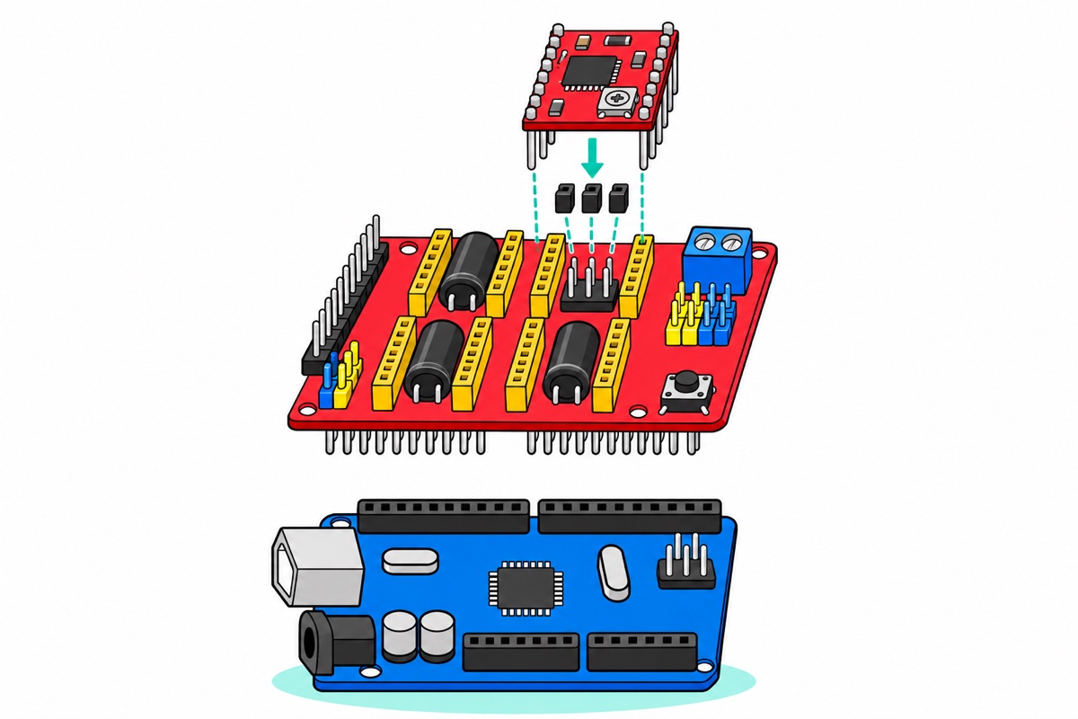
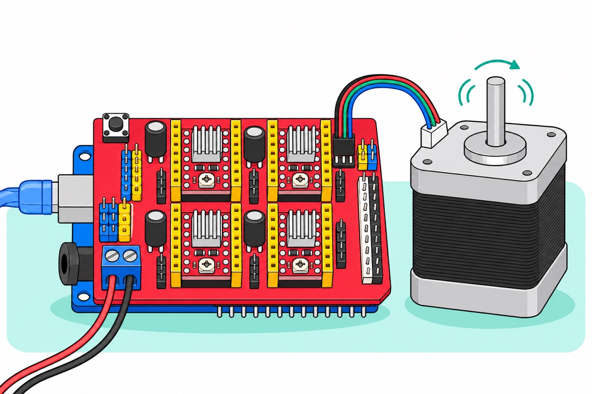
The CNC Shield V3 kit arrives as separate parts: the red shield itself (the Protoneer 3.00 design), a blue Uno R3-compatible board, four A4988 drivers with their header pins already soldered, four stick-on heatsinks, a USB cable and a spare header strip. There is no soldering anywhere in this build — everything plugs together. Not in the box: a power supply and the motors, both covered below.
Put a strip of electrical tape over the top of the Uno’s metal USB socket first: the shield’s underside solder joints sit on or just above it and can short against it. The shield’s long male pins only line up one way with the Uno’s irregular headers — with the blue power terminal over the Uno’s DC jack. Push it down evenly until fully seated, with no pin hanging past the end of a header. From here the order matters: jumpers go on before the drivers, because they sit underneath them.
Parts list: CNC Shield V3 starter build
 CNC SHIELD V3 KIT WITH 4X A4988 DRIVERS & UNO R3 BOARD 4-AXIS STEPPER MOTOR CONTROLLER
 Power Supply Adapter DC Universal AC to DC Converter PSU 5V2A 5V3A 9V2A 12V2A - P.S. ADAPTOR (12V2A)
 5.5x2.1mm DC Power Male Connector Plug Jack Adapter for Arduino DIY Electronics Projects - 5.5x2.1 DC CONNECTOR (F)
 XL830L Digital Multimeter with backlight Portable Multimeter Electronics Project
Optional: spare driver
| Item | Price | Qty | |
|---|---|---|---|
 A4988 STEPPER MOTOR DRIVER 35V 2A MICROSTEPPING MODULE FOR CNC 3D PRINTER ARDUINOA4988MD | RM9.90 |
Which way do the A4988 drivers face — and what do the microstep jumpers do?
The A4988 socket is symmetrical, so the driver physically fits both ways — but only one way survives. Each driver’s pin names are printed along its edges: match the driver’s EN corner to the EN marking on the shield’s socket; the silver trimpot then sits at the STEP/DIR end. Cross-check: the driver’s B2, A2, A1 and B1 pins face that axis’s 4-pin motor header, which is wired straight to them. Inserted backwards, the shield’s 12V motor pin meets the driver’s DIR input, a logic pin rated for 5.5V at most, and the chip dies the moment power arrives. Check all four, then press the finned heatsinks onto the black chips.
Before the drivers go in, set microstepping. Under each socket sit three jumper positions (MS1, MS2, MS3) that pull the driver’s mode pins high. A typical NEMA 17 has 200 full steps per revolution; microstepping has the driver feed the two coils intermediate current levels so the shaft settles between full steps — 3,200 positions per revolution at 1/16, which is why a microstepped motor runs smoother and quieter than the raw 1.8° clunk. Fit all three jumpers under every axis you use: 1/16 is the usual GRBL starting point because the smoothness costs no usable speed — GRBL’s 30,000 step pulses a second still allow about 560 RPM at 3,200 pulses per revolution.
| Jumpers fitted | Microstep mode | Positions per revolution |
|---|---|---|
| None | Full step | 200 |
| MS1 | Half step | 400 |
| MS2 | Quarter step | 800 |
| MS1 + MS2 | Eighth step | 1,600 |
| MS1 + MS2 + MS3 | Sixteenth step | 3,200 |
How do you set the A4988 current limit with a multimeter?
The A4988 is a chopper driver: it switches the full 12V across a motor coil, watches the current climb through a small sense resistor, and cuts the switch the instant that current hits a set ceiling — then repeats, thousands of times a second. That is why a 12V or 24V supply safely drives a motor whose coils are rated around 2–3V: the driver regulates current, and the ceiling is set by the trimpot voltage, Vref. Too high cooks the motor and overheats the driver; too low and the motor stalls or skips steps under load. The trimpot leaves the factory at a random position, so setting it is not optional.
The ceiling is Vref ÷ (8 × R), where R is the sense resistance — the relationship Pololu documents for the A4988 carrier. Our A4988 boards carry two sense resistors marked R100 (0.1Ω) beside the chip, so Vref = 0.8 × the coil current you want. Read your own board before calculating: clones with R050 (0.05Ω) resistors use 0.4 instead, so a Vref copied from an R100 guide would double the current.
Worked example: a typical 42×40mm NEMA 17 of the class Smith3D sells is rated around 1.5A per coil — check the label on your motor’s body. Full rating would need Vref = 0.8 × 1.5 = 1.2V; start conservative at 0.8A instead: Vref = 0.64V. The limit is heat: the driver’s losses grow with the square of the current, and Pololu rates its A4988 carrier at about 1A per coil without a heat sink or fan. You can raise a current limit later; you cannot un-cook a driver.
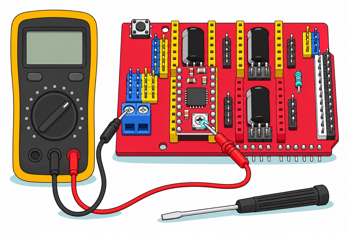
Measure with the motor not connected and only USB plugged in — the trimpot divides the 5V logic supply, so the 12V adds nothing but the risk of a slipped probe bridging it onto a logic pin. Set the multimeter to the 2V DC range, hold the black probe on a GND point such as the − power-terminal screw, and touch the red probe to the metal screw of the trimpot — the screw itself is the Vref point. Turn it in small steps with any small screwdriver to your target, then repeat per driver. This video from Pololu, who designed the original A4988 carrier board, shows the probe-and-turn motion. It runs about nine minutes and is filmed on their DRV8825 board, whose current formula differs — take the technique from the video and the numbers from above, because even Pololu’s own A4988 carriers use 0.068Ω sense resistors, not the R100s on ours:
How do you power the CNC Shield V3 — and why 12–24V, not 36V?
The shield’s blue screw terminal is printed 12–36V, with − and + marked beneath the two screws, and it feeds the motors only — the Uno still runs from USB. So never plug the adapter into the Uno’s own barrel jack, even though it fits: that powers only the Uno and leaves the motor rail dead.
The 36V figure is there for the DRV8825, a 45V-rated driver that fits the same sockets; with A4988s, treat the real ceiling as 24V: the A4988’s absolute maximum motor voltage is 35V, and switching motor coils generates voltage spikes that ride on top of the supply rail. A spike on top of 36V is exactly how drivers die “for no reason”. More voltage buys only speed: current reaches the ceiling faster on each step, so torque holds up at higher step rates — for a first test, 12V is plenty.
The clean no-cutting path: the 12V 2A adapter ends in a 5.5×2.1mm barrel plug, which pushes into the female jack pigtail, whose red and black wire ends screw into the terminal — red to +, black to −. Bench-check first: multimeter on 20V DC, confirm roughly 12V across the pigtail’s bare ends with red on the red wire — a minus sign on the display means the wires are swapped. One measurement catches a mislabelled adapter and reversed polarity, and the shield has no reverse-polarity protection to forgive either.
12V 2A honestly covers one motor at a 0.6–0.8A limit — the chopper behaves like a step-down converter, so supply-side draw sits well below coil current. Running three or four motors hard needs a mains-wired frame PSU with exposed 230V terminals: not a beginner upgrade, and not this article. Barrel sizes and supply ratings have their own guide: how to choose a DC power supply.
How do you flash GRBL 1.1 to the Arduino Uno?
GRBL is the firmware that turns the Uno into a G-code motion controller. Flash it yourself: pin behaviour changed between GRBL versions, so knowing exactly what the board runs matters. Download the ZIP of GRBL 1.1 from the official gnea GitHub releases and unzip it.
In Arduino IDE 2, copy the grbl folder from inside the download into your sketchbook’s libraries folder (usually Documents/Arduino/libraries) and restart the IDE, as GRBL’s own wiki instructs — IDE 2’s Add .ZIP Library menu takes only a ZIP, and GRBL’s ZIP holds the library one folder too deep. In IDE 1.8, Sketch → Include Library → Add .ZIP Library accepts that inner folder directly. Either way, picking the whole download instead of the inner grbl folder is the classic trip-up.
Open File → Examples → grbl → grblUpload, pick Arduino Uno and your port, and upload. No port listed? The kit’s Uno uses a CH340 USB chip that may need a driver; our Arduino Nano setup guide covers it, as the Nano uses the same chip. The firmware fills about 92% of the Uno’s flash and most of its RAM, so the IDE’s Low memory available warning is expected — GRBL sizes its planner buffer to use the Uno’s RAM on purpose.
Open the Serial Monitor at 115200 baud with the line ending set to New Line, because GRBL ignores a command until its line ends. The greeting Grbl 1.1h ['$' for help] is your proof of version.
Now the pin-map catch. The shield’s silkscreen was drawn in the GRBL 0.8 era; from GRBL 0.9 onward, two functions swapped pins so spindle speed PWM could use D11, a hardware-PWM pin. On GRBL 1.1 the labels lie in exactly two places:
| Shield label | Uno pin | What GRBL 1.1 actually does there |
|---|---|---|
| EN / GND | D8 | Enable/disable all drivers (as labelled) |
| X.STEP / X.DIR | D2 / D5 | X axis step and direction (Y: D3/D6, Z: D4/D7) |
| X+ X− / Y+ Y− | D9 / D10 | X and Y limit switches (as labelled) |
| Z+ Z− | D11 | Spindle speed PWM — not the Z limit |
| SpnEn | D12 | Z limit switch — not spindle enable |
| SpnDir | D13 | Spindle direction (as labelled) |
| Abort / Hold / Resume | A0 / A1 / A2 | Reset, feed hold, cycle start (as labelled) |
| CoolEn | A3 | Coolant on/off (as labelled) |
The board simply predates the firmware — GRBL’s own pin map documents the swap. None of this blocks today’s first test: GRBL 1.1 ships with homing and hard limits disabled, so no switches are needed yet.
How do you wire a stepper motor and run the first test?
The kit contains no motor, and the right partner is a NEMA 17 bipolar stepper — four wires, two coils — plugged onto the 4-pin male header beside each driver. Our sister store Smith3D stocks two with 1m cables fitted: the 42×40mm NEMA 17 and the longer 42×48mm NEMA 17. The small 28BYJ-48 from our ULN2003 kits will not work here — it is a 5-wire unipolar motor whose shared red wire ties both coils’ centre taps to one supply, while the A4988 needs two separate coils it can reverse current through. The difference, and when a servo beats both, is covered in stepper vs servo.
Before plugging in, find the coil pairs on the multimeter’s 200Ω range: one coil’s two wires read a few ohms, wires from different coils read open. Each pair goes on neighbouring pins, the first two and the last two, because each half of the header is one of the driver’s two H-bridges; split a coil across the halves and the motor only buzzes in place.
| Step | First test, in order |
|---|---|
| 1 | Power everything off. Seat the X driver (EN corner matched), jumpers underneath, heatsink on |
| 2 | Plug the motor cable onto the 4-pin header beside the X driver |
| 3 | Connect USB, then switch on the 12V supply |
| 4 | Open the Serial Monitor at 115200, line ending New Line — the Grbl 1.1h banner appears |
| 5 | Send the commands below; the shaft turns one way, then back |
| 6 | Wrong direction? Send $3=1 to invert X in software, or power fully off, flip the 4-pin plug 180° and power on again |
$$            ; list GRBL settings — $100=250.000 is X steps/mm
G91           ; relative positioning
G0 X10        ; "move X +10mm" — the X motor turns
G0 X-10       ; and back the other way
At defaults the maths is concrete: GRBL believes 250 steps per mm, so G0 X10 sends 2,500 steps — just over three-quarters of a revolution at 1/16 microstepping’s 3,200 steps per rev. On a real machine you calibrate $100 from your belt or leadscrew (steps per mm = 3,200 ÷ mm per revolution); for a bench test, smooth motion both ways is the finish line. Two habits from day one: never unplug or plug a motor while the 12V is on — interrupting current through a coil forces a voltage spike that can destroy the driver outright — and keep fingers and loose cables clear of the shaft, because a stepper starts with full force the moment the command lands.
Each accepted line answers ok. A shaft that goes limp after the move is normal: GRBL’s default $1=25 switches the drivers off 25ms after motion stops. If it buzzes in place instead of turning, a coil is split across the header; if it turns but stutters, re-check Vref.
Common mistakes we see
Driver inserted rotated 180°. The socket accepts it and the board looks tidy — until power arrives and the motor rail meets the logic pins. The EN-corner check takes five seconds per driver; it is also what the spare A4988 in the optional row is for.
Skipping Vref because the motor “already moves”. A factory-random trimpot sometimes lands on a workable current — and sometimes on one that overheats the driver, which shuts down briefly, over and over. A motor that runs, stutters, pauses and runs again is thermal shutdown cycling, not a bad board.
Unplugging a motor to swap axes while powered. A stepper coil carries current whenever the driver is enabled, even at standstill. Breaking that circuit mid-current forces the coil voltage to spike, and the driver has to absorb it, which can destroy it outright. Power off first, every time.
FAQ
Does the CNC Shield V3 kit include stepper motors?
No — the kit is the shield, Uno, four A4988 drivers, heatsinks and cable. It drives NEMA 17 bipolar steppers, which our sister store Smith3D stocks with cables fitted. The 5-wire 28BYJ-48 from beginner Arduino kits is unipolar and cannot be driven by an A4988 as shipped.
What Vref should I set for the A4988 current limit?
On our boards, which carry 0.1Ω (R100) sense resistors, Vref = 0.8 × the coil current you want. Start at roughly half the motor’s rated current and no higher than about 1A, the level the A4988 handles without additional cooling — for a typical 1.5A NEMA 17, a 0.8A ceiling means 0.64V. Boards with R050 resistors use 0.4 × current instead, so read the sense resistors first.
Can the CNC Shield V3 run at 36V like its silkscreen says?
Not with A4988 drivers. The 36V figure assumes DRV8825 drivers, a 45V-rated part the same sockets accept (the shield’s designer, Protoneer, notes only DRV8825s handle 36V), while the A4988’s absolute maximum motor voltage is 35V — a 36V supply exceeds it before switching spikes are even counted. Stay at 12–24V; for one or two motors at hobby currents, 12V is plenty.
Why don’t the Z limit switch and spindle pins work where the CNC Shield V3 label says?
The silkscreen predates GRBL 0.9, which swapped two pins so spindle PWM could use the hardware-PWM pin D11. On GRBL 1.1, the pins printed Z+/Z− carry spindle PWM, and the pin printed SpnEn is the Z limit input. X and Y limits are where printed.
Is GRBL pre-installed on the Arduino Uno in the kit?
Treat the Uno as blank and flash GRBL 1.1 yourself — it takes five minutes and ends with proof: the Serial Monitor banner names the exact version, and pin behaviour depends on the version. Any Uno R3-compatible board accepts GRBL 1.1 through the Arduino IDE exactly as described above.
Last updated November 2026. Stuck? Chat with us on WhatsApp.
