

Tutorials
Capacitors for Beginners: Which Leg Is Positive, What 104 Means and Voltage Rating
Nov
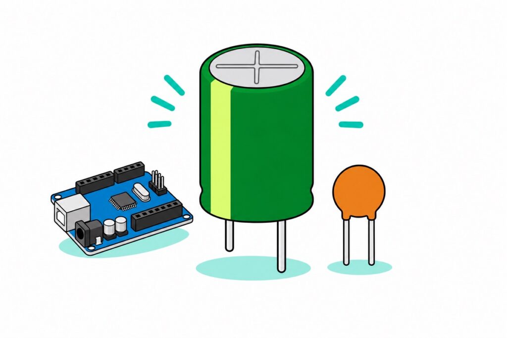
On an electrolytic capacitor (elco), the long leg is positive and the short leg is negative — and the stripe on the sleeve always marks the negative side, the only marking that survives once the legs are trimmed. Ceramic capacitors have no polarity. A code like 104 reads “10 plus four zeros” in picofarads, which is 100nF, and the voltage rating is a ceiling, not a target: for a 5V circuit, pick a 16V capacitor or higher.
What does a capacitor do in an Arduino or ESP32 circuit?
A capacitor is a tiny charge reservoir: two metal plates separated by an insulating layer (the dielectric). Connect it to a voltage and electrons pile up on one plate while being pushed off the other — it “fills” like a mini tank. No electron crosses the insulator: current only flows while the plates are charging or discharging, which is why a fully charged capacitor blocks DC. And because its voltage is set by the stored charge (V = Q ÷ C), while charge can only move in or out as fast as the circuit lets current flow, the voltage across a capacitor cannot jump instantly — which is exactly what makes it useful.
That one property gives you three jobs you will meet again and again: smoothing (patching dips in a power supply — the tank fills while the supply is healthy and pours out when it sags), decoupling (a mini supply sitting right beside a chip), and timing (the time it takes to charge through a resistor becomes the circuit’s clock). Three of our guides already tell you to fit a capacitor for the first two jobs: 10–100µF across the NRF24L01 radio, the big capacitor that rescues a SIM800L, and anti-brownout smoothing for the ESP32. After this page, every one of those “put a capacitor here” instructions will make sense.
This video animates how charge builds up between a capacitor’s two plates:
For hands-on practice, our electronics starter kit has it all: a green electrolytic (its sleeve is printed 100µF and 50V), small ceramic capacitors, an 830-hole breadboard, jumper wires, resistors, LEDs and buttons — and the Arduino Uno serves as the 5V source (USB Type B cable included). The Uno board is itself a live example of this topic: two electrolytics stand beside its barrel jack. No board yet? Get the kit version with an Uno R3 or with an ESP32 instead.
Parts list: identify capacitors, read their codes and watch them work
 Electronic Component Set Beginner Electrical Learning Kit For Arduino Beginner Learning - ELECTRICAL STARTER KIT
 Arduino Uno Compatible SMD UNO R3 with Type B Cable - ATMEGA328P with CH340G-Microcontroller Project
Optional: a multimeter for screening capacitors
| Item | Price | Qty | |
|---|---|---|---|
 XL830L Digital Multimeter with backlight Portable Multimeter Electronics ProjectMULTIME | RM25.95 |
The XL830L has no capacitance range — use its ohms range for the charge 'kick' test and its DC volts range to confirm a capacitor is discharged, as in our capacitor testing guide.
Which capacitor leg is positive and which is negative?
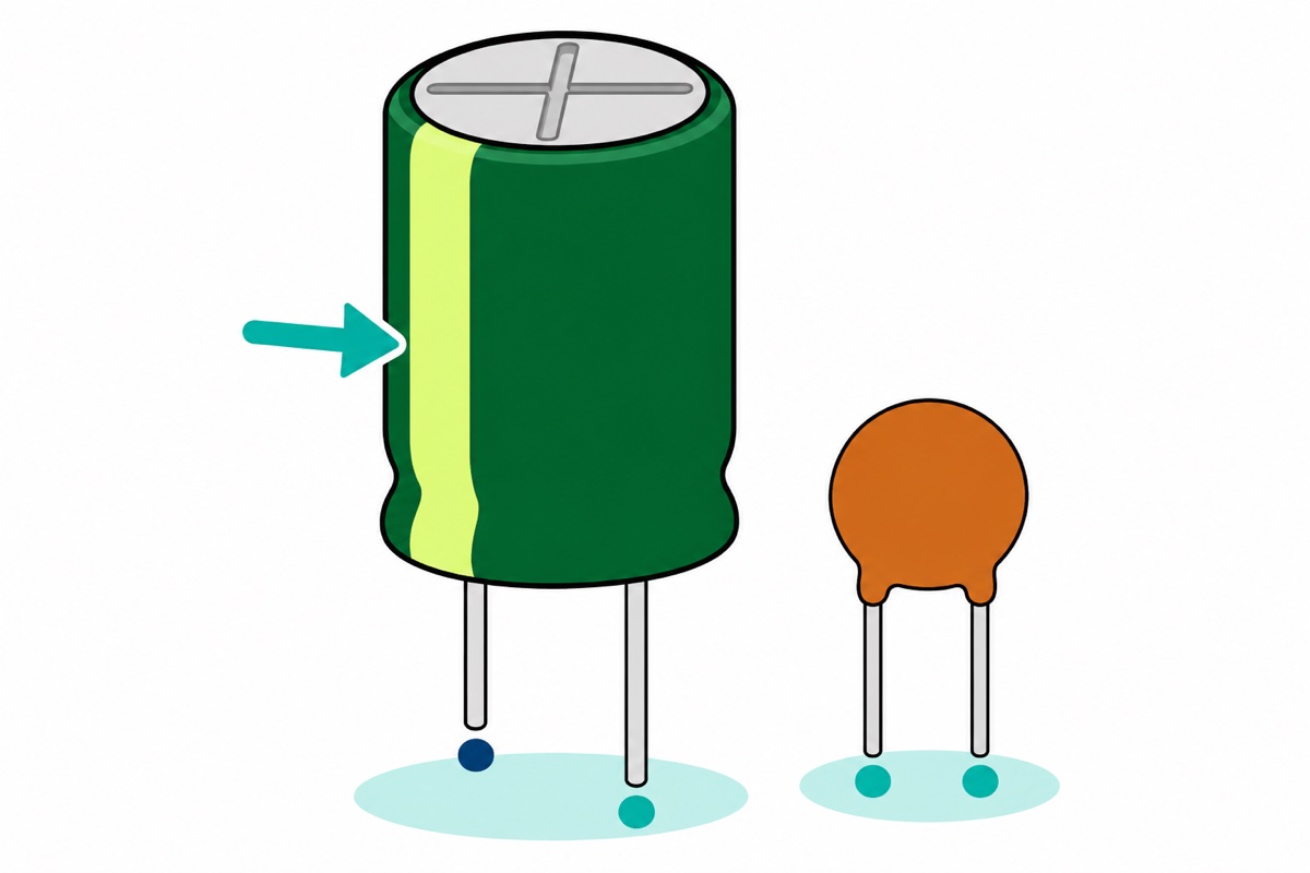
On an electrolytic, three markings point to the same answer: long leg = positive, short leg = negative, and the stripe on the sleeve = the negative side. On the kit’s green electrolytic, the stripe is a pale band running down one side of the sleeve — the leg beneath it is the negative leg. Leg length can only be trusted on new parts: once the legs are trimmed or the part is pulled from an old circuit, the stripe is the only witness. One exception: tantalum capacitors (small yellow or orange beads) are polarised too, but the + or stripe on them marks the positive leg — identify the type first, then read its marking.
Why does an electrolytic have polarity when it is “just two metal plates”? Because its insulator is not a sheet of plastic — it is an aluminium oxide layer grown electrochemically on the positive foil only, roughly 1.3 to 1.5 nanometres thick for every volt of its forming voltage — tens to hundreds of nanometres, only a fraction of a micrometre even on a 50V electrolytic. With the right polarity, that layer is a near-perfect insulator. Reversed, it rectifies like a diode: now the negative foil takes the positive voltage, and it has only a natural oxide film good for about 1V — beyond that, heavy current starts flowing through it even at low voltage, as explained in Nichicon’s application guidelines. That thinness is also why an electrolytic packs so much capacitance into a small can.
Ceramic capacitors are symmetrical: two identical metal electrodes sandwich a ceramic dielectric, so there is no “right” way round — fit it either way.
| Type | What it looks like in the kit | Polarity marking | Fitting |
|---|---|---|---|
| Electrolytic (elco) | Cylinder with a green or black sleeve; the green one is printed 100µF 50V | Pale stripe = negative; short leg = negative | Polarity MUST be observed |
| Ceramic / disc | Small orange-brown disc marked with a number code | None | Either way round |
How do you read numbers like 104 on a capacitor?
An electrolytic is big enough to have its value printed in full — the green sleeve in the kit reads 100µF (capacitance) and 50V (voltage rating). A ceramic disc is too small for that, so it uses a three-digit code in picofarads: the first two digits are the number, and the third digit is how many zeros to add. Code 104 means 10 followed by 4 zeros: 100,000pF. Since 1,000pF = 1nF and 1,000nF = 1µF, 100,000pF is 100nF, or 0.1µF — the decoupling value you will meet most often. A letter after the code is the tolerance: J ±5%, K ±10%, M ±20%.
| Code | Working | Value |
|---|---|---|
| 22 | Two digits only = the value as is, no zeros added | 22pF |
| 101 | 10 + 1 zero = 100pF | 100pF |
| 102 | 10 + 2 zeros = 1,000pF | 1nF |
| 103 | 10 + 3 zeros = 10,000pF | 10nF |
| 104 | 10 + 4 zeros = 100,000pF | 100nF (0.1µF) |
| 224 | 22 + 4 zeros = 220,000pF | 220nF (0.22µF) |
| 474 | 47 + 4 zeros = 470,000pF | 470nF (0.47µF) |
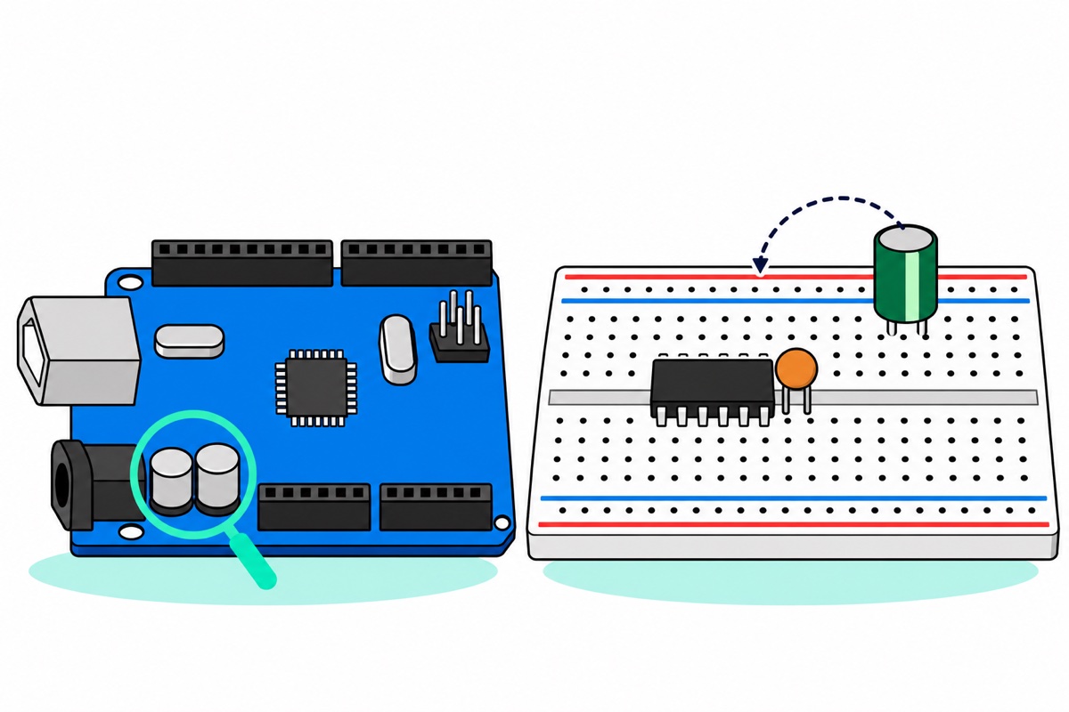
Practise on real parts: take a few ceramic discs from the kit and decode them with the table above. Then look at your Uno board: the two silver cans beside the barrel jack are SMD electrolytics, and on the board in our product photo they are printed 47 and 16V. On an electrolytic, a bare number with no unit is in microfarads — 47µF with a 16V ceiling — and the black half-circle on top of the can is the SMD version’s negative marking, serving the same purpose as the stripe on the green electrolytic. Resistor colour bands are covered in our resistor guide.
What does the voltage rating mean, and why is it a ceiling, not a target?
The voltage rating is the maximum continuous voltage the insulator inside the capacitor can withstand. Remember the oxide layer: it is grown as thick as the rated voltage requires, and every insulator has an electric-field limit — voltage divided by thickness. Past that limit, leakage current climbs steeply — the leakage turns into heat, and the heat speeds up the leakage. A rating higher than you need never damages anything: a thicker insulating layer just needs more foil area for the same capacitance, so the only price is a physically bigger part.
In practice, stay well below the ceiling, because the rating applies to the peak voltage, not the average. Ripple and plug-in surges ride on top of the DC, and the same Nichicon guidelines state that DC plus the ripple peak must not exceed the rating — while a multimeter only shows you the average. For a 5V circuit, a 16V or 25V capacitor is comfortable; the kit’s 50V electrolytic leaves headroom for all our 5V and 12V projects. The opposite direction is the dangerous one — replacing a capacitor with a lower rating than the original is a shortcut to the “bulge and pop” section below.
Why does the 104 ceramic sit next to the chip and the big electrolytic at the supply?
The 104 ceramic and the big electrolytic sit in different places because two kinds of supply dip happen at different speeds. A chip like the ATmega328P or ESP32 changes its current demand within nanoseconds, because its transistors switch together on every clock tick (16 million times a second on an Uno), but current flowing through a long wire cannot change that fast — every wire has inductance, and inductance resists changes in current. In those nanoseconds, the voltage at the chip’s pins dips. The fix is not a stronger supply but a closer reservoir: a 100nF ceramic a few millimetres from the power pin fills that nanosecond gap before the wire can respond. That is why the official Uno R3 schematic places a 100nF ceramic beside its chip’s supply pins.
The big electrolytic wins the opposite job: slower but deeper dips — a radio transmitter’s pulses, the current burst when a GSM module transmits, a motor starting to spin. An electrolytic of hundreds of microfarads keeps pouring out charge long enough for the supply to recover. The two 47µF electrolytics beside the Uno’s barrel jack do exactly this for the board’s regulator. Why can’t an electrolytic do both jobs? Its real negative electrode is the liquid electrolyte, which conducts far worse than metal, and its foils are rolled up long inside the can — that internal resistance and inductance (ESR and ESL) slows its charge delivery at the nanosecond scale, the same problem as the long wire. A ceramic, on the other hand, is a compact stack of thin metal and ceramic layers with almost no internal resistance or inductance, but it holds only a small fraction of an electrolytic’s capacitance. In short: a ceramic is fast but small, an electrolytic is big but slow — a tidy circuit uses both.
How can you watch a capacitor charge and discharge?
Two demos make a capacitor’s charge visible. Demo one: charge the 100µF electrolytic, then release its charge through an LED. Put the electrolytic’s positive leg in one breadboard row and its negative leg (stripe side) in another, then connect that negative row to the Uno’s GND header with a jumper — without this return path no current flows and the electrolytic will not charge. Charge it from the Uno’s 5V pin through a 220Ω resistor for a second or two, pull out the 5V wire, then connect an LED (long leg to the positive side) in series with the same 220Ω across the electrolytic: the LED flashes bright and dies almost instantly. That speed is not a failure — it is maths: the discharge time is governed by τ = R × C = 220Ω × 0.0001F ≈ 22 milliseconds, and the stored energy ½CV² at 5V is only about 1.3 millijoules. This reservoir really is small — enough to patch a supply dip, not to power a circuit.
Demo two turns that discharge curve into a graph — and this is the timing job. Use a large resistor, around 10kΩ (read its colour bands, or measure it), so the discharge is slow enough to watch, and put everything on the a–e half of the breadboard:
| Step | From | To |
|---|---|---|
| 1 | 100µF electrolytic positive leg (long leg) | Breadboard row 10 |
| 2 | Electrolytic negative leg (stripe side) | Row 12 |
| 3 | ≈10kΩ resistor | Row 10 → row 12 (in parallel with the electrolytic) |
| 4 | Male-to-male jumper: row 12 | Uno GND header |
| 5 | Jumper: row 10 | Uno A0 header |
| 6 | 220Ω resistor: row 5 → row 10; jumper from 5V to row 5 | Touch to charge, pull out to discharge |
Using the ESP32 kit? Charge from the 3V3 pin, never 5V: an ESP32 GPIO input only tolerates up to VDD + 0.3V (3.6V), according to the ESP32 datasheet, and an electrolytic charged from 5V will push 5V straight into the ADC pin. Connect row 10 to GPIO36 (labelled VP, which is A0 in the sketch), and change (5.0 / 1023.0) to (3.3 / 4095.0), because the ESP32’s ADC is 12-bit. τ stays at 1 second, because the time constant does not depend on voltage.
Upload this sketch (9% of the Uno’s flash) and open the Serial Plotter at 115200 baud:
// Capacitor discharge watcher — open the Serial Plotter (115200 baud)
const int PIN_KAPASITOR = A0;   // capacitor + leg to A0

void setup() {
  Serial.begin(115200);
}

void loop() {
  int bacaan = analogRead(PIN_KAPASITOR);      // 0–1023
  float voltan = bacaan * (5.0 / 1023.0);      // convert to volts
  Serial.println(voltan);                      // one point on the graph
  delay(100);                                  // 10 readings per second
}
Touch the 5V jumper and the graph climbs to ~5V; pull it out and the line glides down in an exponential curve. The time constant τ = 10,000Ω × 0.0001F = 1.0 second: within one second the voltage falls to about 37% (≈1.8V), within two seconds to ≈0.7V. Why R times C? A bigger capacitor stores more charge per volt (Q = C × V), so more charge has to drain out; a bigger resistor limits the current that drains it (I = V ÷ R). The curve bends instead of running straight because that current shrinks along with the voltage: every τ, the voltage falls to about 37% of where it was at the start of that interval. Swap the resistor and the curve follows — that is the principle that keeps time in timer and filter circuits: time = resistance × capacitance.
Why does a capacitor bulge or pop?
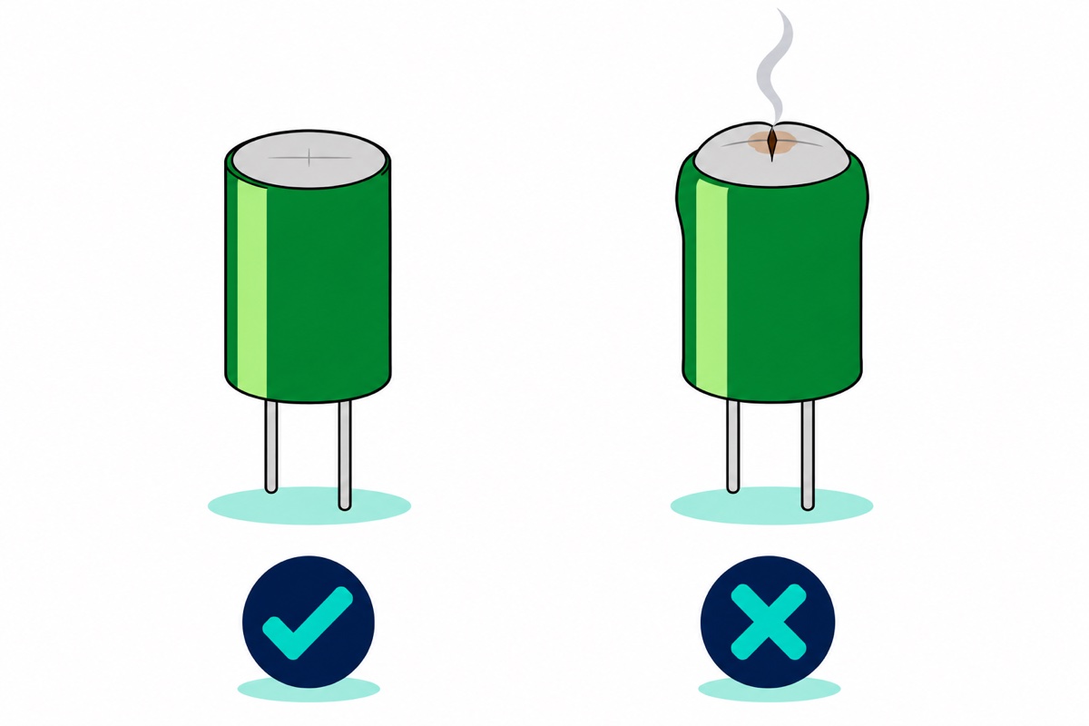
An electrolytic capacitor always fails along the same chain. Reverse polarity or overvoltage forces current through the oxide layer; that current electrolyses the liquid electrolyte inside the can and produces gas; the gas raises the pressure until the aluminium top starts to bulge; and if the pressure keeps rising, the score groove deliberately pressed into the top (where the metal is thinnest) opens as a safety vent — sometimes with a small pop. Never test this on purpose — a venting electrolytic sprays hot electrolyte, and at workbench distance it can reach your face. If an electrolytic in your circuit starts getting hot, hissing or smelling, cut the power immediately and keep your face away until it cools. A bulged electrolytic is already damaged inside: replace it, never reuse it.
Motor capacitors in ceiling fans, air conditioners and washing machines are a different class: they run on AC mains voltage and can hold a dangerous charge even after the plug is pulled. That is a technician’s job, not the topic of this guide, which stays with low-voltage DC circuits only.
Suspect a capacitor is weak or dead? The XL830L has no capacitance range on its dial, but the “kick” test on the ohms range — the reading climbs as the meter charges the capacitor — plus a discharge check is enough for screening. The full steps are in our guide to testing capacitors with a multimeter.
Common mistakes we see
Reading 104 as “104pF” or “104µF”. The three-digit code is not the value itself: the third digit is the number of zeros, in picofarads. 104 is 100,000pF = 100nF. Values printed in full (like 100µF on an electrolytic) are read as they are — two systems, don’t mix them up.
Replacing with a lower voltage rating. A 25V part swapped for a 10V one because “the µF is the same” — right capacitance, wrong ceiling. The rating must be equal to or higher than the original; higher just means bigger.
Fitting decoupling far from the module. A capacitor at the far end of a 20cm jumper wire does nothing for the chip that needs it — the wire in between is exactly the problem it is meant to solve. Place the reservoir physically close to the module’s power pins, as shown in our NRF24L01 guide.
FAQ
Which side of a capacitor is positive and which is negative?
On an electrolytic: long leg positive, short leg negative, and the stripe on the sleeve always marks the negative side — trust the stripe once the legs are trimmed. Ceramic capacitors have no polarity; fit them either way round.
What does the number 104 on a capacitor mean?
The first two digits plus that many zeros, in picofarads: 10 + 4 zeros = 100,000pF = 100nF = 0.1µF. This is the standard decoupling value placed next to a chip’s power pins.
Can I use a capacitor with a higher voltage rating than my circuit voltage?
Yes — the rating is a ceiling, not a match. A 50V capacitor works perfectly in a 5V circuit; the only cost is a bigger size. What you must not do: use a rating lower than the circuit voltage.
Why is the top of my electrolytic capacitor bulging?
Gas has formed inside it — usually from reverse polarity, voltage above the rating, or ageing. A bulged electrolytic is dead: replace it with the same µF value and an equal or higher rating, and check polarity before powering up again.
How many capacitors do I need for one module?
Follow the module’s own guide. The usual pattern is one 100nF ceramic close to the power pins for nanosecond gaps, plus an electrolytic for modules that draw sudden bursts of current, because their dips are deeper and slower: 10–100µF for a radio like the NRF24L01, 470–1000µF for a GSM module like the SIM800L.
Last updated November 2026. Stuck? Chat with us on WhatsApp.
