

Tutorials
PCA9685 16-Channel Servo Driver with Arduino: Run Many Servos Without Brownouts

Aug
Servos brown out an Arduino because they pull amps from a rail rated in milliamps — and the PCA9685 fixes that by making the servo supply a separate rail the board never carries. Two I2C wires carry the commands, a screw terminal carries the current, and each of the 16 channels gets its own pulse in 12-bit steps you calibrate per servo.
Why does adding a third servo reset your Arduino?
The Arduino Uno‘s 5 V pin is not a power supply — it is the tail end of one. On USB, everything the board hands out has already passed through a 500 mA resettable polyfuse (a Bourns MF-MSMF050-2) that sits in series with the USB 5 V line — a USB 2.0 port is only obliged to deliver 500 mA anyway.
Now price a servo against that. A 9 g SG90 idles near 10 mA, draws roughly 100–250 mA while it moves and 360 mA measured at stall. One is comfortable. Two are tolerable — our joystick pan-tilt guide runs exactly two and already reaches for a battery. Four moving at once ask for 400 mA to 1 A, and a servo’s worst moment is the first millisecond of every move, when the motor is barely turning and behaves almost like a short across the rail.
What you see is a chain, not a single fault: the rail sags, the ATmega328P’s brown-out detector holds the chip in reset, the sketch restarts mid-move, and if the sag reaches the USB side the host drops the serial port and your COM port vanishes from the IDE. Same family as our SIM800L brownout guide: nothing is broken, the supply is being asked for current it was never built to give.
Parts list — four servos on their own power rail
 16 Channel PWM Servo Motor Driver PCA9685 16 PWM Output with I2C Communication For Arduino Robotic
 Arduino Uno Compatible SMD UNO R3 with Type B Cable - ATMEGA328P with CH340G-Microcontroller Project
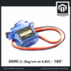 SG90 MG90 Tower Pro Micro Servo Motor 9g 180 360 Servo Motor for Arduino Robotic - SG90- 180°
 40pcs Dupont Wire 10cm 20cm 30cm for Breadboard DIY Experiment Jumper Wire Breadboard wire - DUPONT WIRE M-F 20CM
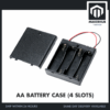 AA Battery Holder with Cover On/Off Switch 2/3/4 Slots Battery AA Holder Red/Black Wire - AA BATTERY CASE (4S)
Worth adding
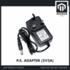 Power Supply Adapter DC Universal AC to DC Converter PSU 5V2A 5V3A 9V2A 12V2A - P.S. ADAPTOR (5V3A)
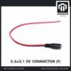 5.5x2.1mm DC Power Male Connector Plug Jack Adapter for Arduino DIY Electronics Projects - 5.5x2.1 DC CONNECTOR (F)
 Data Cable Type-A Type-C MicroUSB Type-B 0.5m 1m 30cm 0.3m 100cm Data Transfer Upload Code - TYPE-A TO TYPE-B (1.0M)
The 5 V 3 A wall adapter is the bench upgrade once four servos becomes eight, or once you move up to metal-gear servos that pull more. It needs the female 5.5x2.1 barrel pigtail beside it: the adapter's plug pushes into the socket, and the pigtail's bare red and black leads land in the driver's screw terminal, same as the battery leads. The spare A-to-B cable is the one that programs the Uno.
How does the PCA9685 keep servo current out of the Arduino?
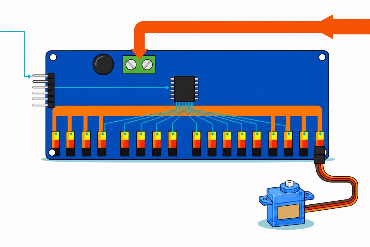
The PCA9685 board has two power inputs that never meet, and that separation is the entire product. VCC, on the six-pin right-angle header, feeds only the PCA9685 chip and its I2C pull-ups — milliamps, which the Uno can spare all day. V+, on the green screw terminal at the top of the board, runs in a fat copper trace straight to the middle (red) pin of all sixteen channel headers. Servo current flows battery → screw terminal → red pin → servo and back, never through the chip. The fat black capacitor beside that terminal sits across the same rail and buffers the first milliseconds of each move, taking the sharpest edge off the surge before the battery leads see it.
All the chip does is switch the third pin — the yellow signal pin — between 0 V and VCC. A servo’s signal input draws microamps, so the PWM chip’s own job stays tiny while sixteen motors drag amps past it on the copper next door.
Grounds still have to be common, and here they already are. The Uno’s GND lands on the six-pin header, the battery’s black lead lands in the screw terminal, and both arrive on the same ground plane inside the board — the board is the common ground, so you add no extra jumper. It matters because a PWM pulse is a voltage difference measured against ground: let the servo’s zero and the Arduino’s zero sit at different potentials and the servo measures a different pulse height than the driver sent, which arrives as jitter you will blame on your code.
The driver’s I2C header is presoldered right-angle male pins and the Uno’s A4/A5 are female sockets, so every wire here is a male-to-female jumper — no breadboard, nothing to solder (our jumper wire guide works that arithmetic through).
| From | To | Why |
|---|---|---|
| Driver GND | Uno GND | Shared zero for the signal pulses |
| Driver SCL | Uno A5 | I2C clock — the populated socket, not the bare pad block |
| Driver SDA | Uno A4 | I2C data |
| Driver VCC | Uno 5 V | Logic supply for the chip only, a few milliamps |
| Driver OE | leave unconnected | Active-LOW output enable, pulled low on the board — outputs are live as shipped; drive it HIGH to cut all sixteen at once |
| Battery red lead | Screw terminal V+ | All servo current enters here |
| Battery black lead | Screw terminal GND | Returns here; joins Uno GND on the board |
| Servo plugs | Channels 0–3 | Brown to black pin, red to red, orange to yellow |
Nothing on those three-pin headers is keyed, so a servo plug seats just as happily reversed — and because the red wire lands on the middle pin either way, the mistake looks fine. Brown and orange are what swap: the servo’s ground return ends up on a PCA9685 output rated for milliamps, forcing motor current through the one chip this board exists to keep it out of, while the signal wire sits on ground and never sees a pulse. Check the brown wire sits on the black bottom row of each channel, and switch the battery pack on only after every servo is seated.
The Uno also carries an unpopulated 3 × 4 block of plated holes near its top edge silkscreened SCL/SDA/5V/GND. Those are bare holes, not sockets — a jumper pushed in touches nothing. A4 and A5 in the analog bank are the same two I2C signals, already socketed.
What should feed the V+ screw terminal?
The PCA9685’s V+ terminal wants 5–6 V DC, the range Adafruit specifies for the PCA9685 with servos on it, and the window is set by the servos, not the board. Hobby servos are built for 4.8–6 V: below about 4.5 V torque collapses and the servo’s own controller starts browning out, while above 6 V you overspeed a motor geared through nylon and shorten its life.
The 4-slot AA holder puts its cells in series, so the chemistry decides where you land. Four NiMH rechargeables at 1.2 V nominal give 4.8 V, squarely inside the window, and NiMH holds that plateau for most of its discharge. Four alkalines are 6.0 V nominal but read nearer 1.6 V each when fresh, so a new set can sit around 6.4 V unloaded — above the top of the window until the first servo pulls it down. Alkalines work; NiMH is the answer that needs no caveat, and voltage is only half of why. The rest is internal resistance: an alkaline AA is built for a torch, not for four motors starting together, and carries several times the internal resistance of an NiMH cell — so the same surge NiMH shrugs off drags an alkaline pack visibly down. That is the identical brown-out, moved off the Arduino and onto the battery.
The holder’s red and black leads end bare, which is exactly what the screw terminal wants — red into V+, black into GND, tightened onto copper and not onto insulation. When four servos become eight, or you move up to metal-gear MG90S servos that pull more (our servo comparison guide covers that choice), swap the batteries for the 5 V 3 A adapter and the female barrel pigtail: 3 A is roughly eight stalled 9 g servos of headroom. Channels are free, current is not: sixteen SG90s moving together is a 4 A ask, so size the supply against the servos you drive at once, not against the channel count. Never jumper the Uno’s 5 V pin across to V+. That hands the servo current back to the rail this board exists to protect, and if a battery is on the terminal as well it ties the two supplies together — a fresh alkaline pack then sits at 6.4 V on the chip’s own VCC pin and back-feeds the Uno, which is how a working driver board gets cooked.
Wiring the terminal and a full fleet of servos, shown at bench speed:
How do 12-bit ticks become a servo angle?
The PCA9685 does not know what a servo is. It knows how to divide a repeating frame into 4096 equal slices and hold each output high for a chosen number of them. Call setPWMFreq(50) and the frame becomes 20 ms long, so one slice — one tick — is 20000 µs ÷ 4096 = 4.88 µs. That single division is the whole translation layer.
So setPWM(channel, 0, N) raises the pin at the start of the frame and drops it N ticks later, giving a pulse of N × 4.88 µs. A 1000 µs pulse is 205 ticks, 1500 µs is 307, 2000 µs is 410. Think in microseconds and convert once — microseconds are what servo travel is specified in.
This is also why copying 150 and 600 as your endpoints, the numbers every example sketch carries, goes wrong. Multiply them out at the exact tick, 20000 µs ÷ 4096 = 4.8828 µs: 150 ticks is 732 µs and 600 ticks is 2930 µs. That span is wider than most 9 g servos travel, so at each end the horn reaches its mechanical stop, the internal controller still sees an error it cannot correct, and the motor keeps pulling near stall current while the servo buzzes. Those numbers are deliberately generous placeholders, not a specification.
Two things stay invisible to arithmetic and obvious to your eyes: individual servos vary by several degrees at the same pulse, and the PCA9685’s prescaler is derived from the chip’s own internal oscillator, which Adafruit’s own library notes lands anywhere in a 23–27 MHz band from chip to chip rather than exactly on the datasheet’s 25 MHz, so the real frame may not be precisely 20 ms.
So calibrate mechanically. Servos ship bare with no horn, so tape a strip of masking tape to the output spline as a flag. Send 1500 µs, then step outward 25 µs at a time and watch it. The moment the flag stops moving — or the servo starts buzzing and warming — you are at the stop. Back off 50 µs, record that endpoint, repeat for the other direction and for each channel.
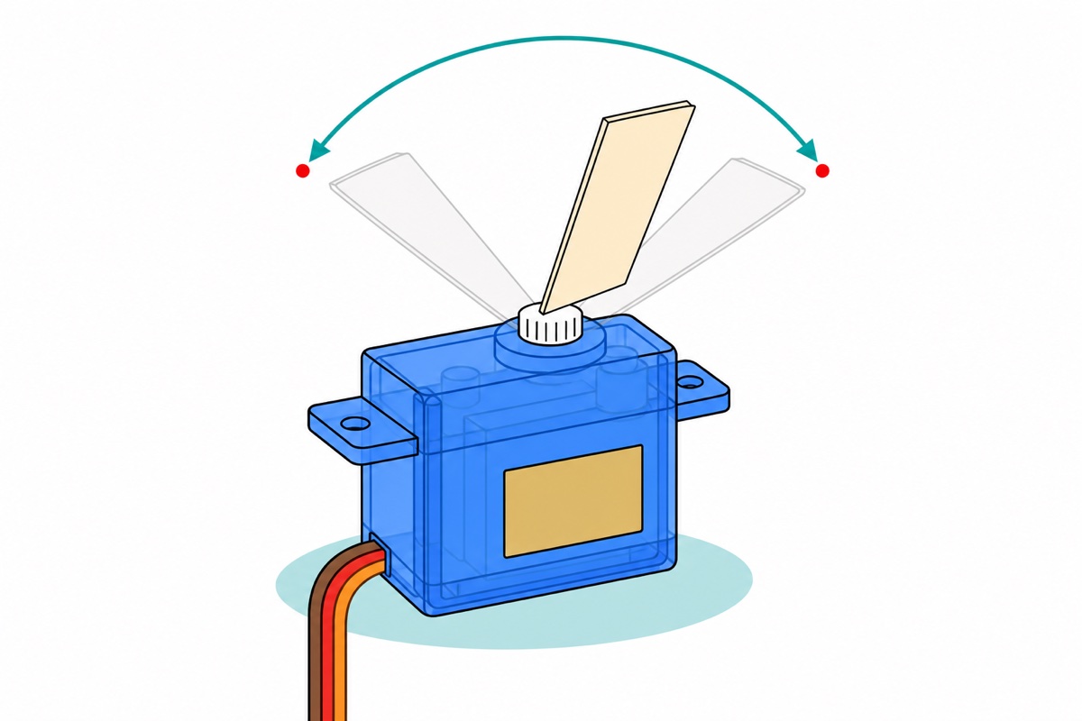
The sketch below is that bench rather than a demo: it takes microseconds over the Serial Monitor, converts them, remembers each channel’s endpoints and then sweeps all four between the numbers you found. Install the Adafruit PWM Servo Driver Library from the IDE’s Library Manager first.
// PCA9685 + Arduino Uno: find each servo's real endpoints, then sweep four at once.
//   Uno A4 -> driver SDA      Uno A5 -> driver SCL
//   Uno 5V -> driver VCC      Uno GND -> driver GND   (logic side, milliamps)
//   Battery holder or 5 V adapter -> driver V+ screw terminal (servo side, amps)
//   Servos plug onto channels 0-3. Uno stays on USB.
//
// Serial Monitor, 9600 baud, "Newline" line ending. Commands:
//   0 1500   send 1500 us to channel 0 (walk this number until the horn stops moving)
//   min 0    remember the current pulse as channel 0's lower endpoint
//   max 0    remember the current pulse as channel 0's upper endpoint
//   sweep    run all four channels between their own endpoints
//   show     print the calibration table

#include <Wire.h>
#include <Adafruit_PWMServoDriver.h>

Adafruit_PWMServoDriver pwm = Adafruit_PWMServoDriver(0x40);

const uint8_t  CHANNELS   = 4;
const uint16_t PWM_HZ     = 50;
const uint32_t PERIOD_US  = 1000000UL / PWM_HZ;   // 20000 us per frame at 50 Hz

// Starting guesses, not safe limits: 1000-2000 us is the NOMINAL FULL travel
// of a 9 g servo (~0 and ~180 degrees), so a given unit may already buzz at one
// end. Narrow or widen these per channel as you calibrate.
uint16_t loUs[CHANNELS] = {1000, 1000, 1000, 1000};
uint16_t hiUs[CHANNELS] = {2000, 2000, 2000, 2000};
uint16_t nowUs[CHANNELS];

// The PCA9685 divides its 20 ms frame into 4096 steps, so one step is
// 20000 / 4096 = 4.88 us. This is the whole conversion.
uint16_t usToTicks(uint16_t us) {
  // + PERIOD_US / 2 rounds to the nearest tick instead of always truncating
  return (uint16_t)((((uint32_t)us * 4096UL) + PERIOD_US / 2) / PERIOD_US);
}

void sendUs(uint8_t ch, uint16_t us) {
  if (ch >= CHANNELS) return;
  if (us < 500)  us = 500;      // search limits, not safe limits: a 9 g servo
  if (us > 2500) us = 2500;     // is already at its stop near 1000 and 2000 us
  nowUs[ch] = us;
  pwm.setPWM(ch, 0, usToTicks(us));
}

void show() {
  for (uint8_t ch = 0; ch < CHANNELS; ch++) {
    Serial.print(F("ch "));      Serial.print(ch);
    Serial.print(F("  now "));   Serial.print(nowUs[ch]);
    Serial.print(F(" us ("));    Serial.print(usToTicks(nowUs[ch]));
    Serial.print(F(" ticks)  min ")); Serial.print(loUs[ch]);
    Serial.print(F("  max "));   Serial.println(hiUs[ch]);
  }
}

void sweep() {
  for (uint16_t p = 0; p <= 100; p += 2) {
    for (uint8_t ch = 0; ch < CHANNELS; ch++) {
      sendUs(ch, loUs[ch] + (uint32_t)(hiUs[ch] - loUs[ch]) * p / 100);
    }
    delay(20);
  }
  for (int16_t p = 100; p >= 0; p -= 2) {
    for (uint8_t ch = 0; ch < CHANNELS; ch++) {
      sendUs(ch, loUs[ch] + (uint32_t)(hiUs[ch] - loUs[ch]) * p / 100);
    }
    delay(20);
  }
  Serial.println(F("sweep done"));
}

void setup() {
  Serial.begin(9600);
  Wire.begin();
  pwm.begin();
  // The PCA9685's internal oscillator is 25 MHz on paper but lands anywhere
  // in a 23-27 MHz band from chip to chip, and the prescaler is computed from
  // that number. 27000000 is Adafruit's own example figure, not a measurement
  // of YOUR chip - which is exactly why the endpoints you find by eye below
  // beat any number computed from it.
  pwm.setOscillatorFrequency(27000000);
  pwm.setPWMFreq(PWM_HZ);
  for (uint8_t ch = 0; ch < CHANNELS; ch++) sendUs(ch, 1500);
  Serial.println(F("ready - try: 0 1500 / min 0 / max 0 / sweep / show"));
}

void loop() {
  if (!Serial.available()) return;

  String line = Serial.readStringUntil('\n');
  line.trim();
  if (line.length() == 0) return;

  if (line == F("sweep")) { sweep(); return; }
  if (line == F("show"))  { show();  return; }

  if (line.startsWith(F("min ")) || line.startsWith(F("max "))) {
    uint8_t ch = line.substring(4).toInt();
    if (ch >= CHANNELS) { Serial.println(F("no such channel")); return; }
    if (line.startsWith(F("min "))) loUs[ch] = nowUs[ch];
    else                            hiUs[ch] = nowUs[ch];
    show();
    return;
  }

  int8_t space = line.indexOf(' ');
  if (space < 0) { Serial.println(F("?")); return; }
  uint8_t  ch = line.substring(0, space).toInt();
  uint16_t us = line.substring(space + 1).toInt();
  if (ch >= CHANNELS) { Serial.println(F("no such channel")); return; }
  sendUs(ch, us);
  show();
}
It compiles to 10,226 bytes, 31% of the Uno’s flash. Calibrate one channel at a time with only that servo plugged in, then plug the rest back and type sweep.
How do two wires drive sixteen channels?
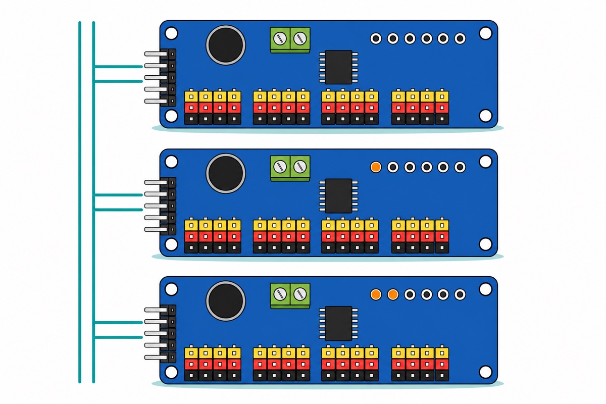
The PCA9685 sits on I2C, which is a shared bus rather than a set of dedicated wires. SDA and SCL run to every device at once and each device answers to an address, so the Uno names the chip it wants before it says anything — which is how an I2C LCD shares these same two pins without a conflict. The PCA9685 answers to 0x40 as it ships.
The six pads marked A0–A5, silkscreened open = 0 and closed = 1, are how you change that. Each is one bit of an offset added to the base address: bridge A0 with solder and the board becomes 0x41, A1 alone makes it 0x42, both make 0x43. Sixty-two boards can therefore share one pair of Uno pins — 992 channels.
That is also the only job here that needs an iron. The chain-out side, the mirrored row of six holes on the right edge, ships unpopulated, and you solder a header there only when a second board joins. For a first build nothing on this parts list requires soldering.
Common mistakes we see from real customers
Running a jumper from the Uno’s 5 V pin to V+. It looks tidy and undoes the entire point of the board — servo current goes straight back through the polyfuse and the brown-outs return unchanged.
Connecting V+ but not VCC. The chip has no logic power, so it never answers on I2C and every channel stays silent. The mirror image, VCC without V+, is harder to spot: the sketch runs, the library reports no error, and the servos merely twitch or sit dead because nothing feeds their red pins.
Copying 150 and 600 from an example sketch. Those ticks span 732–2930 µs, so both ends of every sweep drive the servo into its own stop.
Leaving tired alkalines in the holder. At 1.1 V per cell the pack is down to 4.4 V, and the symptom — juddering under load, fine unloaded — reads exactly like a code problem.
Crossing SDA and SCL. A4 and A5 sit side by side, and swapping them gives a board that answers nothing — the same silence as a dead chip or a missing VCC. Run the IDE’s own File → Examples → Wire → i2c_scanner before debugging anything else: if 0x40 appears, the wiring is right and the fault is in your pulses.
FAQ
Can I power servos from the Arduino’s 5V pin instead?
Only one or two small ones. On USB the Uno’s 5 V comes through a 500 mA polyfuse, and four SG90s moving together ask 400 mA to 1 A — so the rail sags, the brown-out detector resets the chip and the serial port can drop.
What voltage should I connect to the PCA9685 V+ terminal?
5–6 V DC with servos plugged in. Four NiMH AA cells in series give 4.8 V and stay there; a 5 V 3 A adapter is the same answer with more headroom. VCC on the header is separate — 5 V logic power from the Uno, for the chip alone.
What is the PCA9685’s default I2C address?
0x40. The A0–A5 pads add a binary offset when you bridge them with solder — A0 gives 0x41, A1 gives 0x42, both give 0x43 — so up to 62 boards can share one pair of Arduino pins.
How do I convert a servo pulse width into setPWM ticks?
At 50 Hz the frame is 20000 µs and the chip splits it into 4096 ticks, so one tick is 4.88 µs. Divide your pulse by 4.88: 1000 µs is 205 ticks, 1500 µs is 307, 2000 µs is 410.
Why do two identical servos stop at different angles on the same value?
Because hobby servos are built to a price: their internal feedback pots and end stops vary unit to unit. Step each servo’s pulse outward until the horn stops moving, back off, and store that channel’s pair — which is what the sketch above does.
Last updated August 2026. Stuck? Chat with us on WhatsApp.

Pingback: Stepper vs Servo vs DC Motor: Which for Your Arduino?