

Tutorials
Copper Tape Uses: Paper Circuits, EMI Shielding, and Joints That Don’t Fail
Nov
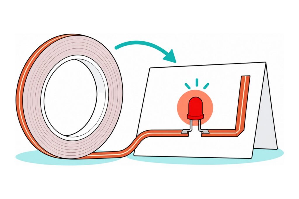
Copper tape is thin copper foil on an adhesive backing. Use it to lay flat circuit traces on paper (LED greeting cards), make capacitive touch pads, shield a guitar cavity or noisy sensor lead, and bridge a broken trace in a pinch. Joints are the weak point: burnish overlaps hard, fold corners instead of cutting, solder anything that flexes.
Our 5mm × 20m conductive copper tape (also called metal conductive tape or metallic copper tape) uses a conductive acrylic adhesive — the foil and the glue both carry current — which is what makes the overlap techniques in this guide work. Below: each use, plus the part most tutorials skip — why joints fail, and how to lay tape so yours don’t.
What is 5mm conductive copper tape actually used for?
Copper tape is a conductor you can stick to almost any dry surface, then tape to, clip to or solder to. Four jobs suit it, each defined by how little current it asks:
| Use | How the tape is used | Current involved |
|---|---|---|
| Paper circuits / LED cards | Flat traces on paper or card; LEDs and battery leads taped or soldered onto them | A few mA — ideal |
| Capacitive touch pads | A patch of tape becomes the pad; a wire or clip connects it to a touch-sensing pin | Microamps — ideal |
| EMI shielding (guitar cavities, sensor leads) | Overlapping strips form a grounded conductive skin around sensitive wiring | Interference only — ideal |
| Bridging a broken trace | A short strip over the break, soldered at both ends for anything permanent | Signal/LED currents — fine; motor currents — no |
The build that teaches every technique at once is the LED greeting card — the parts list below — and it doubles as a school project, because no soldering is required.
Parts list: copper tape LED greeting card
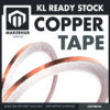 COPPER TAPE 5MM 20M CONDUCTIVE ADHESIVE FOR EMI SHIELDING GUITAR PAPER CIRCUITS
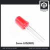 Round Head LED 3mm / 5mm / 8mm - Red/Yellow/Blue/Green/White - 5mm LED (RED)
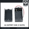 AA Battery Holder with Cover On/Off Switch 2/3/4 Slots Battery AA Holder Red/Black Wire - AA BATTERY CASE (2S)
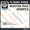 400 pcs 1/4W Resistor Pack Resistor Kit 20 Common Value with 20 each
Parts list
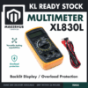 XL830L Digital Multimeter with backlight Portable Multimeter Electronics Project
 Crocodile Clip Cables 46cm Alligator Clip Cable Multi Color
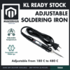 80W Electronics Soldering Iron with LCD Display Ajustable Temperature Microconstroller Electronic Project
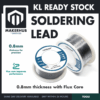 50g Soldering Wire Lead with Flux Core 1mm Diameter
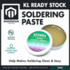 20g Soldering Paste Rosin Flux Lead-Free Blending Easy Solder
For checking joints and soldering the ones that flex — rosin paste makes solder take to copper tape far more easily.
Does the adhesive side of copper tape conduct?
The adhesive on our COPPERC roll is conductive acrylic, rated for dual-sided conductivity: current passes from one strip’s foil, through the adhesive, into the foil underneath — which is what lets overlapped strips behave as one conductor. Not every roll is like this — plenty of copper tape ships with plain insulating glue.
One mechanism explains every reliability rule here. Conductive adhesive carries current through microscopic conductive particles dispersed in the acrylic; pressing a joint squeezes them into a chain of contacts between the two foil faces. The path is particle-to-particle, not solid metal, so a joint always has more resistance than the foil, and that resistance depends on how firmly it was pressed. Hence burnish: rub every overlap down hard with a fingernail or a pen barrel.
Verifying a joint is one multimeter measurement, and good practice before decorating over a trace: resistance mode, one probe each side of the overlap. A burnished overlap on conductive-adhesive tape reads a few ohms or less; plain adhesive reads open — fold or solder that joint instead. Our multimeter guide covers the resistance and continuity modes.
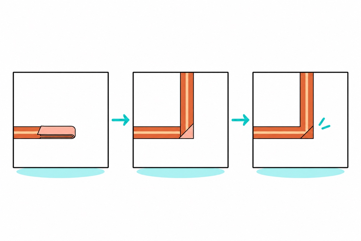
How do you turn a corner by folding instead of cutting?
A folded corner keeps the foil as one continuous piece — that is the whole point. Cut the tape at a corner and start a new strip, and the current must cross an adhesive overlap: a pressure joint that loosens as the paper flexes. A fold has no joint to fail: fold the tape back over itself sticky-side up, crease it, then swing the tape in the new direction and press it flat. The foil runs unbroken around the turn, and at the crease bare foil presses directly on bare foil.
The hand motion is easier to copy than to read — SparkFun’s 25-second clip shows it:
How do you build the LED greeting card?
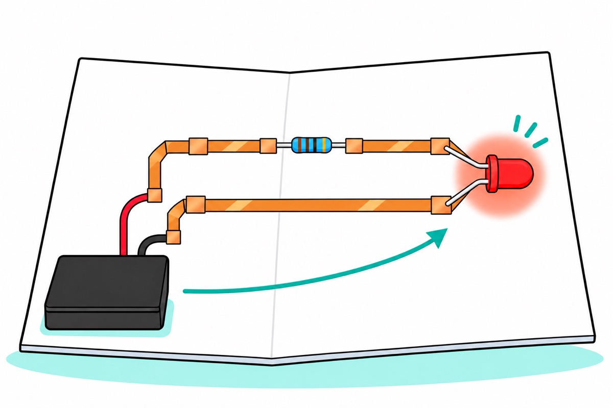
The 5mm red LED card is two copper traces on the inside of a folded card: one from the battery’s positive lead to the LED’s long leg, one from the LED’s short leg back to the negative lead, with the resistor bridging a small gap in the positive trace. Draw the path in pencil first, turn every corner with a fold, and leave a roughly 5mm gap wherever a component will sit — one in the positive trace for the resistor, one between the two traces for the LED. Splayed flat, the LED’s legs look alike, so curl the long (anode, +) leg into a small zigzag before you bend them.
Before sticking anything down, prove the circuit with crocodile clips: clip battery holder, resistor and LED into one chain, flick the holder’s switch, confirm the LED lights. If it stays dark, turn the LED round: reversed, it just blocks current, and 3V is inside the 5V reverse rating typical of 5mm LEDs. The bare metal jaws grip tape and component legs equally well (technique in the crocodile clip guide). A circuit that works in clips but dies on the card tells you the fault is a joint, not a part.
Now the resistor, which overseas coin-cell tutorials make look optional. A CR2032 has a surprisingly high internal resistance (roughly 10–20Ω fresh, climbing past 40Ω as it drains) — a hidden series resistor that limits the LED current in the classic no-resistor card. Two AA alkalines in our 2-slot AA holder give the same nominal 3V with only a fraction of an ohm inside, so nothing limits the current, and a red LED (about 1.8–2V forward drop) wired straight across will blow past its roughly 20mA rating. An LED is not a resistor: once the voltage passes its forward drop, its current climbs steeply with every extra tenth of a volt, so the ~1V it doesn’t use must be dropped by something in series. A 100Ω resistor from the resistor pack is that something: (3.0 − 1.9) ÷ 100 ≈ 11mA — bright and cool. Anything from 100Ω to 220Ω works; higher is dimmer. Pick 100Ω out of the pack by its bands (brown-black-black-black-brown on a five-band body, brown-black-brown on a four-band one) or just measure it.
The AAs’ low internal resistance cuts both ways: a coin cell can barely feed a short circuit, but two AAs can push amps through one, enough to heat the cells and wires. Keep the two traces apart, never let them cross, and switch the holder off while you work on the card.
| From | To | Joint |
|---|---|---|
| AA holder RED (+) wire, stripped end | Start of the positive trace | Tape the bare wire flat under a patch of copper tape, burnish hard |
| Positive trace | Resistor leg 1 (across the ~5mm gap) | Splay the leg flat along the trace, tape over it, burnish |
| Resistor leg 2 | Rest of the positive trace (across the same gap) | Same taped joint; either resistor orientation is fine |
| End of the positive trace | LED long leg (anode) | Splay the leg flat along the trace, tape over it, burnish |
| LED short leg (cathode) | Negative trace back to the holder’s BLACK (−) wire | Taped joints both ends; the holder’s switch is the card’s on/off switch |
The copper patch over each leg presses leg to trace while its conductive adhesive carries the overlap. The holder is far thicker than the card: stick it to the outside back with double-sided tape, feed its wires through a small slit to the traces, and tape each wire’s insulation down a centimetre before its joint, so a tug on the holder pulls that anchor, not the copper. NiMH’s 2 × 1.2V leaves only about 0.5V for the resistor — roughly 5mA, dimmer; the AA battery guide covers the trade-off.
When should you solder a joint instead of relying on overlap?
The card works without solder — that is the school-project version. Soldering is the upgrade for every joint that moves. The first joints to fail are the flexing ones — LED legs on a card that opens and closes, battery wires near an edge, anything crossing a fold — because flexing works the pressure contact loose. Solder replaces that contact with solid metal.
Copper tape solders like any copper, with one rule: be quick, because the adhesive holding the tape down softens under a lingering iron until the trace lifts. Dab rosin flux paste on the spot — flux strips the oxide so solder wets the foil in a second or two — then touch flux-cored solder wire and the soldering iron (about 300–350°C) to the joint, count one-two, lift. The soldering iron and flux basics guide covers the technique if soldering is new to you. On a school project, soldering is an adult’s step: the tip burns skin instantly, the iron goes back in its stand between joints, and an open window or small fan keeps flux smoke away from faces.
How do you make a capacitive touch pad from copper tape?
A copper-tape touch pad is a patch of tape wired to a touch pin on a classic ESP32 or an ESP32-S3 (the C3 has none). The touch sensor keeps charging and discharging the pad; a finger adds capacitance and slows each cycle, and that slowdown is what it detects. It measures timing, not current, so a few ohms of taped joint make no difference. Overlap three or four strips for a fingertip-sized pad, and keep its lead short: the lead is electrically part of the pad, so a long one reacts to a hand passing nearby. The pad senses through paper, so it can hide under a printed button.
How do you shield a guitar cavity or a sensor lead?
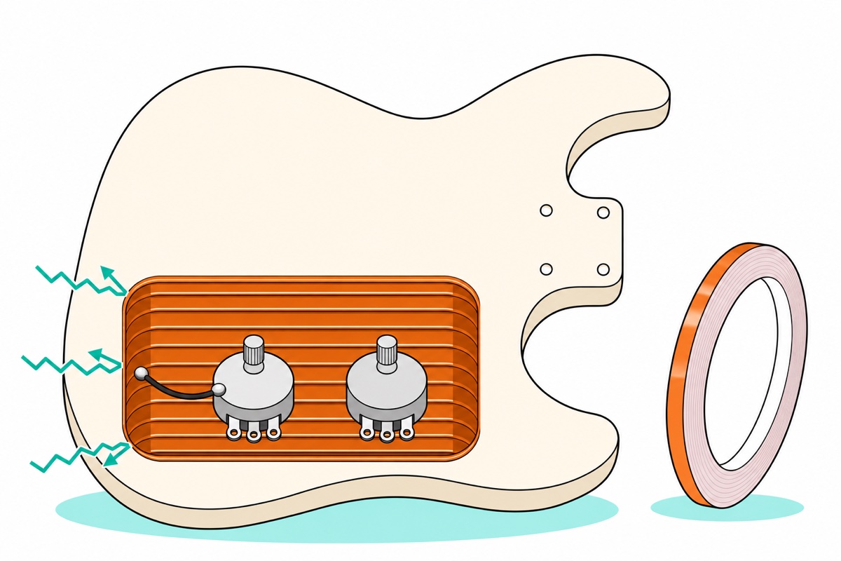
Guitar wiring buzzes because it is high-impedance: pickup and control wiring presents tens or hundreds of kilohms, so even the tiny current that electric fields from mains wiring, dimmers and screens couple capacitively into it develops an audible voltage — Ohm’s law with a very large R. A grounded conductive skin around the cavity intercepts those fields — the interference current drains through the copper to ground instead of riding your signal.
Know the limit before you start: shielding cures electric-field buzz — the kind that drops when you touch the strings — not the steady 50Hz hum a single-coil pickup collects magnetically from transformers and mains wiring. That hum is induced straight into the pickup coil, and thin copper foil is transparent to a low-frequency magnetic field: non-magnetic copper would need to be about a centimetre thick to weaken a 50Hz one. Humbucking pickups exist to fix exactly that.
Four rules make it work. Overlap every neighbouring strip by a couple of millimetres: the conductive adhesive merges the strips into one electrical plane — confirm with a continuity check between the first strip laid and the last. Carry the tape up over the cavity lip, so a shielded cover plate makes contact when screwed down. And ground it: solder one short wire from the tape to the back of a pot casing. An unconnected shield floats: what it intercepts has nowhere to drain, so it removes nothing. Last, keep signal lugs off the walls: the lining is now ground, so a pot’s signal lug, a switch tab or the output jack’s tip terminal touching it shorts your signal and silences the guitar. Bend lugs clear, or cover the nearby copper with insulation tape.
On width, honestly: 5mm is the right tool for seams, cavity lips, small single-coil routs, ground runs between cavities and patching gaps in shielding paint; lining a large cavity floor takes many passes — the 20m length allows it, but wide foil is faster there. For a noisy sensor lead, 5mm is exactly right — spiral-wrap the tape over the lead’s insulation and ground the wrap at the board end only. Bonded at both ends, it becomes a second ground path, and any small voltage difference between the two ends drives current along it, right beside your signal — a ground loop.
Can copper tape bridge a broken trace — and when is it the wrong tool?
A broken PCB trace on an unpowered, low-voltage board takes a copper-tape bridge in a pinch, after two preparations. First scrape the insulating solder mask off a few millimetres each side of the break with a craft knife until bright copper shows (tape cannot conduct through that coating), then wipe it clean. Second, slit the tape narrower: the adhesive conducts, so a full 5mm strip connects to any bare copper it lands on — pads, exposed vias, or a neighbouring trace you scraped by accident. Lay the sliver across the break and burnish hard. For a repair you intend to keep, solder both ends — a pure pressure joint on a board oxidises and creeps loose with temperature cycles — then cover it with insulation tape. On fine-pitch boards, a single strand of wire is easier.
The limits come from joint heating: heat is current squared times resistance. At the card’s 11mA, a full ohm of joint resistance dissipates about 0.1 milliwatt — nothing. At a motor’s 2A, the same joint must shed watts into a spot of acrylic glue, which softens, loses pressure, gains resistance and cooks itself in a feedback loop. Copper tape carries LEDs, logic signals, touch pads and audio grounds happily; it is never a substitute for wire on motors, heaters or power rails, and never a conductor for mains — it is bare, uninsulated metal.
Common mistakes we see
Copying a coin-cell layout onto AA or USB power. No-resistor card layouts survive only because a CR2032’s internal resistance throttles the current. On 2×AA the same layout cooks the LED — add the 100Ω resistor. On 5V USB power, step up to 220Ω: (5 − 1.9) ÷ 220 ≈ 14mA.
Cutting the tape at every corner. Each cut-and-restart is an adhesive joint that loosens as the card flexes. Fold corners; save cuts for gaps a component will bridge anyway.
Laying tape without burnishing it. Conductive adhesive needs pressure to form its particle chain — smoothed on lightly, a joint can read tens of ohms or open; rubbed down hard, near zero. Burnish, then verify with the multimeter.
Shielding a cavity and never grounding it. A floating shield gives interference nowhere to drain. One soldered wire from the copper to a pot casing turns the lining into a shield.
FAQ
Does copper tape conduct through the adhesive side?
Ours does — the COPPERC roll’s conductive acrylic adhesive is rated for dual-sided conductivity, so overlaps connect foil-to-foil through the glue. Rolls from elsewhere often use plain insulating adhesive: test an overlap with a multimeter before trusting it.
Can you solder directly to copper tape?
Yes — it is real copper and takes solder well. Use rosin flux so solder wets in a second or two, and keep the iron contact brief: linger, and the adhesive softens until the trace lifts off the paper.
Why does my paper circuit work with a coin cell but kill the LED on AA batteries?
A CR2032’s internal resistance — roughly 10–20Ω fresh, more as it drains — quietly limits the current, which is why coin-cell tutorials skip the resistor. Two AAs give the same 3V with almost none, so add about 100Ω in series: (3.0 − 1.9) ÷ 100 ≈ 11mA, safely under the typical 20mA rating.
Is 5mm copper tape enough for guitar shielding?
Yes: 5mm suits cavity lips, seams, small routs, ground runs and shielding-paint touch-ups; a big cavity floor takes many overlapping passes. Overlap strips into one plane and solder one ground wire to a pot casing — an ungrounded shield removes nothing.
How much current can copper tape carry?
Treat it as a low-current conductor for LEDs, logic, touch pads and shielding. The limit is the joints: heating grows with the square of the current, so a joint perfect at 11mA destroys itself at motor currents. Use real wire for motors and heaters; never use it near mains.
Last updated November 2026. Stuck? Chat with us on WhatsApp.
