

Tutorials
Digispark ATtiny85 Getting Started: USB Upload, First Blink and a Macro Button
Nov
To get a Digispark ATtiny85 running, install Digistump AVR Boards from ArminJo’s GitHub board URL (the old digistump.com link is dead), select Digispark with the clock set to 16.5 MHz, click Upload with the board unplugged, and plug it in only when the IDE asks. No COM port ever appears, and that is normal. You give up pins and memory — 6 I/O pins, about 6KB of flash — and gain one thing an Arduino Nano cannot do: act as a real USB keyboard.
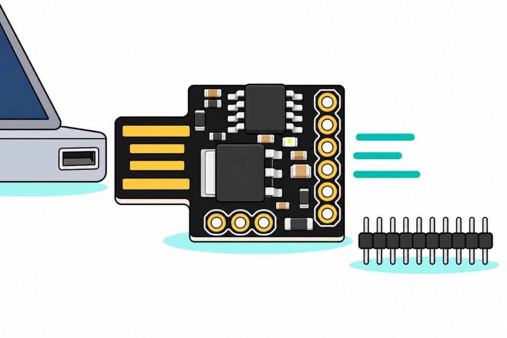
Our Digispark ATtiny85 board is thumbnail-sized, with its USB plug etched into the PCB itself. This guide installs it, blinks the LED, then builds the project the board was born for: a one-key macro button for your PC. Plan a short soldering session first — the male header strip ships loose and unsoldered.
What can a Digispark do that an Arduino Nano can’t?
Next to an Arduino Nano V3, the Digispark loses on pins, memory and debuggability, and wins on size and one genuine party trick. The trick is how each board talks USB: the Nano’s CH340 chip is a fixed-function USB-to-serial bridge, so the computer only ever sees a serial port. The ATtiny85 has no USB hardware at all — instead the Digispark bit-bangs the USB protocol in software (the V-USB technique) on two of its pins, so the chip decides what to introduce itself as. Introduce itself as a keyboard, and it types into any computer with nothing installed there.
| Digispark ATtiny85 | Arduino Nano V3 | |
|---|---|---|
| I/O pins | 6 (3 comfortable — see pin budget below) | 14 digital + 8 analog |
| Flash for your sketch | about 6KB | about 30KB of 32KB |
| SRAM | 512 bytes | 2KB |
| Serial Monitor | none through the USB plug | yes, via CH340 |
| Act as a USB keyboard | yes (software USB) | no (fixed serial bridge) |
| Upload style | plug in when prompted, no COM port | normal COM-port upload |
| Board size | ≈25 × 19mm | ≈45 × 18mm |
Parts list: Digispark USB macro button
 Digispark Attiny85 USB Development Board Arduino Compatible Black Board ATTINY 85 Development
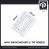 MB102 Breadboard 170 400 830 Holes Breadboard Donut Board Arduino Prototype Multi Color - MINI BREADBOARD 170 HOLES (WHITE)
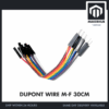 40pcs Dupont Wire 10cm 20cm 30cm for Breadboard DIY Experiment Jumper Wire Breadboard wire - DUPONT WIRE M-F 30CM
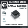 Tactile Button Momentary Switch 6mm x 6mm x 5mm Push Button 4 Pin
Parts list
 Arduino NANO Compatible NANO V3 - ATMEGA328P with C340G - Mini USB - Microcontroller Project
 Round Head LED 3mm / 5mm / 8mm - Red/Yellow/Blue/Green/White - 5mm LED (RED)
 400 pcs 1/4W Resistor Pack Resistor Kit 20 Common Value with 20 each
 80W Electronics Soldering Iron with LCD Display Ajustable Temperature Microconstroller Electronic Project
 50g Soldering Wire Lead with Flux Core 1mm Diameter
Soldering kit for the one-time header job, an LED and resistor pack for an external blink step, and the Nano V3 for projects that outgrow six pins.
How do you install the Digispark board package in Arduino IDE?
Older Digispark tutorials fail at step one: they point the IDE at a package URL on digistump.com, and that domain is dead. The package lives on as ArminJo’s DigistumpArduino fork: its README has marked it unsupported since 2023, but it works with the modern Arduino IDE (2.x) and bundles an updated upload tool plus the Windows driver.
Open File → Preferences → Additional boards manager URLs and paste:
https://raw.githubusercontent.com/ArminJo/DigistumpArduino/master/package_digistump_index.jsonIn Tools → Board → Boards Manager, search Digistump and install Digistump AVR Boards (version 1.7.5 installs cleanly). Select Tools → Board → Digistump AVR Boards → Digispark, then change Tools → Clock from its default 16 MHz – No USB to 16.5 MHz – For V-USB. Low-speed USB sends 1.5 million bits a second, and 16.5 MHz gives exactly 11 clock cycles per bit, the timing V-USB’s hand-counted code is built on. A No USB clock still uploads, since the bootloader always runs at its own 16.5 MHz, but a keyboard sketch built that way compiles cleanly and then never appears as a keyboard.
Windows needs a driver once, because the bootloader identifies itself as a vendor-specific USB device, not a class Windows already drives such as keyboard or serial. It ships inside the package: run post_install.bat (it launches the bundled DPinst64.exe driver installer, or DPinst.exe on 32-bit Windows) from the Digistump_Drivers folder under %LOCALAPPDATA%\Arduino15\packages\digistump\tools\micronucleus\2.6\ (paste that path into File Explorer’s address bar). macOS needs nothing; on Linux, add the micronucleus udev rule so uploads run without sudo.
Why is there no COM port?
Everything strange about this board follows from one fact: USB only exists while code on the chip is bit-banging it, and at power-up, when every upload happens, that code is the bootloader. That bootloader, micronucleus, runs for roughly the first five to six seconds after power-up, advertising the board as a tiny USB device — not a serial port — then hands the chip over to your sketch. Unless the sketch runs its own USB library, nothing answers the computer after that, yet the 1–1.5kΩ pull-up still announces a device, so Windows may show USB device not recognized — expected and harmless with a blink sketch.
The upload tool is built around that window, so the order inverts. Click Upload with the board unplugged; the IDE compiles, then prints “Please plug in the device (will time out in 60 seconds) …”; plug in; the bootloader receives the sketch, writes it to flash and jumps to it.
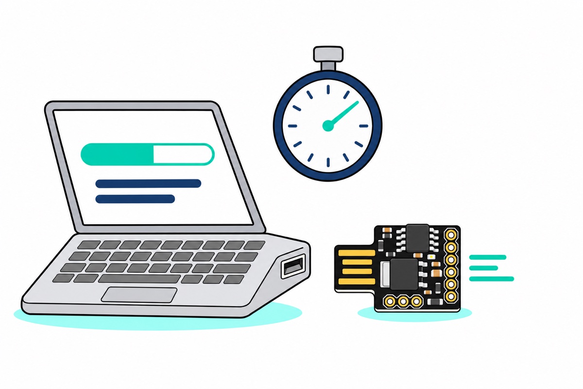
Three consequences look like faults the first time. Tools → Port stays greyed out — there is no port to pick, ever. There is no ordinary Serial Monitor through the plug: the ATtiny85 has no hardware UART, the plug only carries whatever USB device the running code imitates, and the bundled serial-over-USB library (DigiCDC) warns it likely fails on Windows newer than XP and on current Linux kernels. And every power-up starts your sketch about five seconds late, because the bootloader always takes its window first.
How do you blink the onboard LED?
The first test needs no parts. Of the board’s two tiny LEDs, one is the always-on power light; the other sits on P1 on rev3 “model A” boards like this one — the board package itself defines LED_BUILTIN as P1. Clones from other sources come in a second flavour with the LED on P0, so the sketch keeps the pin in one constant; swapping it to 0 is the standard first check when only the power light comes on.
// Digispark first blink - onboard LED on P1 (rev3 "model A" boards).
// If nothing blinks, change LED_PIN to 0: a few clones route the LED to P0.
const uint8_t LED_PIN = 1;

void setup() {
  pinMode(LED_PIN, OUTPUT);
}

void loop() {
  digitalWrite(LED_PIN, HIGH);
  delay(500);
  digitalWrite(LED_PIN, LOW);
  delay(500);
}
Click Upload with the board unplugged, plug in at the prompt, and the LED blinks as soon as the upload finishes, because a fresh sketch starts at once. At 16.5 MHz it compiles to 582 bytes, under a tenth of the budget.
Which of the six pins can you actually use?
“Six I/O pins” is true, but three of the six have day jobs. P3 and P4 carry the USB data lines, so anything wired there fights the USB traffic — and even with USB idle, the 1–1.5kΩ pull-up drags P3 toward 5V while protective zener diodes clip both lines near USB’s 3.3V signal level. P5 is fused to act as reset on most boards: pull it low and the chip reboots. That leaves P0, P1 and P2 as the comfortable workhorses:
| Pin | Comfort level | Notes |
|---|---|---|
| P0 | free | PWM; I2C SDA if you add sensors later |
| P1 | free | PWM; carries the onboard LED, so best as an output |
| P2 | free | analog input (ADC1); I2C SCL |
| P3 | avoid | USB D− with its 1–1.5kΩ pull-up on board |
| P4 | avoid | USB D+; analog ADC2 only in USB-free projects |
| P5 | treat as unavailable | acts as reset on most boards |
For an external-LED step: a 5mm red LED, long leg toward P0, through a 330Ω resistor from the resistor pack to GND, blink sketch pointed at pin 0. The LED drops about 2V, so 3V ÷ 330Ω ≈ 9mA, bright and well within the pin’s limit; on these blue five-band resistors 330Ω reads orange-orange-black-black-brown. Power comes from the USB port’s 5V; away from a computer, feed 7–12V into VIN and the silver tab-shaped 78M05 regulator makes the 5V — if both are connected at once, a diode in the board’s USB supply line keeps the regulator’s 5V from back-feeding your computer.
How do you build the one-key macro button?
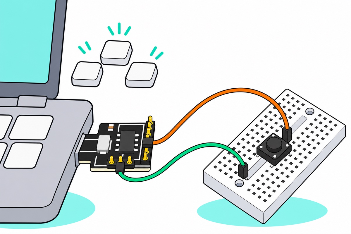
Now the project a Nano cannot copy: a button that types. One press sends a line you retype daily — a customer-service reply, an email sign-off, a meeting link — into whatever window has focus on your own computer, because the computer sees an ordinary keyboard.
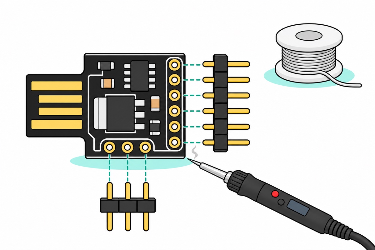
Start at the soldering station: snap the loose header strip into a six-pin and a three-pin length and solder them into the P5–P0 column and the 5V/GND/VIN row (soldering iron, solder wire, and our header soldering guide for the technique). Test-fit the bare board in your USB port first, note which face is on top, and solder the pins pointing up from that face: a laptop port leaves about a centimetre below the board, too little for downward pins plus jumper housings. Park the hot iron in its stand between joints.
The layout quirk: the Digispark never sits on the breadboard while running, because the whole board lives inside the USB port. Only the button goes on the 170-hole mini breadboard, bridged by two male-to-female jumpers — female ends onto the board’s new pins, male ends into the breadboard. Seat the 6×6mm tactile button straddling the centre channel and wire two diagonally opposite legs: the legs are two pairs joined inside the switch, and opposite corners always sit on different pairs, so only a press connects them (our push-button guide has more on the pairs):
| From | To | Jumper |
|---|---|---|
| Button leg (one corner) | Digispark P2 | M-F jumper, female end on P2’s pin |
| Button leg (diagonal corner) | Digispark GND | M-F jumper, female end on the GND pin |
No resistor is needed: the sketch switches on the ATtiny85’s internal pull-up — a built-in resistor of a few tens of kΩ holding P2 at 5V — so the pin reads HIGH until the button shorts it to GND. The keyboard side is the DigiKeyboard library, already inside the board package:
// Digispark one-key macro button: press = types a saved line into the active window.
// Button between P2 and GND. P2 uses the chip's internal pull-up, so no resistor.
#include "DigiKeyboard.h"

const uint8_t BUTTON_PIN = 2;      // P2 - stays clear of the USB pins P3/P4
bool wasPressed = false;

void setup() {
  pinMode(BUTTON_PIN, INPUT_PULLUP);  // reads HIGH idle, LOW when pressed
}

void loop() {
  bool isPressed = (digitalRead(BUTTON_PIN) == LOW);
  if (isPressed && !wasPressed) {        // fire once per press, not per loop
    DigiKeyboard.sendKeyStroke(0);       // blank report: some older PCs drop the 1st char
    DigiKeyboard.print(F("Thank you for your order. We will share the tracking number shortly."));
  }
  wasPressed = isPressed;
  DigiKeyboard.delay(20);  // debounce AND keeps answering the PC's USB polls
}
Three lines carry the mechanism. The edge check (isPressed && !wasPressed) fires once per press, not once per loop pass — a held button would otherwise keep retyping the line until you let go. sendKeyStroke(0) sends a blank no-keys report first; the library’s own example notes that some older computers otherwise miss the first character after an idle spell. And the loop ends in DigiKeyboard.delay(20) rather than plain delay(), because V-USB must handle each request from the computer within about 50ms or the computer gives up on the keyboard — the library’s delay keeps answering while it waits, and the 20ms doubles as debounce. The whole thing compiles to 2,860 bytes at 16.5 MHz, 43% of the budget.
One character-set note: a USB keyboard sends key positions, not letters, and the computer’s layout setting decides what each position types. The library assumes a US layout by default, so a computer set to another layout gets wrong symbols. Most Malaysian PCs run the US layout; if yours differs, add the matching #define LAYOUT_... line above the include — about two dozen layouts ship with it.
The flip side: the button works because computers trust keyboards completely, so anything that enumerates as one types with your full user permissions. That is a reason to label your own gadgets and never plug unknown USB devices into your machine — not a technique to point at anyone else’s computer.
Common mistakes we see
The board is already plugged in when Upload is clicked. The bootloader only advertises itself in its first seconds after power-up, so a board sitting in the port is invisible and the IDE counts down to a timeout. Unplug, click Upload, plug in at the prompt — a front-panel or extension-cable port makes the ritual painless.
Leaving the clock on its default. Blink works on 16 MHz – No USB, but the macro button then never appears as a keyboard. Select 16.5 MHz and upload again.
Plugging in on cue and still timing out. On Windows, first confirm the bundled driver is installed. Then try another port: V-USB’s software-made signal sits near the edge of USB’s timing limits, and some USB 3 ports reject it where a USB 2.0 port or hub works.
Wiring the project onto P3, P4 or P5. The symptoms confuse — uploads fail, the keyboard disappears, the chip reboots when an input changes — because those pins are the USB data lines and reset. Keep buttons and sensors on P0–P2.
FAQ
Why doesn’t my Digispark show up in the Arduino IDE’s port list?
Because it is not a serial device. The bootloader bit-bangs USB as a small non-serial device for about five seconds after plug-in — the window the upload tool waits for. No COM port and a greyed Port menu are normal.
Can a Digispark replace an Arduino Nano?
For one small job, yes — a button, an LED effect, one sensor, a USB-keyboard gadget. Serial-print debugging, more than three comfortable pins or larger libraries belong on the Nano V3; Wi-Fi projects should start from our ESP32-C3 Super Mini guide instead.
How do I debug without a Serial Monitor?
Blink patterns on the P1 LED for coarse state, and — uniquely on this board — DigiKeyboard.print() your variables with a text editor focused, so the board types its own debug log. Logic that needs continuous serial output is easier developed on a Nano first, then ported.
How much flash does a Digispark sketch really get?
The ATtiny85‘s 8,192 bytes of flash are shared with the bootloader, so a sketch gets what micronucleus leaves behind: 6,650 bytes with the current board package’s bootloader, about 6,012 on boards still carrying an older factory one — which is why an upload can occasionally complain a sketch is too big at a size the IDE accepted.
Does the macro button need software installed on the computer?
No — that is the point of USB HID. Every desktop operating system ships generic keyboard support, so the computer accepts the Digispark as a standard keyboard the moment it enumerates; the driver step earlier is only for uploading on your Windows development machine. The button starts listening about five seconds after plug-in, once the bootloader hands over.
Last updated November 2026. Stuck? Chat with us on WhatsApp.
