

Tutorials
MAX98357A I2S Amplifier with ESP32: Wiring and First Sound
Nov
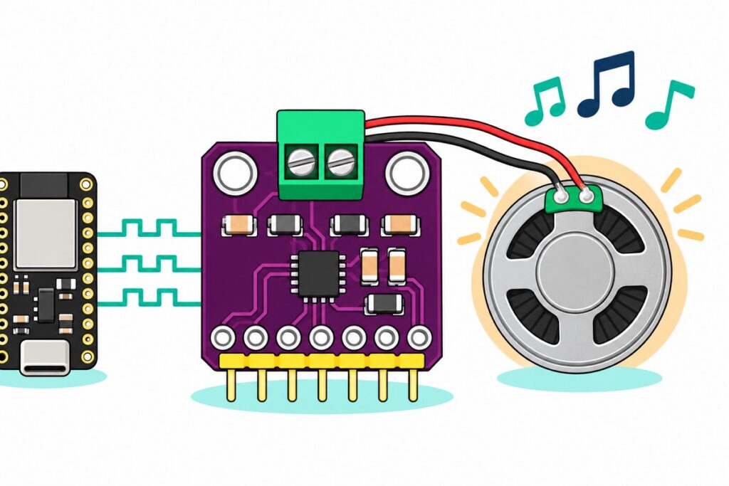
The MAX98357A is a 3W mono class-D amplifier that takes digital audio straight from an ESP32 over three I2S wires. Wire BCLK to GPIO27, LRC to GPIO26, DIN to GPIO25, Vin to the ESP32’s 5V VIN pin and GND to GND, leave GAIN and SD unconnected, and a short sketch plays a clean tone through a small speaker — no DAC module, no analog stage, no volume pot.
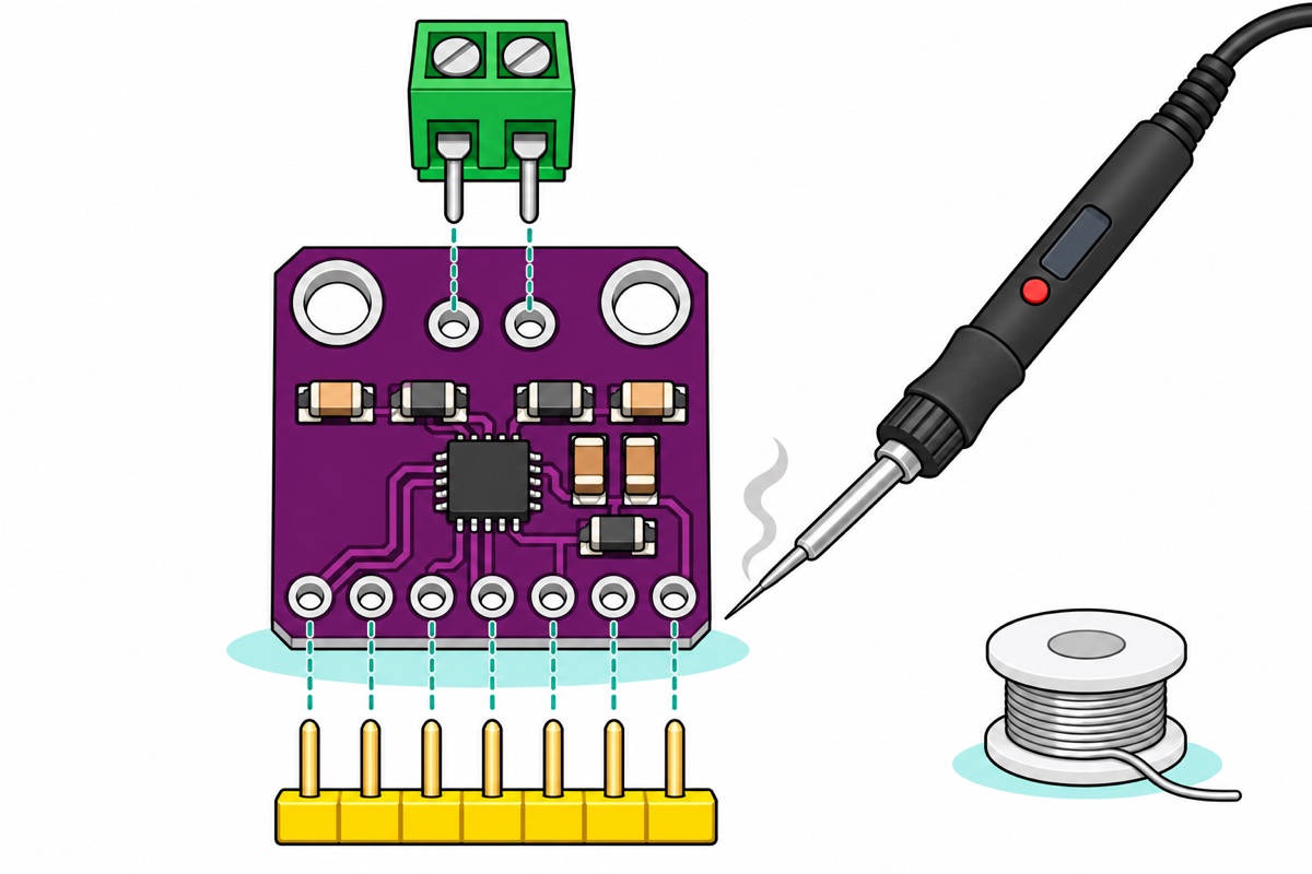
That board is our MAX98357A I2S amplifier breakout — a thumbnail-sized deep-purple module, and the easiest jump from buzzer beeps to speech, alerts and music. Before any wiring: the module ships with its header pins and green screw terminal unsoldered, and the mini speaker’s tabs are bare pads, so plan a short soldering session first — our header soldering guide covers it.
What is I2S, in plain words?
I2S (Inter-IC Sound) is a three-wire digital connection that moves finished audio samples from one chip to another. BCLK is a metronome ticking about 1.4 million times a second; on every tick, DIN carries one bit of the current sample; LRC flips low and high to say whether those bits belong to the left or the right channel. Sixteen bits per sample, 44,100 samples per second, two channels — multiply it out and you get that 1.41MHz bit clock, all generated by the ESP32’s hardware while your code does other things.
Because the wires carry only ones and zeroes, the link is close to noise-proof. In an analog audio setup, every millivolt of interference a cable picks up is added to the music and then amplified; on an I2S line, picked-up noise rides on top of a 3.3V square wave and changes nothing unless it drags the line past the chip’s input thresholds — below 0.6V reads as 0, above 1.3V as 1 — and stray hum is measured in millivolts. That is why jumper neatness barely matters here, and why the digital-to-analog conversion happens inside the MAX98357A itself, millimetres from the speaker terminals, with no cable left to pollute. The same thresholds let the ESP32’s 3.3V signals drive a 5V-powered amp directly, with no level shifter.
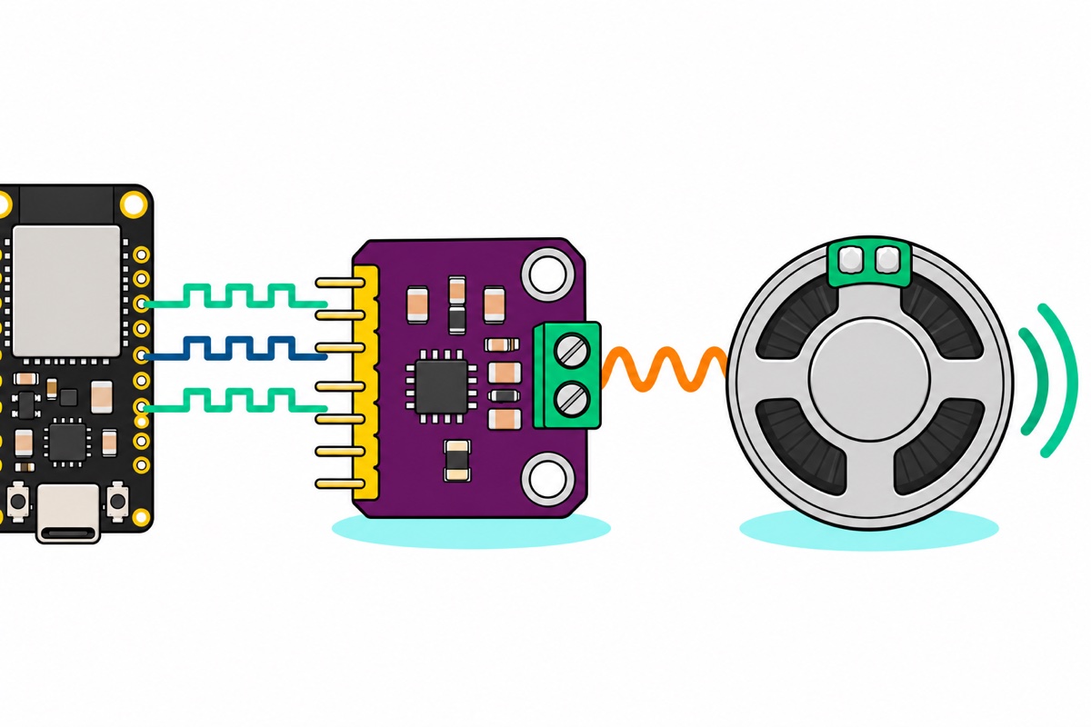
The MAX98357A also needs no MCLK, the fourth high-speed master-clock wire many I2S DACs demand, so three data wires and two power wires are the whole interface.
Parts list: MAX98357A first-sound build
 MAX98357A I2S 3W CLASS D AUDIO AMPLIFIER BREAKOUT BOARD FOR RASPBERRY PI ESP32
 NodeMCU ESP32 Wi-Fi + Bluetooth Development Board CH340/CP2012 - For IOT Project - ESP-32 (CH340)
 8 Ohm 0.5W Mini Speaker Small Round Audio Speaker for Arduino DIY Projects Electronic Components Sound Module
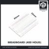 MB102 Breadboard 170 400 830 Holes Breadboard Donut Board Arduino Prototype Multi Color - BREADBOARD (400 HOLES)
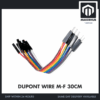 40pcs Dupont Wire 10cm 20cm 30cm for Breadboard DIY Experiment Jumper Wire Breadboard wire - DUPONT WIRE M-F 30CM
 Data Cable Type-A Type-C MicroUSB Type-B 0.5m 1m 30cm 0.3m 100cm Data Transfer Upload Code - TYPE-A TO TYPE-C CABLE (0.5M)
Parts list
 80W Electronics Soldering Iron with LCD Display Ajustable Temperature Microconstroller Electronic Project
 50g Soldering Wire Lead with Flux Core 1mm Diameter
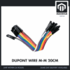 40pcs Dupont Wire 10cm 20cm 30cm for Breadboard DIY Experiment Jumper Wire Breadboard wire - DUPONT WIRE M-M 20CM
Needed once: the amp's header pins and screw terminal — and the speaker's tabs — ship unsoldered. M-M jumpers help for breadboard rail links.
Where do the five wires go?
The MAX98357A module’s bottom edge carries seven pins, silkscreened left to right as LRC, BCLK, DIN, GAIN, SD, GND, Vin. A first build uses five of them:
| Amp pin | ESP32 pin | What it carries |
|---|---|---|
| Vin | VIN | 5V from the USB cable — not 3V3 (see below) |
| GND | GND | Shared ground |
| BCLK | GPIO27 (D27) | Bit clock — one tick per bit |
| LRC | GPIO26 (D26) | Left/right select — one flip per sample |
| DIN | GPIO25 (D25) | The sample data itself |
| GAIN | leave unconnected | Reads 9dB gain when floating |
| SD | leave unconnected | Onboard parts already select mono mix |
GPIO27, 26 and 25 are a convention, not a requirement: the ESP32 routes its I2S peripheral through an internal GPIO matrix, so almost any output-capable pin works. These three sit together on the same edge as VIN and GND, and they are the pins in the most-used ESP32 audio library’s own README example, so borrowed code works unmodified.
The 30-pin ESP32 board itself stays off the breadboard: straddling a 400-point breadboard it leaves at most one free hole beside each pin and fills 15 of the board’s 30 rows (how a breadboard works shows why). So seat the amp’s header in the breadboard, sit the ESP32 beside it, and join them with male-to-female jumpers: female ends onto the ESP32’s pins, male ends into the same numbered rows as the amp’s pins. The speaker hangs off the amp’s screw terminal.
Power the amp from the ESP32’s VIN pin, which carries the USB cable’s 5V, never from 3V3. The chip runs on anything from 2.5V to 5.5V, but a class-D output’s power scales with the square of its supply — the datasheet’s 8Ω figure falls from 1.8W at 5V to 0.93W at 3.7V — and the 3V3 pin sits behind the board’s small regulator, which already feeds the ESP32’s Wi-Fi bursts. Our ESP32 power guide covers that budget in detail.
What do the GAIN and SD pins actually do?
Neither GAIN nor SD on the MAX98357A is a digital input. Both are read as analog voltage levels against internal comparator thresholds, set by how the pin is strapped with resistors — which is exactly why wiring copied from a different board can give silence or whisper-quiet output with no error anywhere: the straps differ, so the chip is in a different mode.
GAIN selects one of five fixed gains, per the MAX98357A datasheet:
| GAIN pin strap | Gain |
|---|---|
| 100kΩ resistor to GND | 15dB |
| Wired straight to GND | 12dB |
| Left unconnected (this module’s default) | 9dB |
| Wired straight to Vin | 6dB |
| 100kΩ resistor to Vin | 3dB |
SD is named for shutdown, but it is really a four-band mode pin with an internal 100kΩ pulldown:
| Voltage on SD | What the amp does |
|---|---|
| Below 0.16V | Shutdown — output off |
| 0.16V – 0.77V | Plays (left + right) ÷ 2 — a mono mix |
| 0.77V – 1.4V | Plays the right channel only |
| Above 1.4V | Plays the left channel only |
This breakout ties SD to Vin through the small black resistor printed 105 (1MΩ), which forms a voltage divider with that internal 100kΩ pulldown: 5V × 100k ÷ 1.1M ≈ 0.45V, squarely inside the 0.16–0.77V band. So straight out of the bag the module plays (left + right) ÷ 2 — and there is the number-one unboxing surprise: the MAX98357A is a mono amplifier. One speaker, both channels mixed. True stereo takes two modules on the same three I2S wires: SD tied straight to Vin plays left (5V is far above 1.4V), while a 560kΩ resistor from SD to Vin, in parallel with the onboard 1MΩ, sets about 1.1V and plays right.
Which speaker should you pair with it?
The MAX98357A delivers 3.2W into 4Ω and 1.8W into 8Ω from a 5V supply (at 10% THD), because its bridge-tied-load (BTL) output drives the speaker between two outputs swinging in opposition — the speaker sees nearly twice the voltage swing one 5V output could give, and power is voltage squared over resistance. A 4Ω 3W full-range driver is therefore the natural partner, and the drivers inside retired Bluetooth speakers and musical toys are very often exactly that — worth salvaging before you bin one. At full power, though, the amp draws roughly 0.7A from 5V (3.2W ÷ 5V, plus its losses), which together with the ESP32’s own Wi-Fi bursts is more than a laptop’s 500mA USB port supplies, so run loud 4Ω builds from a 1A phone charger.
The 8Ω 0.5W mini speaker in the parts list is right for a first tone and for voice alerts, with one honest caveat: the amp can push 1.8W into it, more than triple its rating. The gain strap sets how loud full scale comes out: the datasheet measures gain from a 1.27V RMS reference, so at the 9dB default a full-scale sine reaches about 3.6V RMS, roughly 1.6W into 8Ω. Strapping GAIN to Vin through 100kΩ (3dB) cuts full scale to about 0.4W, inside the speaker’s rating whatever the software sends. At the default, keep software volume low; crank everything and you will eventually smell the voice coil.
The mini speaker’s tabs are bare solder pads, so it needs two leads: cut a spare jumper from the pack into two short lengths, strip both ends of each, solder one end to each tab and clamp the other ends in the amp’s green screw terminal. Swapping speakers later then takes seconds.
One safety rule falls straight out of the BTL topology: both speaker terminals are actively driven, so never connect either one to GND, and never let the two leads touch each other — each of those is a dead short across an output stage. The − and + marks beside the module’s speaker holes mean “this way round”, not “minus is ground”.
How do you get a first tone out?
The first MAX98357A sketch needs no library at all — the Arduino-ESP32 core ships ESP_I2S, which drives the I2S hardware directly. It arrived in version 3.0 of the ESP32 board package, and both sketches here need 3.0 or newer, so check that Boards Manager shows esp32 by Espressif Systems at 3.0 or above; on 2.x this sketch stops at ESP_I2S.h: No such file or directory. Then select ESP32 Dev Module and upload over a data cable.
// MAX98357A first-sound test: a clean 441 Hz tone, no library needed.
// Board: ESP32 Dev Module (30-pin NodeMCU-style, CH340, USB-C)
#include <ESP_I2S.h>
#include <math.h>

const uint8_t PIN_BCLK = 27;   // amp BCLK
const uint8_t PIN_LRC  = 26;   // amp LRC (word select)
const uint8_t PIN_DIN  = 25;   // amp DIN (sample data)

const uint32_t SAMPLE_RATE = 44100;
const int      FRAMES_PER_CYCLE = 100;   // 44100 / 100 = exactly 441 Hz
const int16_t  VOLUME = 3000;            // ~9% of full scale - gentle on a 0.5W speaker

I2SClass i2s;
int16_t wave[FRAMES_PER_CYCLE * 2];      // one sine cycle, left + right interleaved

void setup() {
  for (int n = 0; n < FRAMES_PER_CYCLE; n++) {
    int16_t s = (int16_t)(VOLUME * sinf(2.0f * PI * n / FRAMES_PER_CYCLE));
    wave[2 * n]     = s;   // left slot
    wave[2 * n + 1] = s;   // right slot - the amp averages the two anyway
  }
  i2s.setPins(PIN_BCLK, PIN_LRC, PIN_DIN);
  i2s.begin(I2S_MODE_STD, SAMPLE_RATE, I2S_DATA_BIT_WIDTH_16BIT, I2S_SLOT_MODE_STEREO);
}

void loop() {
  i2s.write((uint8_t *)wave, sizeof(wave));  // blocks until the DMA buffer takes it
}
Upload, and the speaker holds a steady 441Hz tone. That odd-looking frequency is deliberate: one sine cycle fits exactly 100 samples at 44.1kHz, so the loop replays one small buffer forever with no seam or click. The VOLUME constant sits at about 9% of full scale on purpose: at the 9dB default that is roughly 13mW into the 8Ω speaker, clearly audible and far inside its 0.5W rating. Loudness belongs in software; the gain strap sets the ceiling.
How do you play a WAV or MP3 file?
A tone proves the MAX98357A wiring; a sound file proves the whole toolchain. The go-to library is ESP32-audioI2S, with one version catch: its recent releases are built for PSRAM-equipped chips like the ESP32-S3, and the 30-pin WROOM-32 board here has no PSRAM. In the Library Manager it is listed as ESP32-audioI2S-master — pick version 3.0.13, an older release that still runs on plain ESP32 boards (the author marks 3.2.1 as the last release without PSRAM); its own README example uses these same three pins.
// MAX98357A stage two: play a WAV file from the ESP32's flash (SPIFFS).
// Library: ESP32-audioI2S v3.0.13 (a pre-PSRAM release that runs on plain ESP32 boards)
#include <Arduino.h>
#include <Audio.h>
#include <SPIFFS.h>

Audio audio;

void setup() {
  SPIFFS.begin();
  audio.setPinout(27, 26, 25);   // BCLK, LRC, DIN - same wires as the tone test
  audio.setVolume(8);            // 0-21; start low for a small speaker
  audio.connecttoFS(SPIFFS, "/hello.wav");
}

void loop() {
  audio.loop();                  // feed the decoder; keep loop() free of delays
}
The file itself lives in the ESP32’s own flash: put hello.wav in a data folder inside the sketch folder. Arduino IDE 2 has no built-in uploader for it, so install the free arduino-spiffs-upload plugin, close Serial Monitor, and run Upload SPIFFS to Pico/ESP8266/ESP32 from the command palette (Ctrl+Shift+P, or Cmd+Shift+P on a Mac); the sketch then plays the file at every boot. setVolume() runs 0–21 — start around 8 on the mini speaker.
Export that WAV as 16-bit PCM at 44.1kHz, or 16kHz for voice, never 22.05kHz. The library clocks I2S at the file’s own rate, and while the MAX98357A runs happily at 8, 16, 32, 44.1 or 48kHz, its datasheet lists 11.025, 12, 22.05 and 24kHz as unsupported, so a clip at those rates can play silent or garbled even though the tone test worked. Keep it short, too: the default partition scheme leaves about 1.4MB for files, roughly 15 seconds of 44.1kHz mono. Longer clips belong in MP3, a one-line change through the same connecttoFS() call, and internet-radio streams need only Wi-Fi connection code added.
Common mistakes we see
Total silence with the sketch running. The classic cause is BCLK and LRC swapped: the amp then sees a 44.1kHz bit clock, far below its 243kHz minimum, and a 1.41MHz frame clock, far above its 96kHz maximum, so it never finds a valid frame and stays silent. The second is SD: wiring copied from a schematic that grounds SD holds the amp in shutdown. Both fixes are one jumper.
No COM port, nothing uploads. Not an audio problem at all: a charge-only USB cable, or the missing CH340 driver — the two causes the upload-fix guide walks through.
Hiss between sounds. A gain strap at 12–15dB into a small speaker near your ear amplifies the amp’s own noise floor along with the music. Do the opposite of instinct: strap the gain low (3–9dB) and push the loudness back up in software — the music returns, the hiss doesn’t.
Quiet, distorted, or the board reboots on loud passages. The amp is powered from 3V3. Output power drops with the supply squared, and loud passages now fight the Wi-Fi radio for the board’s small regulator. Move the amp’s Vin jumper to the VIN pin. Already on VIN with a 4Ω speaker? Swap the laptop port for a 1A phone charger.
FAQ
Is the MAX98357A stereo or mono?
Mono. It accepts a stereo I2S stream but plays a (left + right) ÷ 2 mix through one speaker on this breakout. For stereo, feed two modules the same three I2S wires: SD tied straight to Vin on the left-channel board, and a 560kΩ resistor from SD to Vin on the right-channel board.
Can the MAX98357A drive headphones?
No. Its bridge-tied output drives both terminals actively, while a headphone jack grounds the sleeve — plugging headphones in shorts a driven output to common. It is also dangerously loud at the ear: full scale at the 9dB default is around 400mW into 32Ω headphones. For headphone or line-level output, use a ground-referenced I2S DAC board instead.
Do I need to connect the GAIN and SD pins?
Not for a first build. Floating, GAIN reads 9dB, and the module’s onboard resistor already holds SD in the mono-mix band. Strap GAIN to change the loudness ceiling; touch SD only for a stereo pair or a hardware mute.
Which ESP32 pins does the MAX98357A need?
Any output-capable ones — the ESP32’s GPIO matrix routes I2S almost anywhere. GPIO27 (BCLK), GPIO26 (LRC) and GPIO25 (DIN) are the de-facto standard in library examples and wiring guides, so using them keeps borrowed code working.
What speaker works best with the MAX98357A?
A 4Ω speaker rated about 3W collects the full 3.2W the chip delivers at 5V; an 8Ω speaker tops out at 1.8W. Full-range drivers from old Bluetooth speakers are usually 4Ω 3W and pair beautifully. A 0.5W mini speaker suits tones and voice alerts; with GAIN strapped to 3dB, even full scale stays near 0.4W.
Last updated November 2026. Stuck? Chat with us on WhatsApp.
