

Tutorials
LCD1602 I2C with Arduino: Wiring, Library, Address Scan & Blank-Screen Fix
Aug
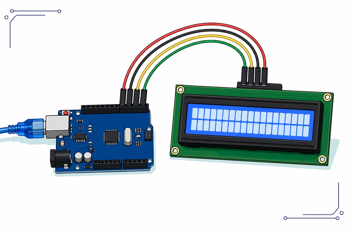
Yes — a 16×2 LCD1602 with an I2C backpack needs only four wires to an Arduino Uno: GND to GND, VCC to 5V, SDA to A4 and SCL to A5, plus one library from Library Manager. This guide wires it solder-free, finds your module’s real address, and fixes the blank-screen and garbled-text traps that fill our support inbox.
Is the I2C chip already soldered onto this LCD?
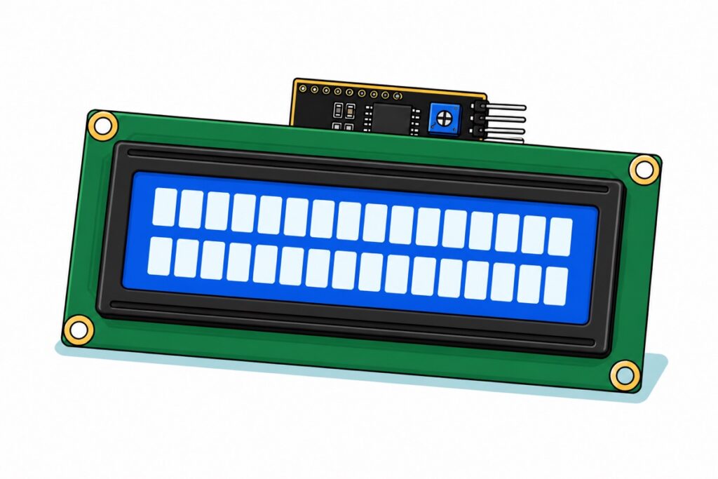
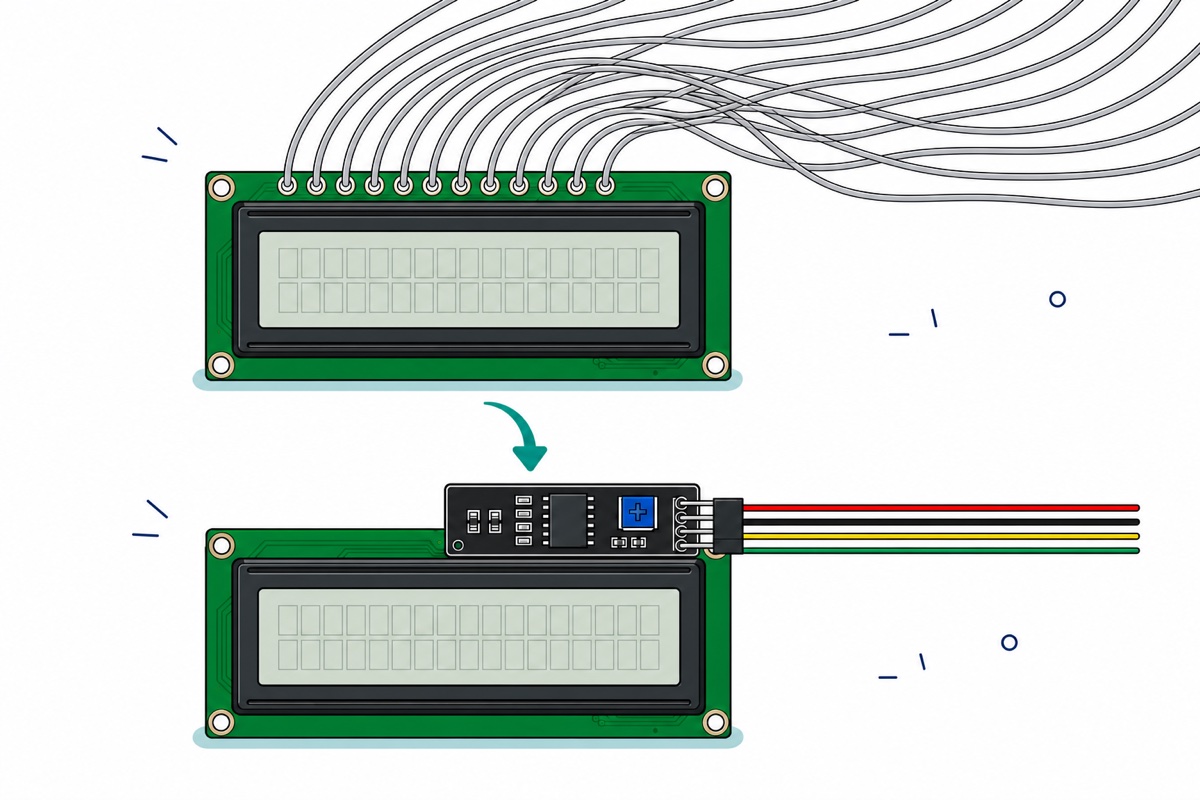
On the 1602 + I2C module, yes — the black I2C backpack arrives already soldered across the display’s 16-pin row. Flip the board over and it is all there: the interface chip, a blue contrast trimmer, a backlight jumper and a right-angle 4-pin header labelled GND, VCC, SDA, SCL. There is nothing to solder anywhere in this build.
The Basic variants are the same display glass without that backpack: a bare 16-pin parallel interface that needs a dozen wires plus your own contrast potentiometer. They are the right buy only when a lesson plan specifically asks for parallel wiring — for everything else, the soldered-I2C version is the one to get.
| Display | Interface | Screen colour | Where |
|---|---|---|---|
| 16×2 | I2C, pre-soldered | White on blue | 1602 + I2C (Blue) — this guide |
| 16×2 | I2C, pre-soldered | Dark on green | Green option on the same product page |
| 16×2 | Parallel, no backpack | Dark on green | 1602 Basic (Green) |
| 20×4 | I2C, pre-soldered | White on blue | 2004 + I2C (Blue) |
| 20×4 | I2C, pre-soldered | Dark on green | Green option on the same product page |
| 20×4 | Parallel, no backpack | White on blue | 2004 Basic (Blue) |
Parts list — the display, the board, the cable and the four wires between them
 LCD1602 LCD2004 Liquid Crystal Display Module with IIC I2C Basic 16x2 20x4For Arduino Display Application - 1602 + I2C (Blue)
 Arduino Compatible UNO R3 FT232 Development Board Arduino Compatible CH340 Alternative
 Data Cable Type-A Type-C MicroUSB Type-B 0.5m 1m 30cm 0.3m 100cm Data Transfer Upload Code - TYPE-A TO TYPE-B (1.0M)
 40pcs Dupont Wire 10cm 20cm 30cm for Breadboard DIY Experiment Jumper Wire Breadboard wire - DUPONT WIRE M-F 20CM
Parts list
| Item | Price | Qty | |
|---|---|---|---|
 LCD1602 LCD2004 Liquid Crystal Display Module with IIC I2C Basic 16x2 20x4For Arduino Display Application - 2004 + I2C (Blue)LCD2004 LCD1602 LCD2004 Liquid Crystal Display Module with IIC I2C Basic 16x2 20x4For Arduino Display Application - 2004 + I2C (Blue)LCD2004 | RM19.95 |
The bigger 20x4 screen. Identical wiring and library — only the constructor line changes to (0x27, 20, 4).
How does the I2C backpack turn 16 pins into 4?
The backpack carries a PCF8574 — an I2C port expander: it listens on the two-wire I2C bus and copies each byte it receives onto eight physical output pins. The LCD’s own controller, the classic HD44780, has a 4-bit mode in which every command arrives as two half-bytes on data lines D4–D7. Eight expander outputs are exactly enough to feed those four data lines, the three control lines (RS, RW, E) and a transistor that switches the backlight — so the entire 16-pin interface collapses onto SDA and SCL.
That is also why your sketch still talks to the display through a library called LiquidCrystal: the screen’s brain never changed, only the delivery route. And because the PCF8574 is a generic addressed chip, the same two wires can carry other I2C devices at the same time — each answers only to its own address.
How do you wire the LCD1602 to the Arduino Uno?
The backpack’s 4-pin header plugs straight into male-to-female jumper wires: the female ends seat on the backpack’s pins, the male ends drop into the Uno’s socket headers. No breadboard, no soldering — peel four wires off the 40-wire ribbon and you are done. The loose male header strip in the Uno’s box is for other projects; this build never touches it. Everything runs at 5 V DC from the USB port — low-voltage, mains never comes near this project.
| Backpack pin | Uno pin | Why |
|---|---|---|
| GND | GND | Common reference for power and the I2C bus |
| VCC | 5V | The HD44780 and its backlight are 5 V parts — a 5 V board drives them directly |
| SDA | A4 | The Uno’s I2C data line |
| SCL | A5 | The Uno’s I2C clock line |
The Uno also exposes two dedicated pins marked SDA and SCL beside AREF — they are the same electrical nets as A4 and A5, so use whichever pair is more convenient; it is one shared bus, not a second port. One thing this Uno does not ship with is a USB cable: it programs over the full-size USB-B port, so grab the A-to-B cable with it — or pick the CH340 Uno, which includes one in the box.
Prefer to see the hookup and first power-up done on camera before you plug anything in?
Which library do you install — and is your address 0x27 or 0x3F?
Install LiquidCrystal I2C by Frank de Brabander from Library Manager (Sketch → Include Library → Manage Libraries, search “LiquidCrystal I2C”). Several similarly named forks live in the same list, so match the author name, not just the title. If you would rather never think about addresses at all, hd44780 by Bill Perry auto-detects both the address and the pin mapping — but it is worth understanding what it is detecting.
The address is decided by which chip your backpack carries, and it is a batch lottery. The PCF8574 datasheet fixes the upper four address bits at 0100, giving 0x20–0x27; its sibling PCF8574A answers at 0111, giving 0x38–0x3F. The three A0–A2 solder pads on the backpack sit unbridged from the factory, which pulls all three low address bits high — so a PCF8574 lands on 0x27 and a PCF8574A on 0x3F. Both chips drive the display identically; only the number in your sketch changes. So never guess — scan:
// I2C scanner: prints the address of every device on the bus.
// Run this FIRST - it tells you whether to write 0x27 or 0x3F.
#include <Wire.h>

void setup() {
  Wire.begin();
  Serial.begin(9600);
  Serial.println("Scanning...");

  byte found = 0;
  for (byte addr = 1; addr < 127; addr++) {
    Wire.beginTransmission(addr);
    if (Wire.endTransmission() == 0) {   // a device answered here
      Serial.print("Device found at 0x");
      if (addr < 16) Serial.print("0");
      Serial.println(addr, HEX);
      found++;
    }
  }
  if (found == 0) Serial.println("No devices found - check SDA/SCL wiring");
}

void loop() {}
Upload, open Serial Monitor at 9600 baud, and the address that prints is the one your sketch uses. If the scanner prints nothing at all, the usual culprit is SDA and SCL swapped — crossing A4 and A5 is the easiest wiring mistake in this build, and the fix is trading the two wires back. The scanner works by knocking on every door: it starts a transmission at each address from 1 to 126 and checks whether anything acknowledges by pulling the data line (SDA) low. This is also the honest answer to changing the address: it is set in hardware, not in code. Bridging an A0–A2 pad with solder ties that address input to ground and pulls its bit low — bridge A0 on a 0x27 module and it becomes 0x26 — which is exactly how two displays share one bus.
What does the first sketch look like?
Ten lines of setup put text on the LCD1602’s glass — swap in the address your scanner printed:
// LCD1602 + I2C backpack on Arduino Uno.
// Library: "LiquidCrystal I2C" by Frank de Brabander (Library Manager).
// Put the address YOUR scanner printed in the first argument.
#include <Wire.h>
#include <LiquidCrystal_I2C.h>

LiquidCrystal_I2C lcd(0x27, 16, 2);   // address, columns, rows
                                      // LCD2004: (0x27, 20, 4)

void setup() {
  lcd.init();               // start the PCF8574 and the HD44780 behind it
  lcd.backlight();          // switch the LED backlight on
  lcd.setCursor(0, 0);      // column 0, row 0 (top line)
  lcd.print("Hello MakerHub");
}

void loop() {
  lcd.setCursor(0, 1);      // column 0, row 1 (bottom line)
  lcd.print("Uptime: ");
  lcd.print(millis() / 1000);   // seconds since power-up
  lcd.print("s");
  delay(1000);
}
It compiles to 3,496 bytes — a tenth of the Uno’s flash. The two calls beginners miss are right at the top: lcd.init() wakes the controller into 4-bit mode, and lcd.backlight() turns the LED on — skip either and a perfectly wired display stays dark. For the 20×4 version, only the constructor changes: (0x27, 20, 4).
Why is the screen blank — or showing garbage?
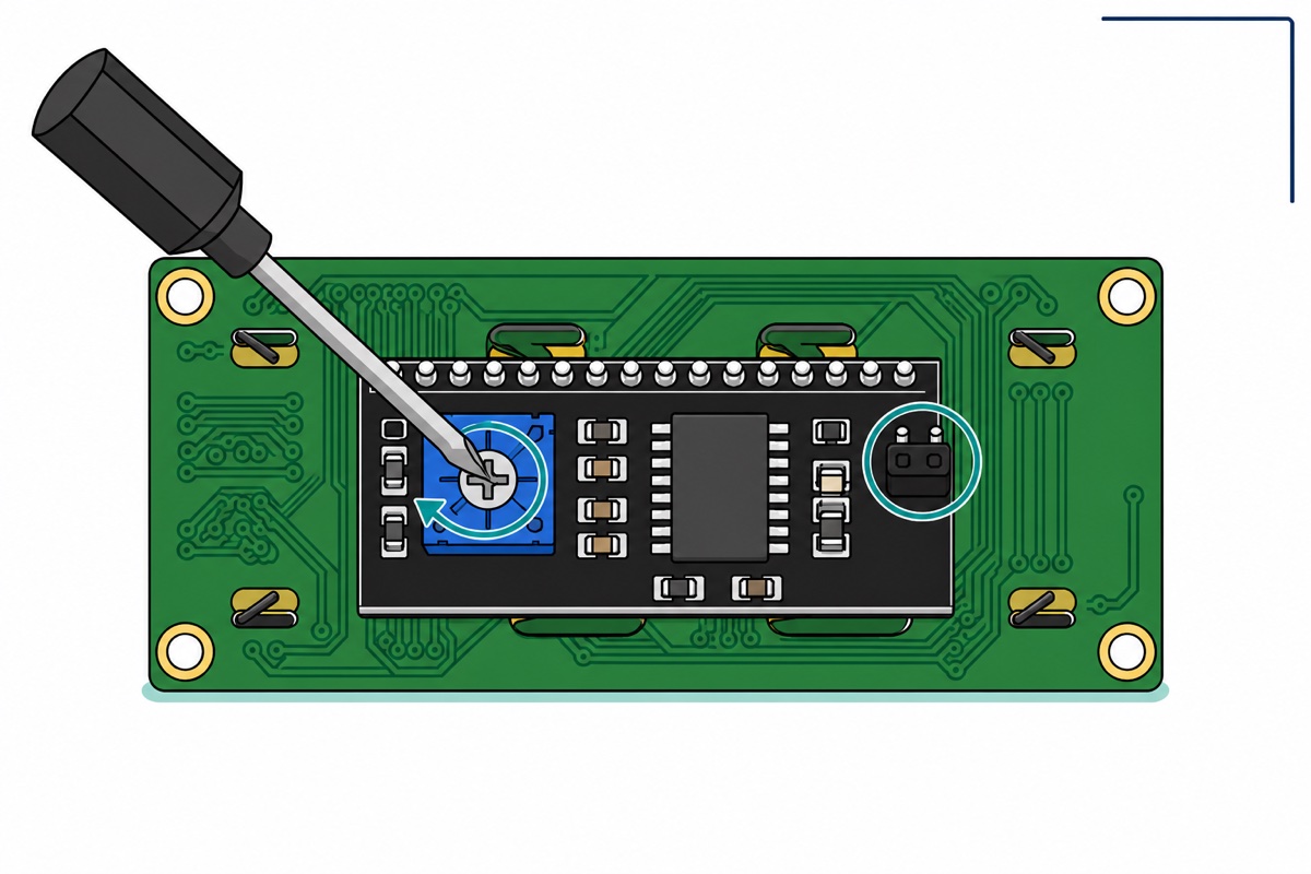
The LCD1602’s contrast and backlight are two independent circuits, and mixing them up is behind almost every blank-screen message we get. The backlight is just an LED behind the glass, fed through the removable black jumper on the backpack — it decides whether the screen glows. Contrast is the blue trimmer: it sets the drive voltage on the LCD’s VO pin, which controls how strongly the liquid crystal segments darken — it decides whether characters are visible. A glowing screen with no text usually has a contrast problem, not a data problem.
So make the trimmer your first stop: power the display and turn it slowly with a small screwdriver until characters appear crisp. No sketch loaded yet? Set it where the top row of faint blocks just becomes visible — that is the same sweet spot. Too far one way and the text fades to nothing; too far the other and every character cell fills into a solid block. Set it once and it holds its setting — it is a screw, not a knob that drifts.
When the trimmer is not the answer, the symptom names the cause:
| What you see | Most likely cause | The fix |
|---|---|---|
| Backlight glows, nothing else | Contrast too low, or wrong I2C address | Turn the blue trimmer; if still blank, run the scanner |
| One row of solid blocks | Powered but never initialised | Wrong address, or the sketch never ran lcd.init() — scan, then check the constructor |
| Random garbled characters | Loose SDA/SCL wire, or wrong address | Re-seat the four jumpers, re-scan, restart the board |
| No glow at all | Backlight jumper missing, or no power | Refit the black jumper cap; check GND and VCC |
The one-row-of-blocks case earns a word of mechanism: those blocks are what an HD44780 shows when it has power and contrast but has never received its initialisation sequence — the display is telling you “I am alive, nobody has spoken to me”. That is a software or address problem, never a broken screen.
Common mistakes we see from real customers
“This lcd is already soldered with i2c chip?” — For the +I2C variants, yes: the backpack ships soldered on, and the four-pin header is the only connection you make. If you are ever unsure which version is in your hand, flip it over — the black board on the back is the I2C interface.
“lcd1602 + I2C last time brough with u need install what library ah” — LiquidCrystal I2C by Frank de Brabander, from Library Manager. The plain LiquidCrystal library that comes with the IDE is for the bare parallel version — it compiles happily but cannot reach a display that hangs off the I2C bus, so the screen stays blank.
“i cant change the address of the lcd” — The address is not set in code, so no sketch can change it: it lives in the backpack’s hardware. What you can do is read it (the scanner) or move it (bridge the A0–A2 solder pads to pull address bits low). For a single display, just put whatever the scanner prints into the constructor and it will work.
Turning the wrong control for the symptom. Glow is the backlight jumper’s job; visibility is the contrast trimmer’s. Match the fix to the symptom table above before touching either.
FAQ
What I2C address is my LCD1602?
Either 0x27 or 0x3F, depending on which expander chip your backpack’s batch carries — PCF8574 modules ship at 0x27, PCF8574A at 0x3F. Run the I2C scanner sketch above and use the address it prints; guessing has a coin-flip failure rate.
Can I use the same code for the LCD2004?
Yes. The 20×4 module uses the same backpack, the same wiring and the same library — change the constructor to LiquidCrystal_I2C lcd(0x27, 20, 4); and everything else carries over unchanged.
Why does my LCD show one row of white blocks?
The display has power and contrast but was never initialised. Usually the sketch is talking to the wrong I2C address, so the init sequence never arrives — run the scanner and fix the constructor. If the address checks out, make sure lcd.init() is actually in setup().
Do I need a breadboard or soldering iron for this build?
Neither. The backpack arrives soldered to the display, its header pins are male, the jumper wires are male-to-female, and the Uno’s headers are female sockets — every connection in the chain simply plugs together.
Can I connect two LCDs to one Arduino?
Yes — that is what the A0–A2 pads are for. Bridge a pad on the second backpack so it answers at a different address, then create two LiquidCrystal_I2C objects, one per address. Both displays share the same A4/A5 wires.
Once the display prints reliably, it becomes the readout for almost anything: our DS3231 digital clock puts a live time on this exact screen, and the keypad password lock hangs its display off the same A4/A5 I2C bus you wired here. Scan first, wire four pins, and the rest is just lcd.print().
Last updated August 2026. Stuck? Chat with us on WhatsApp.
