

Tutorials
Arduino Joystick Module: X/Y Code and a Servo Pan-Tilt
Aug
An analog joystick is two potentiometers at right angles plus a pushbutton, so you read it with analogRead() on two analog pins — but the one-liner everyone writes first, servo.write(map(analogRead(A0),0,1023,0,180)), gives a pan-tilt that creeps and snaps back to centre. Fix it by measuring where your stick really rests, and by letting displacement set speed, not angle.
What do you need to build a joystick-controlled pan-tilt?
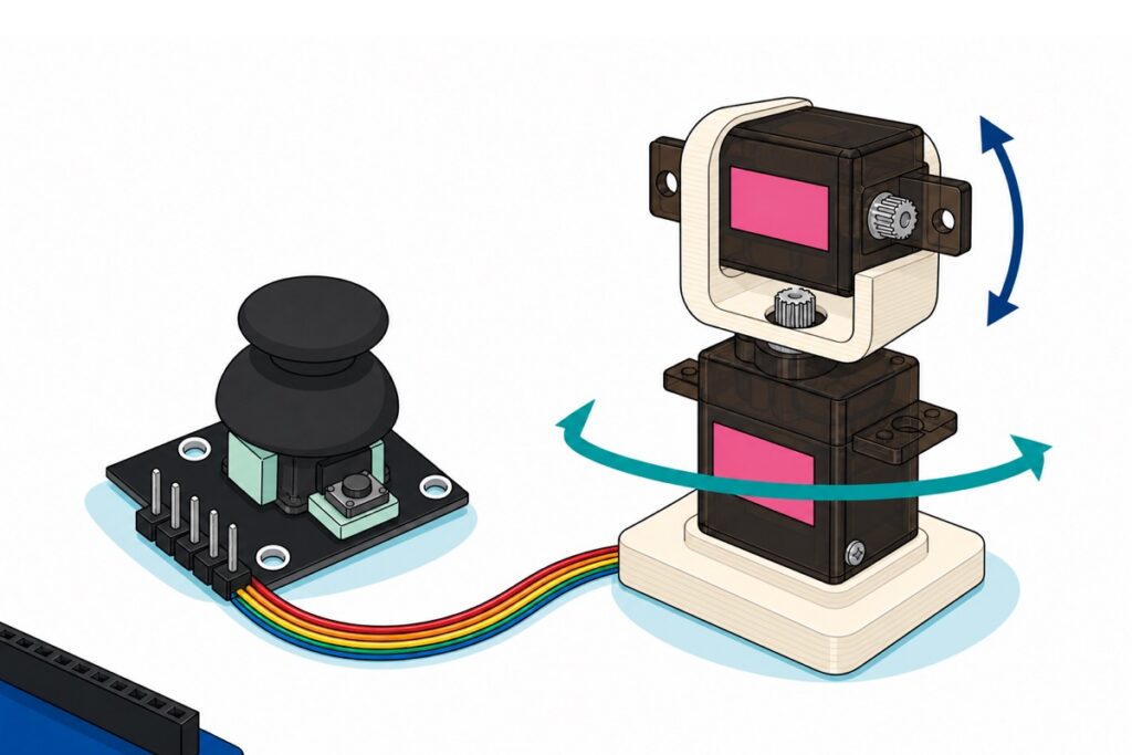
The HW-504 joystick module is a black board with a matte-black thumb cap, two mint-green potentiometers under the gimbal and a straight five-pin male header. Two TowerPro MG90S micro servos give pan and tilt; they arrive as the motor and its lead, so the bracket is part of the build.
Parts list — analog joystick and two MG90S servos on an Arduino Uno pan-tilt
 Joystick Module X Y Z axis 5 Pin Analog Joy Stick Controller for Arduino Robotic
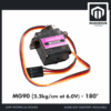 SG90 MG90 Tower Pro Micro Servo Motor 9g 180 360 Servo Motor for Arduino Robotic - MG90- 180°
 Arduino Uno Compatible SMD UNO R3 with Type B Cable - ATMEGA328P with CH340G-Microcontroller Project
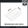 MB102 Breadboard 170 400 830 Holes Breadboard Donut Board Arduino Prototype Multi Color - BREADBOARD (400 HOLES)
 40pcs Dupont Wire 10cm 20cm 30cm for Breadboard DIY Experiment Jumper Wire Breadboard wire - DUPONT WIRE M-M 20CM
 40pcs Dupont Wire 10cm 20cm 30cm for Breadboard DIY Experiment Jumper Wire Breadboard wire - DUPONT WIRE M-F 20CM
Optional — separate servo power and the USB lead
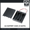 AA Battery Holder with Cover On/Off Switch 2/3/4 Slots Battery AA Holder Red/Black Wire - AA BATTERY CASE (4S)
 Data Cable Type-A Type-C MicroUSB Type-B 0.5m 1m 30cm 0.3m 100cm Data Transfer Upload Code - TYPE-A TO TYPE-B (1.0M)
The 4xAA holder is the fix for two servos browning out a USB-powered Uno: four cells in series give 6 V nominal, right inside the MG90S 4.8–6 V rating, and it feeds the servos only. The Uno's socket takes a full-size USB-B (printer-style) plug — add one if that square shape is not already in your drawer.
The two jumper packs are not redundant: the connectors face opposite ways. The joystick presents male pins, so it takes the female end of a male-to-female jumper to reach the Uno and the breadboard. Each servo lead ends in a three-way female socket, so it takes a male-to-male jumper — as do the two feeds from the Uno to the breadboard rails. A joystick keypad shield or dual-joystick shield skips the wiring entirely; the FT232 Uno suits a PC that fights CH340 drivers.
How does an analog joystick module actually work?
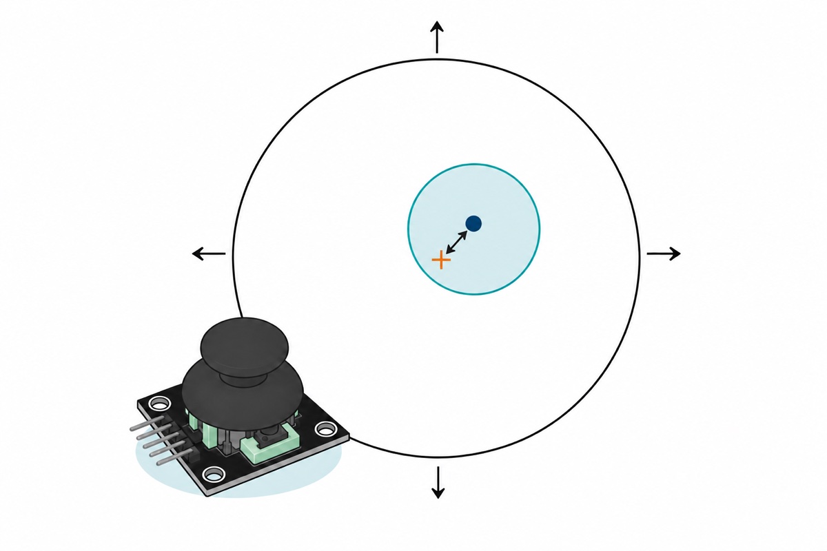
The HW-504’s two potentiometers are wired as voltage dividers across the same +5 V and GND you feed the module, one turned by each axis of the gimbal. Each wiper swings from near 0 V to near 5 V across the stick’s travel, and the ATmega328P’s 10-bit ADC turns that into 0–1023 — about 4.9 mV per count.
The pushbutton is a plain tactile switch between the SW pin and GND with no pull-up resistor on the module, so left alone that pin floats and reads noise. pinMode(PIN_SW, INPUT_PULLUP) switches in the ATmega328P’s own 20–50 kΩ pull-up: the pin then idles HIGH and a press pulls it LOW.
The spring returns the stick to near the electrical centre, not to it: moulding tolerance in the yoke and in the pot track put a rested stick anywhere from the high 490s to the low 530s, differently on each axis and every module. A stick that rests at 507 is fine. Assuming 512 is not.
How do you wire the joystick and two servos to an Uno?
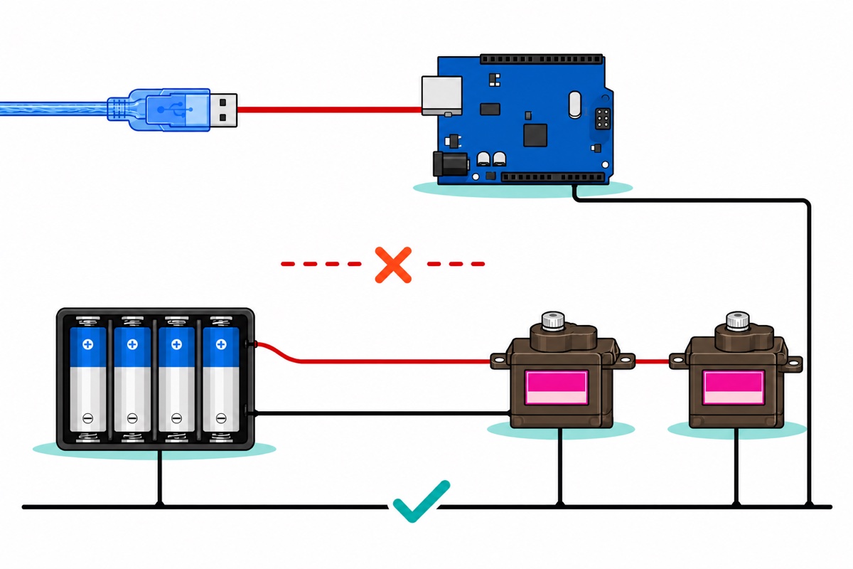
The Uno has one 5 V socket and this build needs more taps, so the breadboard’s rails fan it out. Feed them from the Uno first. Check the joystick’s silkscreen before you count pins: it reads GND, +5V, VRx, VRy, SW — ground first, not the VCC-first order most modules use.
| From | To | Why |
|---|---|---|
Uno 5V and GND |
Near-side + and − rails |
Two male-to-male jumpers. One socket becomes a whole rail |
Joystick +5V, GND |
Near-side + and − rails |
Powers both dividers from the Uno’s 5 V. A 6 V feed here would push the wiper voltages above the ADC’s own reference |
Joystick VRx, VRy |
A0, A1 |
The two wiper voltages the ADC reads |
Joystick SW |
D2 |
Switch to GND; the sketch enables the internal pull-up |
| Pan servo orange | D9 |
Signal only — a 1–2 ms pulse every 20 ms |
| Tilt servo orange | D10 |
Same, second channel |
| Both servo brown | Far-side − rail |
Keeps servo return current off the joystick’s ground |
| Both servo red | Far-side + rail |
Fed by the battery, never by the Uno — see the power section |
Near-side − rail |
Far-side − rail |
Common ground. One jumper, and the only wire between the two supplies |
Keep the two supplies on opposite edges of the board. The 400-point breadboard runs its own + and − strip down each long side, so the Uno feeds one pair and the battery the other, and the jumper tying the two − strips is the only wire that crosses between them. Bridge the two + strips instead and 6 V lands on the Uno’s 5 V pin — the connection this build must never make. Without a battery that bridge is how the servos run off the Uno, which is a brief unloaded test only.
Pins 9 and 10 are a sensible default, not a requirement. The Servo library claims Timer1 at the first attach() whichever pins you use, and Timer1 is the hardware that generates PWM on pins 9 and 10 — so analogWrite() there stops working either way. Pins 3, 5, 6 and 11 keep theirs.
Why does the obvious one-line map() sketch drift and twitch?
The one-line map() sketch is aimed at the wrong number. A joystick resting at 507 maps to 89°, not 90°, so the mount sits a degree off. Worse, position mode makes the mount follow the stick absolutely: let go, the spring returns the stick to centre, and your aimed camera swings back to the middle of the room. That is the wrong control law for a mount, not a bug to tune out.
Its dead zone is zero. The ADC reading wanders a count or two, and map() spreads 1023 counts over 180°, so 5.7 counts make a degree. A degree of command is about 10 µs of pulse and the MG90S dead band is 5 µs — so the gear train can hunt on a stick nobody is touching.
Its ground moves. The obvious suspect is innocent: the ADC measures against the same 5 V rail that powers the potentiometers, so when that rail sags the wiper voltage sags in proportion and the reading does not change. What does not cancel is return current. Two servos pull hundreds of milliamps back through the shared ground jumper and breadboard contacts, and 0.2 Ω of that path turns 300 mA into 60 mV of ground offset — about 12 ADC counts, appearing and vanishing as the servos move.
How do you make the stick control speed instead of angle?
Velocity control is one small change to the joystick sketch. Instead of angle = f(stick) you write angle = angle + f(stick): the stick sets degrees added per frame, releasing it adds zero, and the mount stays where you steered it. It also does for free the smoothing people bolt on afterwards: the commanded angle can move by at most MAX_STEP per frame, so no reading — noisy, glitched or otherwise — can shift the mount faster than that. An averaging filter attacks the noise; a rate limit makes the noise harmless whatever its size.
The numbers follow from the servo. It refreshes every 20 ms, so a shorter frame commands motion it cannot act on. At a full-stick step of 1.5° per frame the mount sweeps 75°/s and crosses the sketch’s 10°–170° pan span in a little over two seconds — deliberate and filmable. The MG90S is rated 0.08 s per 60°, or 750°/s, so a 1.5° step takes it about two milliseconds — done, and idle for the rest of the frame. The servo is never chasing the command, which is why the sweep looks smooth rather than jerky. A 60-count dead zone is five times the ground-offset budget above and still leaves 88% of each direction’s travel usable.
/*
  Analog joystick (HW-504) -> two MG90S servos, pan-tilt with VELOCITY control.
  Library: Servo (bundled with the Arduino IDE).

  Joystick GND -> rail GND    +5V -> rail 5V
  Joystick VRx -> A0    VRy -> A1    SW -> D2 (internal pull-up)
  Servo orange -> D9 (pan) and D10 (tilt)
  Servo red -> 6V battery +    Servo brown -> GND, shared with the Uno

  Stick DISPLACEMENT sets the SPEED of the angle change, not the angle itself.
  Let go and the mount stays put. Hold the button to walk it back to centre.
*/
#include <Servo.h>

const uint8_t PIN_VRX  = A0;
const uint8_t PIN_VRY  = A1;
const uint8_t PIN_SW   = 2;
const uint8_t PIN_PAN  = 9;    // Timer1 pins - see the article
const uint8_t PIN_TILT = 10;

const int      DEADZONE = 60;    // ADC counts either side of the measured rest
const float    MAX_STEP = 1.5;   // degrees moved per 20 ms frame at full stick
const uint16_t FRAME_MS = 20;    // one servo refresh period

const int PAN_MIN  = 10, PAN_MAX  = 170;   // keep away from the mechanical stops
const int TILT_MIN = 30, TILT_MAX = 150;

Servo pan, tilt;

int   restX, restY;                        // measured at power-up, not assumed 512
float panAngle = 90.0, tiltAngle = 90.0;
uint32_t lastFrame = 0, lastReport = 0;

// Discard the first conversion after the mux moves, then average eight.
int readAxis(uint8_t pin) {
  analogRead(pin);
  long sum = 0;
  for (uint8_t i = 0; i < 8; i++) sum += analogRead(pin);
  return (int)(sum / 8);
}

// Stick offset -> degrees per frame. Zero inside the dead zone, MAX_STEP at the stop.
float axisRate(int raw, int rest) {
  int offset = raw - rest;
  if (offset > -DEADZONE && offset < DEADZONE) return 0.0;

  int span, past;
  if (offset > 0) { past = offset - DEADZONE; span = 1023 - rest - DEADZONE; }
  else            { past = offset + DEADZONE; span = rest - DEADZONE;        }
  if (span < 1) span = 1;

  float k = (float)past / (float)span;
  if (k >  1.0) k =  1.0;
  if (k < -1.0) k = -1.0;
  return k * MAX_STEP;
}

void setup() {
  Serial.begin(115200);
  pinMode(PIN_SW, INPUT_PULLUP);   // the module carries no pull-up of its own

  // CALIBRATION: read where YOUR stick actually rests. Hands off during setup.
  restX = readAxis(PIN_VRX);
  restY = readAxis(PIN_VRY);
  Serial.print(F("rest X = "));    Serial.print(restX);
  Serial.print(F("   rest Y = ")); Serial.print(restY);
  Serial.println(F("   (near 512, but neither will be exactly 512)"));

  pan.attach(PIN_PAN);
  tilt.attach(PIN_TILT);
  pan.write((int)panAngle);
  tilt.write((int)tiltAngle);
}

void loop() {
  if (millis() - lastFrame < FRAME_MS) return;
  lastFrame = millis();

  int x = readAxis(PIN_VRX);
  int y = readAxis(PIN_VRY);

  if (digitalRead(PIN_SW) == LOW) {
    // Button held: walk back to centre at the same rate limit. Never snap.
    panAngle  += constrain(90.0 - panAngle,  -MAX_STEP, MAX_STEP);
    tiltAngle += constrain(90.0 - tiltAngle, -MAX_STEP, MAX_STEP);
  } else {
    panAngle  = constrain(panAngle  - axisRate(x, restX), PAN_MIN,  PAN_MAX);
    tiltAngle = constrain(tiltAngle + axisRate(y, restY), TILT_MIN, TILT_MAX);
  }

  pan.write((int)(panAngle + 0.5));
  tilt.write((int)(tiltAngle + 0.5));

  // Live numbers so you can watch the dead zone do its job.
  if (millis() - lastReport >= 500) {
    lastReport = millis();
    Serial.print(F("X "));       Serial.print(x);
    Serial.print(F("  Y "));     Serial.print(y);
    Serial.print(F("  pan "));   Serial.print((int)panAngle);
    Serial.print(F("  tilt "));  Serial.println((int)tiltAngle);
  }
}
On an Uno this compiles to 6,030 bytes of flash — 18% of the 32 KB — and 252 bytes of RAM. The Serial Monitor at 115200 prints your module’s rest values on the first line. Widen DEADZONE if the mount still creeps with your hands off the stick; flip the sign on an axisRate call if that axis steers backwards, or exchange PIN_VRX and PIN_VRY if a quarter-turn mounting swapped the axes.
Can an Arduino’s 5 V pin run two MG90S servos?
The MG90S is rated 4.8–6 V and draws about 10 mA idle, 120–250 mA moving and around 700 mA at stall, a bench figure rather than a TowerPro rating. Two moving together is 240–500 mA, the Uno wants another 40–50 mA, and the USB path is guarded by a resettable polyfuse that breaks the connection above 500 mA. The build sits on that line rather than inside it, which is why it works until the tilt servo takes load and the board resets.
Give the servos their own supply. Four AA cells in a switched holder are 6.0 V nominal in series, inside the MG90S rating, and a fresh alkaline set at about 6.4 V settles under load. Its red lead goes to the far-side + rail and its black to the far-side − rail — never to the Uno’s 5 V pin. That pin is the regulator’s output, not an input, and while the board is on USB it sits on the same rail the USB port feeds, so 6 V pushed in there travels backwards through the regulator and up the cable towards your laptop’s port. Twist the holder’s bare lead ends tightly before they meet a breadboard hole.
What do you mount the servos on?
The MG90S ships as the motor and its lead, which makes the bracket a design decision. In a pan-tilt the lower servo carries the upper one plus whatever sits on top, so its load is a weight on a lever arm. A tilt servo and a light bracket — 40 g on a 3 cm arm — is about 0.12 kg·cm against the MG90S’s 2.2 kg·cm at 6 V. Put a 200 g phone on a 5 cm arm and you are asking for 1.0 kg·cm: still inside rating on paper. What strips a nylon gear, though, is rarely the steady load — it is the shock of a knock or a drive into the stop, arriving at one tooth at once. That is the case for metal gears on the axis carrying the weight. Our servo comparison guide covers the rest of that choice.
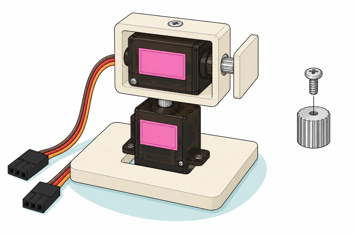
The bracket is print-one or make-one. The MG90S output is a 21-tooth metal spline about 4.7 mm across with a small screw hole down its centre, so a printed socket press-fits over the spline and an M2 self-tapping screw into that hole stops it climbing off under load — Smith3D stocks the filament and printers.
Fit the brackets with the servos already centred. A shaft sits wherever it was last left, so run the sketch first and let setup() drive both servos to 90°, then press each bracket straight down onto its spline — straight down, not turned, because the servo is holding that angle. Fit one to an uncentred shaft and the mount’s mechanical middle lands anywhere: the stick runs out of sweep one way and hits the stop the other.
For a bench demo, stiff card and hot glue work; nothing in the sketch cares — and once the mount holds still, an ESP32-CAM is the obvious thing to put on top. This assembly video shows the coupling in the hand:
Common mistakes we see from real customers
Powering both servos from the Uno, then blaming the joystick. Readings jump, the mount stutters, the board restarts — all three are the current budget above, not a faulty stick.
Calibrating with a hand on the stick. The sketch measures the rest values once, in setup(), and every later reading is an offset from them. Hold the stick while the board boots — or reset it mid-steer — and the mount inherits a false centre, so it creeps with the stick released: exactly the drift the calibration exists to remove. Let go, reset, and watch the two rest numbers settle to the same pair.
Fighting the servo mechanically. Writing 0° or 180° into a servo whose bracket stops it earlier makes it push against the stop and sit there drawing stall current until something gives — that is what PAN_MIN and TILT_MAX are for. For the same reason, never twist a powered servo’s output by hand.
FAQ
Why does my Arduino joystick read 512 instead of 0?
Because it is working. Mid-travel puts each wiper halfway along its track, so it delivers half of 5 V — roughly 512 of the ADC’s 1023 counts.
Why won’t my joystick read exactly 512 at rest?
Mechanical tolerance in the gimbal and pot track. High 490s to low 530s is normal, and the two axes differ. Measure both at startup.
Can I run two servos from the Arduino’s 5 V pin?
Only for a brief unloaded test. Two MG90S moving together draw 240–500 mA and the Uno’s USB supply trips above 500 mA. Four AA cells, grounds tied, is the reliable arrangement.
Why does the Servo library break analogWrite on pins 9 and 10?
It takes over Timer1, the hardware that produces PWM on those two pins, at the first attach() — whichever pins the servos use. Pins 3, 5, 6 and 11 keep their PWM.
Do I need a joystick shield instead of the module?
No — both are potentiometers on analog pins, so the code is identical. A shield saves the wiring; the bare module can sit in a handheld enclosure.
Last updated August 2026. Stuck? Chat with us on WhatsApp.
