

Tutorials
Bluetooth RC Car with Arduino and HC-05: Code, App, Wiring
Aug
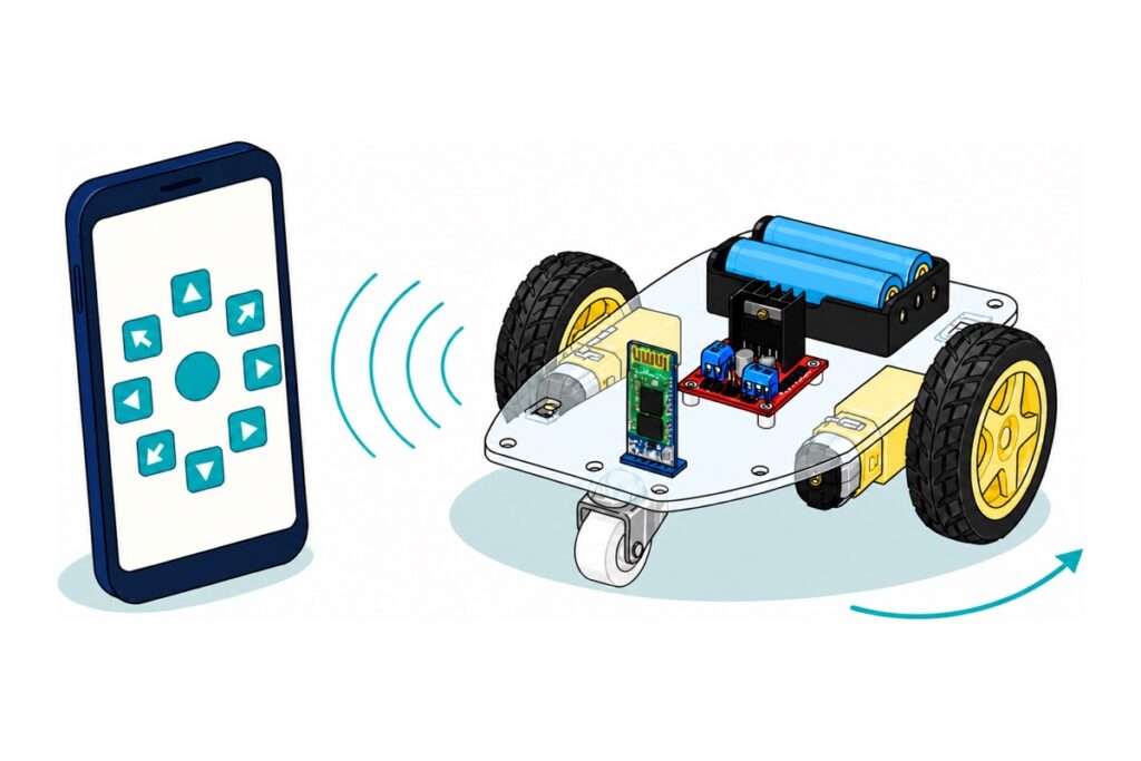
A Bluetooth RC car is a 2WD chassis, an L298N driver and an HC-05 module that hands your phone’s button presses to an Arduino. Every button in a free RC-controller app sends one ASCII character — “F” for forward, “S” for stop — and the sketch is a switch-case that turns each character into an H-bridge state. Understand that one idea and any Bluetooth app will drive your car — from an Android phone, because the HC-05 speaks Bluetooth Classic and iOS keeps that closed to ordinary apps.
What parts does a Bluetooth RC car need?
The 2WD chassis kit supplies the mechanics — acrylic plate, two TT gear motors, wheels, a caster, screws and a rocker switch. The HC-05 is the only part that separates this build from our obstacle-avoiding car: same chassis, same driver, same battery, a different thing telling it where to go.
Parts list — Bluetooth RC car with Arduino and HC-05
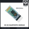 Wireless Bluetooth Module HC-05 HC-06 Master Slave Bluetooth Module HC05 HC06 - HC-05 BLUETOOTH MODULE
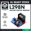 L298N Motor Driver Module Arduino Compatible Dual H Bridge Dual DC Motor Control Arduino Robotic Car
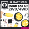 2WD 4WD Smart Car Chassis Single Layer Acrylic Arduino Smart Car Chassis Kit With Motor - 2WD CAR KIT
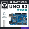 Arduino Compatible UNO R3 FT232 Development Board Arduino Compatible CH340 Alternative
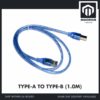 Data Cable Type-A Type-C MicroUSB Type-B 0.5m 1m 30cm 0.3m 100cm Data Transfer Upload Code - TYPE-A TO TYPE-B (1.0M)
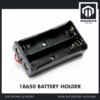 18650 Battery Holder 1/2/3/4 Slot 3.7V Battery Cell Housing Battery Case Battery Casing - 18650 BATTERY HOLDER (2)
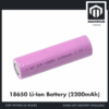 3.7V 18650 Battery Rechargeable Li-Ion Battery 1200mAh 2200mAh 3200mAh Flat Top - 18650 Li-Ion Battery (2200mAh)
 40pcs Dupont Wire 10cm 20cm 30cm for Breadboard DIY Experiment Jumper Wire Breadboard wire - DUPONT WIRE M-F 20CM
 40pcs Dupont Wire 10cm 20cm 30cm for Breadboard DIY Experiment Jumper Wire Breadboard wire - DUPONT WIRE M-M 20CM
Parts list
 TP4056 18650 Battery Charger Module Lithium Ion Battery Li-ion Battery Charger Type C Micro USB - TP4056 CHARGER (TYPEC)
 Soldering Service for Circuit Boards & Electronics - 5 Pins Soldering Service
 400 pcs 1/4W Resistor Pack Resistor Kit 20 Common Value with 20 each
The 4WD chassis is the alternative lane and runs this exact sketch, with each side's two motors wired in parallel into one L298N channel. The TP4056 is a single-cell charger, so it recharges the two 18650 cells one at a time and out of the holder, and it must never be connected across the 7.4 V pack as a whole. The 5-pin soldering service covers the four motor-tab joints if you would rather not solder, and the resistor pack covers the divider pair if you later add the return wire described below, where any 1:2 ratio works: 1k with 2k, or 10k with 20k.
Wire gender decides whether your first order is usable. The HC-05’s six pins are a right-angle male header and the L298N‘s IN1–IN4 are male pins too, while the Uno‘s edges are female sockets — so every signal wire is male-to-female. The power runs are the exception: a bare male pin clamps into an L298N screw terminal and the far end plugs into a female Uno socket, which is the male-to-male pack. The battery holder‘s tinned leads go straight into screw terminals, so nothing here needs a breadboard — keep stiff breadboard wire for bench work. The Uno programs over full-size USB-B, so it needs the A-to-B cable. One habit to form before the first connection: the HC-05 carries its pin names on the underside of the board rather than the top, so turn the module over and read them. VCC and GND sit side by side on that row, and reversing those two is the mistake that ends a module.
The TT motors are the one soldered job — bare tabs on the rear end cap, loose wire pairs, four joints. Our soldering guide has the technique, or the 5-pin soldering service covers exactly those four.
Assemble the chassis before any wiring. The acrylic plate and the small motor tabs arrive under a kraft-brown protective film that makes them look like cardboard — lift a corner and peel both faces first, or a finished car still looks unfinished. Bolt one motor to each side of the plate with those tabs and the long screws, press a wheel onto each shaft, fit the caster under the opposite end, and keep the top of the deck clear for the Uno, the driver and the battery holder.
How does a phone app actually control the car?
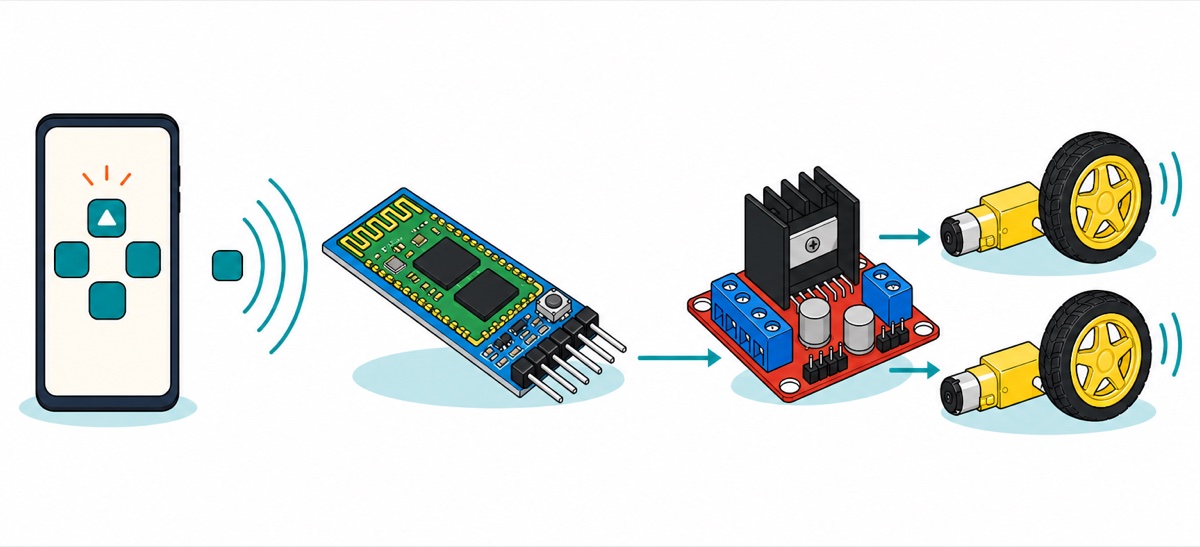
A Bluetooth RC-controller app is not doing anything clever. Once paired, the HC-05 presents itself as a plain serial port, and the app is a keyboard with pictures on the keys: press the up arrow and it sends the single byte F; release it and it sends S. Nothing else crosses the link — no handshake, no packet format, no protocol library to install.
That is also why we point you at a search rather than at one app. On the Play Store, Arduino Bluetooth RC car and Bluetooth RC controller each return a shelf of free controllers, and the one you want says it works with HC-05 or HC-06 — an app written for Bluetooth Low Energy cannot see a Classic module at all, which is the single most common reason a correctly wired car never responds. The name is not the specification either: several unrelated apps ship under near-identical titles and send different characters for the same arrow. So pick one, then find out what it actually sends. Nothing here needs an APK from a download site, and a controller asking for permissions beyond Bluetooth is asking for more than the job requires.
So never trust a command table you read somewhere, including this one — app versions differ, and your own phone will tell you in a minute. For this test wire only the HC-05’s VCC, GND and TXD to the Uno’s 5 V, GND and D2, and leave the battery switch off. The Uno’s 5 V pin is the regulated rail itself rather than an input ahead of the regulator, so anything you feed into it sits directly across whatever the USB port is supplying — USB and the L298N’s 5 V output must never be connected at the same time. Upload this, open the Serial Monitor at 9600 baud, connect the app, and press each button in turn:
// Step 1: find out what YOUR app actually sends.
// Upload this, open Serial Monitor at 9600, connect the app, press buttons.
#include <SoftwareSerial.h>
SoftwareSerial bt(2, 3);   // 2 = Uno RX, wired to HC-05 TXD. 3 stays unwired.

void setup() {
  Serial.begin(9600);
  bt.begin(9600);
  Serial.println(F("Press a button in the app..."));
}

void loop() {
  if (bt.available()) {
    char c = bt.read();
    Serial.print(c);
    Serial.print(F("  (byte "));
    Serial.print((int)c);   // prints the number too, for invisible characters
    Serial.println(F(")"));
  }
}
Most free RC-controller apps land on the same set, which the main sketch below expects:
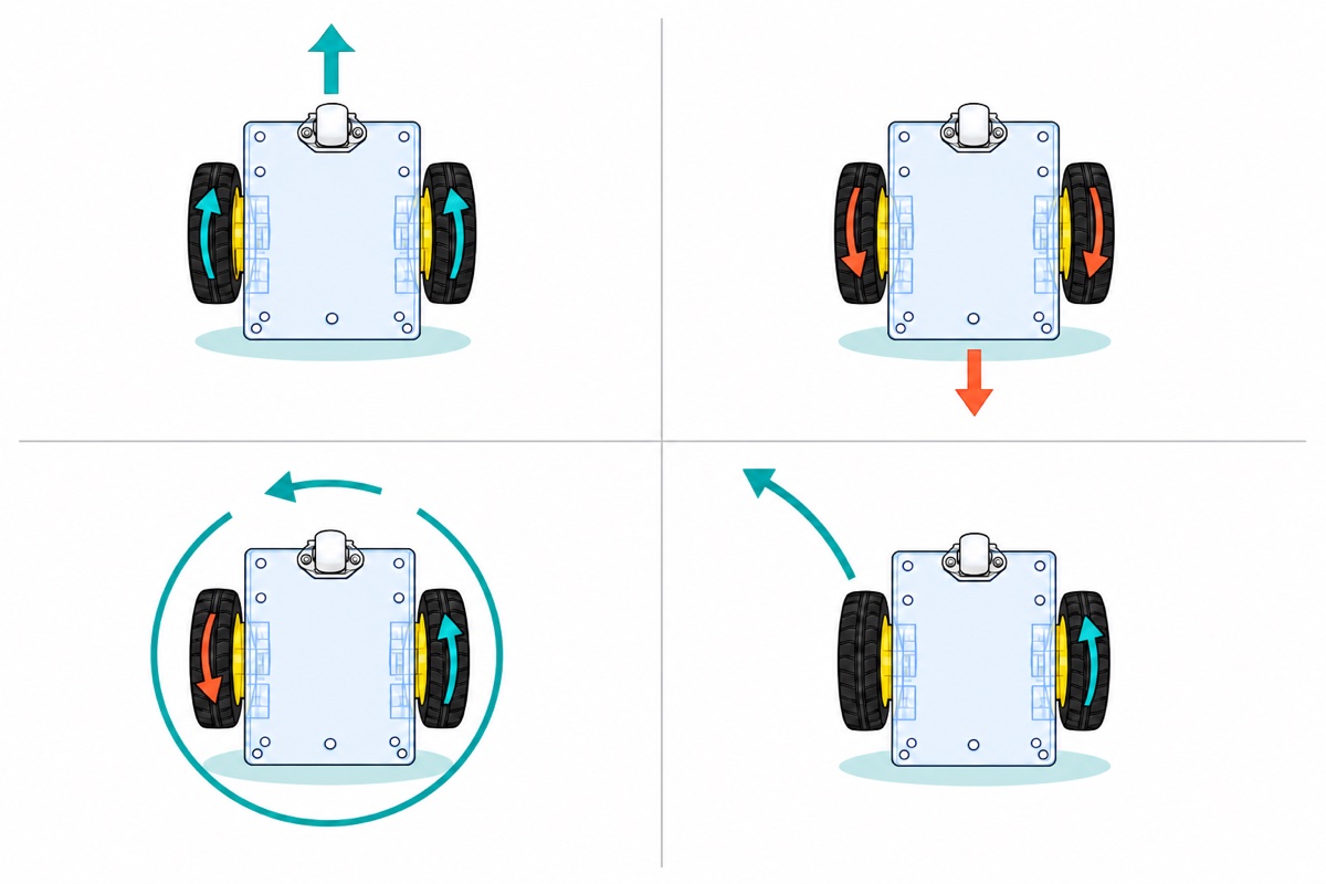
| App button | Character sent | What the sketch makes the car do |
|---|---|---|
| Forward / Reverse | F / B |
Both motors the same way |
| Left / Right | L / R |
Motors in opposite directions — spins on the spot |
| Four diagonals | G I H J |
One wheel driven, one free — a wide arc |
| Button released | S |
Both enables to zero |
| Speed slider | 0–9, q |
Sets the PWM value used by the next move |
| Lights, horn, anything else | other letters | Unrecognised, so the sketch stops the car — give a horn or lights button its own empty case if that gets in your way |
Note what that implies: the car holds its last order until a new one arrives, so a phone that walks out of range mid-throttle leaves it driving. The HC-05’s link reaches roughly ten metres in open space and noticeably less through a wall or a body, which is closer than most people assume before they try it. The chassis kit’s rocker switch sits in the battery lead — that is your kill switch, and it belongs within reach.
How do you pair the HC-05 with an Android phone?
The HC-05 is a Bluetooth Classic device using the Serial Port Profile, so it appears in Android’s ordinary Bluetooth settings rather than inside the app — and, because iOS does not open Classic serial ports to ordinary apps, this is an Android-only route. Power the car, open Settings, pair with the device named HC-05, and enter the PIN 1234 — a few batches ship with 0000 instead. Only then open the RC app and pick the module from its device list.
Pairing and connecting are different states, and confusing them is the commonest reason a finished car sits still. Android remembers the pairing forever; the app opens the data connection afresh each time. The module shows you which state it is in — its LED blinks about twice a second while waiting, and settles to a slow double-blink once an app holds the port open. Our HC-05 phone-control guide covers renaming and AT mode in full.
The HC-06 substitutes here without changing anything: slave-only costs nothing in a car that never initiates a connection. Seeing the pairing and first drive end to end helps:
Does this build need a voltage divider on the HC-05?
No — the HC-05 in a drive-only car needs no resistors at all. The reason matters more than the answer, because half the wiring diagrams online add two that this build never uses.
The HC-05’s radio core runs at 3.3 V, so its TXD output swings between 0 and 3.3 V and its RXD input is not 5 V tolerant. Those are two separate wires with two separate problems. In the direction that matters here, 3.3 V has to be read reliably as a logic high by the Uno’s ATmega328P, whose datasheet guarantees a high above 0.6 × VCC. On a 5 V board that threshold is 3.0 V, and 3.3 V clears it — comfortably enough that this is a specification, not a lucky margin.
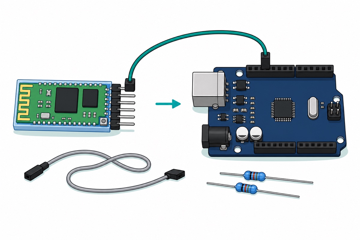
A drive-only car never sends anything back to the phone, so the Uno’s transmit pin has no job. Leave it unwired and the 5 V-into-3.3 V problem never exists: power, ground, and one signal wire. The divider becomes genuinely necessary the moment you want the car to talk back — battery voltage on the app’s terminal screen, sensor readings, or an AT session to rename the module. Then run Uno D3 through a 1 kΩ resistor to RXD with a 2 kΩ from RXD down to GND: the pair splits 5 V in the ratio 2/(1+2), which is 3.3 V, and the sketch’s reserved BT_TX_PIN starts earning its keep.
Do not move the module to pins 0 and 1 instead. Those are the Uno’s hardware serial pins, shared with the USB chip, so a connected HC-05 fights every upload — the classic stk500_recv(): programmer is not responding failure that has people returning good boards. SoftwareSerial on D2 keeps the two conversations apart.
How do you wire the driver, the module and the battery?
The two 18650 cells start one loop with two taps. They sit head to tail in the 2-slot holder, which is series wiring: 7.4 V nominal, 8.4 V charged. That pack feeds the L298N’s +12V terminal, where the bridge keeps roughly 1.8 V for itself and passes about 5.6 V to motors rated 3–6 V, while the board’s own regulator turns the same input into a clean 5 V for the Uno and the HC-05. The kit’s 4×AA holder cannot do this — 6 V minus the bridge leaves 4.2 V and a car that crawls — and a 4-slot 18650 holder is worse, because multi-slot holders series their cells too and four would hand the bridge 14.8 V, about 13 V of it reaching a 6 V motor. The obstacle-avoiding car works that arithmetic through in full.
Leave the small 5V-EN jumper fitted, which is what connects that regulator to the input, and pull the two black caps off ENA and ENB — as shipped they tie both enables high, so the car has exactly one speed no matter what the app’s slider does.
| From | To | Why |
|---|---|---|
| Holder red lead, through the kit’s rocker switch | L298N +12V screw terminal | The 7.4 V pack feeds the bridge and the onboard 5 V regulator |
| Holder black lead | L298N GND (middle screw) | Return path for the motor current |
| L298N +5V screw terminal | Uno 5V pin | Runs the Uno and the module — no second battery |
| L298N GND | Uno GND | Without a shared ground the IN pins have no reference |
| L298N OUT1 / OUT2 | Left motor’s two wires | Swap them if that wheel runs backwards — no code change |
| L298N OUT3 / OUT4 | Right motor’s two wires | Same rule for the other side |
| L298N IN1 / IN2 | Uno D9 / D8 | One high and one low picks the left motor’s direction |
| L298N IN3 / IN4 | Uno D7 / D6 | Same pair for the right motor |
| L298N ENA / ENB (caps removed) | Uno D10 / D11 | PWM speed for each side |
| HC-05 VCC / GND | Uno 5V / GND | The module’s regulator accepts 3.6–6 V; 5 V is its normal supply |
| HC-05 TXD | Uno D2 | The one signal wire: the module talks, the Uno listens |
| HC-05 RXD, EN, STATE | Nothing | Unused in a drive-only car |
The Arduino code: one character in, one H-bridge state out
Only SoftwareSerial is needed, and it ships with the Arduino IDE. Select Arduino Uno, upload over the A-to-B cable, then unplug USB before switching the pack on — and switch the pack off again before USB goes back in, for the same reason. It compiles to 3,884 bytes, about 12% of the Uno’s flash. It keeps printing every character it receives to the Serial Monitor, so a stubborn car can be diagnosed on the bench with its wheels in the air.
// Bluetooth RC car: Arduino Uno + HC-05 + L298N + 2WD chassis.
// The phone app is a keyboard. Every button sends ONE ASCII character,
// and this sketch is the switch-case that turns each character into an
// H-bridge state. Change the letters to match whatever app you use.

#include <SoftwareSerial.h>

// ---- Pins ----
const uint8_t BT_RX_PIN = 2;   // Uno RECEIVES here <- HC-05 TXD
const uint8_t BT_TX_PIN = 3;   // reserved by the library, deliberately NOT wired

const uint8_t ENA_PIN = 10;    // left speed      (PWM)
const uint8_t IN1_PIN = 9;     // left direction
const uint8_t IN2_PIN = 8;
const uint8_t IN3_PIN = 7;     // right direction
const uint8_t IN4_PIN = 6;
const uint8_t ENB_PIN = 11;    // right speed     (PWM)

SoftwareSerial bt(BT_RX_PIN, BT_TX_PIN);

// ---- The numbers you tune ----
// 140 of 255 is roughly the duty a TT motor needs to start moving on a
// 7.4 V pack once the L298N has taken its share. Below it the gearbox
// buzzes instead of turning.
const uint8_t SPEED_FLOOR = 140;
const uint8_t SPEED_TOP   = 250;

// No two TT motors are identical. Raise the trim on the side that
// lags, 5 counts at a time, until the car tracks straight.
const uint8_t TRIM_LEFT  = 0;
const uint8_t TRIM_RIGHT = 0;

uint8_t speedNow = 200;        // changed by the app's speed buttons

// One call sets both sides. A speed of 0 leaves that wheel free to roll,
// which is what makes a gentle arc different from a spin on the spot.
void motors(bool leftFwd, uint8_t leftPwm, bool rightFwd, uint8_t rightPwm) {
  digitalWrite(IN1_PIN, leftFwd  ? HIGH : LOW);
  digitalWrite(IN2_PIN, leftFwd  ? LOW  : HIGH);
  digitalWrite(IN3_PIN, rightFwd ? HIGH : LOW);
  digitalWrite(IN4_PIN, rightFwd ? LOW  : HIGH);

  uint8_t l = (leftPwm  == 0) ? 0 : min(255, leftPwm  + TRIM_LEFT);
  uint8_t r = (rightPwm == 0) ? 0 : min(255, rightPwm + TRIM_RIGHT);
  analogWrite(ENA_PIN, l);
  analogWrite(ENB_PIN, r);
}

void halt() {
  analogWrite(ENA_PIN, 0);
  analogWrite(ENB_PIN, 0);
}

void setup() {
  pinMode(ENA_PIN, OUTPUT);
  pinMode(IN1_PIN, OUTPUT);
  pinMode(IN2_PIN, OUTPUT);
  pinMode(IN3_PIN, OUTPUT);
  pinMode(IN4_PIN, OUTPUT);
  pinMode(ENB_PIN, OUTPUT);
  halt();

  Serial.begin(9600);          // USB window, for watching what arrives
  bt.begin(9600);              // the HC-05's own factory rate
  Serial.println(F("Bluetooth RC car ready."));
}

void loop() {
  if (!bt.available()) {
    return;                    // nothing new: the last order still stands
  }

  char c = bt.read();
  Serial.println(c);           // so you can see exactly what your app sends

  // Some apps end each button with a newline. Ignore it, or the car
  // would stop a millisecond after every command.
  if (c == '\n' || c == '\r') {
    return;
  }

  // Speed buttons: '0' is the slowest useful setting, '9' the fastest,
  // and 'q' is the app's full-speed button.
  if (c >= '0' && c <= '9') {
    speedNow = map(c - '0', 0, 9, SPEED_FLOOR, SPEED_TOP);
    return;                    // speed changes do not restart the motors
  }
  if (c == 'q') {
    speedNow = 255;
    return;
  }

  switch (c) {
    case 'F': motors(true,  speedNow, true,  speedNow); break;  // forward
    case 'B': motors(false, speedNow, false, speedNow); break;  // reverse

    // Opposite directions spin the car on the spot.
    case 'L': motors(false, speedNow, true,  speedNow); break;  // spin left
    case 'R': motors(true,  speedNow, false, speedNow); break;  // spin right

    // One wheel driven, one free: a wide arc instead of a pivot.
    case 'G': motors(true,  0,        true,  speedNow); break;  // forward-left
    case 'I': motors(true,  speedNow, true,  0);        break;  // forward-right
    case 'H': motors(false, 0,        false, speedNow); break;  // back-left
    case 'J': motors(false, speedNow, false, 0);        break;  // back-right

    case 'S': halt(); break;                                    // stop

    // Anything we do not recognise - a lights button, line noise, a
    // character from a different app - means "intent unknown", so stop.
    default:  halt(); break;
  }
}
Why does the speed slider feel dead at the bottom?
Because a low PWM value is not a slow TT motor, it is a stalled one. PWM chops the supply on and off, and the motor responds to the average: at 7.4 V minus the bridge’s 1.8 V share, full duty puts about 5.6 V across the winding, so half duty is roughly 2.8 V. A TT gearbox needs somewhere near 3 V to break its own stiction from rest, which is about 54% duty — that is where SPEED_FLOOR = 140 comes from. Once the car is already rolling, lower values keep it going fine; it is starting that fails, which is why the slider seems to work until you stop.
Curving instead of running straight is mechanical, not a bug: two moulded gear trains never have identical friction, so the same PWM gives slightly different wheel speeds. That is what TRIM_LEFT and TRIM_RIGHT exist for — raise the lagging side five counts at a time until it tracks true. Our L298N speed control guide goes further into PWM on this driver.
Common mistakes we see from real customers
Paired in Android settings, but nothing happens. Pairing only exchanges the PIN; the app still has to open the connection. Select the HC-05 in the RC app’s own device list and watch the module’s LED go from a fast blink to a slow double-blink.
Serial Monitor shows the right letters but the wheels do nothing. Signal and power are separate faults. Check that the L298N’s GND actually reaches the Uno’s GND, and that ENA and ENB are either driven by D10 and D11 or still wearing their jumper caps — with a cap off and no wire on, that enable is a floating logic input, which is neither a dependable on nor a dependable off.
The characters arrive as gibberish. The module and the sketch disagree on baud rate. A module that has been through an AT session can be left at 38400 while bt.begin(9600) keeps reading at 9600, so every byte is sampled at the wrong instants. Either set the sketch to match, or send AT+UART=9600,0,0 in AT mode to put the module back.
It drives fine for twenty minutes, then keeps dropping the connection. The L298N’s 5 V supply is a linear regulator, and a linear regulator needs its input to stay roughly two volts above its output. A charged pack hands it 8.4 V and plenty of room; as the cells empty toward 6 V that room disappears, the 5 V rail sags with them, and the Uno and the HC-05 reset mid-drive while the motors are still turning. Charge the cells before you blame the app, and stop running them below about 3.2 V each — our 18650 charging guide covers doing that safely.
FAQ
What is the default PIN for an HC-05 Bluetooth module?
1234, with 0000 on a few batches. Android asks for it once, at pairing time, in the phone’s own Bluetooth settings rather than inside the RC app.
Do I need a voltage divider for the HC-05 on an RC car?
Not for a drive-only car. Only HC-05 TXD to Uno D2 is wired, and 3.3 V clears the ATmega328P’s 3.0 V input-high threshold. Add the 1 kΩ/2 kΩ divider when you wire Uno D3 to RXD for telemetry or AT commands.
Can I control an HC-05 car from an iPhone?
No. The HC-05 uses Bluetooth Classic serial, which iOS does not open to ordinary apps. An iPhone build needs a BLE module and a matching app instead.
Why does my car only run at full speed?
The jumper caps on ENA and ENB are still fitted, tying both enables permanently high. Pull them off and wire those pins to D10 and D11 so the sketch’s PWM can reach them.
Which Android app do I need for a Bluetooth RC car?
Any free Bluetooth Classic controller. Search the Play Store for Arduino Bluetooth RC car and pick one whose description names HC-05 or HC-06 support, because an app built for Bluetooth Low Energy cannot see this module. Titles repeat across unrelated apps and their character maps differ, so run the listener sketch above and let the app tell you what it sends.
Last updated August 2026. Stuck? Chat with us on WhatsApp.
