

Tutorials
Arduino Data Logger: Log Sensor Readings to an SD Card
Jul
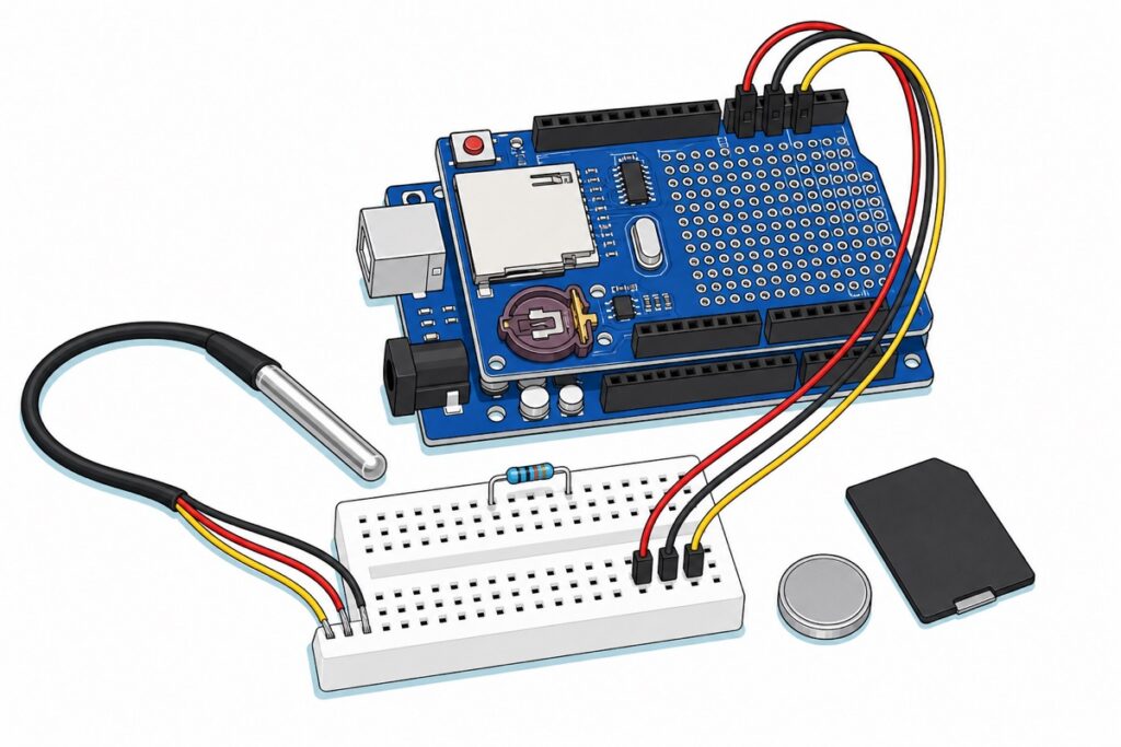
Stack the Data Logging Shield on an Uno, call SD.begin(10) and write comma-separated lines to a file — but those bytes only reach the card when the library’s 512-byte block fills or you call flush(). The shield brings a full-size SD socket and a DS1307 clock to timestamp with. You supply the card and a CR1220 cell.
Low-voltage DC only: USB or the Uno’s barrel jack. Never push or pull the card while the board is powered, and keep the probe’s cut ends dry — only the stainless tube is waterproof.
What is on the Data Logging Shield, and what is not?
The Data Logging Shield arrives fully assembled, so it seats on an Uno straight from the bag. A full-size SD card socket with a spring eject takes the left half of the dark blue board; below it a translucent maroon holder backs up a DS1307 real-time clock. The right-hand third is a prototyping grid, there to solder the wiring into permanently later. Every Uno pin is repeated in the shield’s own female headers, so nothing is buried. The 14-pin chip beside the card socket is a quad buffer doing level shifting: SD cards are strictly 3.3 V parts and an Uno drives 5 V logic, so the shield does the translation a bare card socket would leave to you.
Two things this build needs are not in the bag, and we do not stock either:
- A full-size SD card, not microSD. The shipped Arduino SD library describes itself as accessing “FAT16 and FAT32 files on SD and SDHC cards” (
SdFat.h), and SDHC stops at 32 GB by specification, so a 64 GB exFAT card will not mount. A microSD in a full-size adapter is fine, though the adapter adds a second set of spring contacts — swap adapters before blaming the shield. - A CR1220 coin cell. The holder ships empty, bare blue board showing through its centre. The shield follows the Adafruit reference design and takes the same 12 mm cell. Fully usable without one — the 01/01/2000 section sets out what you lose.
The CS, L1 and L2 holes above the grid, and the two tiny LEDs by the reset button, are unconnected solder pads, not activity indicators. A hands-on walk-through of this exact V1.0 board:
Parts list — the board, the shield, the probe and the wiring that joins them
 Arduino Uno Compatible SMD UNO R3 with Type B Cable - ATMEGA328P with CH340G-Microcontroller Project
 Data Logging Shield Data Logger Module Data Recorder with Built in RTC For Arduino IOT Application
 Temperature Sensor DS18B20 Temperature Measurement Probe WaterProof 18B20
 MB102 Breadboard 170 400 830 Holes Breadboard Donut Board Arduino Prototype Multi Color - MINI BREADBOARD 170 HOLES (WHITE)
 40pcs Dupont Wire 10cm 20cm 30cm for Breadboard DIY Experiment Jumper Wire Breadboard wire - DUPONT WIRE M-M 30CM
 400 pcs 1/4W Resistor Pack Resistor Kit 20 Common Value with 20 each
Parts list
| Item | Price | Qty | |
|---|---|---|---|
 XL830L Digital Multimeter with backlight Portable Multimeter Electronics ProjectMULTIME XL830L Digital Multimeter with backlight Portable Multimeter Electronics ProjectMULTIME | RM25.95 |
Two jobs on this build specifically: confirm on the ohms range which value you actually pulled out of a twenty-value resistor pack, and measure the shield's 5V pad when a card refuses to mount — a sagging USB rail under a hungry card looks exactly like a code fault.
Which Arduino pins does the shield already use?
The Data Logging Shield claims six of the Uno’s pins across two buses: SPI to the card, I2C to the clock. So the probe lands on D2.
| Pin | Claimed by | Free for you? |
|---|---|---|
| D10 | SD chip select (and the ATmega328P’s hardware SS) | No |
| D11, D12, D13 | SPI data and clock to the card | No |
| A4, A5 | I2C to the DS1307 clock | No |
| D0, D1 | Shared with USB serial | Avoid |
| D2–D9, A0–A3 | Nothing | Yes |
On an ATmega328P, D10 is both this shield’s chip select and the hardware SS pin, and the SPI peripheral watches SS — leave it an input, let something pull it low, and the hardware drops into slave mode, so the master stops talking. SD.begin() handles that for you — it calls SPI.begin(), and the AVR core’s SPI.cpp sets pinMode(SS, OUTPUT) there, under the warning “if the SS pin ever becomes a LOW INPUT then SPI automatically switches to Slave, so the data direction of the SS pin MUST be kept as OUTPUT”. Never reclaim D10 afterwards.
Why does the probe need a breadboard and a resistor?
The waterproof DS18B20 ends in three bare tinned flying leads — red for power, black for ground, yellow for data — with no connector on them, while the shield’s only user-accessible interface is female stacking headers. Bare tinned wire will not grip inside a female Dupont shell. A 170-hole mini breadboard settles it: each column of five holes is joined underneath, so the tinned ends and the resistor legs push straight in and male-to-male jumpers carry the nets to the shield. This mini format has no power rails, so 5V and ground live in ordinary columns — and since each column is one net, the three leads need three separate columns: red and black sharing a column is 5V wired straight to ground.
The resistor is not optional, and the reason is the output stage. The DS18B20’s DQ pin is open-drain: it holds a transistor that can pull the line down to ground, and nothing that can drive it up. Released, the line floats at whatever stray charge is nearby. The external resistor to 5V is what supplies the high level, which is why an unresisted probe returns -127.00, the library’s “nothing answered” value, or sits frozen at 85.00, the sensor’s power-on default read before any conversion finished.
The DS18B20 datasheet asks for roughly 5 kΩ, and 4.7 kΩ to 10 kΩ all suit one sensor on this probe’s one-metre lead: the resistor and the bus capacitance form an RC pair, so a bigger resistor makes the line rise more slowly, and only long buses or several sensors run out of margin. Our 400-piece resistor pack prints each value in ink on the bandolier’s paper tape, so there are no colour bands to decode — the 6.8 kΩ strip works well here.
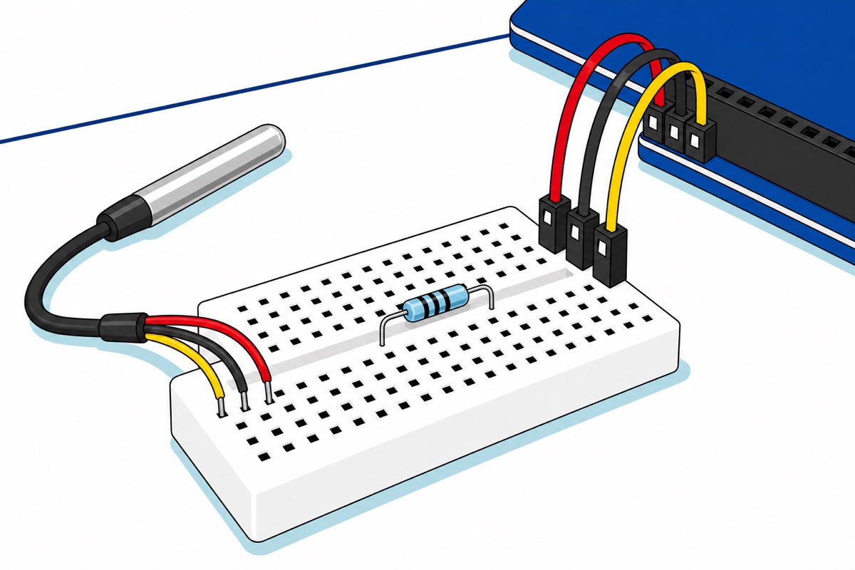
| DS18B20 lead | Goes to | On the shield |
|---|---|---|
| Red (VDD) | 5V | Lower power header |
| Black (GND) | GND | Lower power header |
| Yellow (DQ) | D2 | Upper digital header |
| 4.7 kΩ–10 kΩ resistor | Bridges the red column and the yellow column on the breadboard — that is, DQ up to 5V | |
What sketch writes the readings to the card?
Install SD, RTClib (Adafruit), OneWire and DallasTemperature (Miles Burton) from the Library Manager, and keep the Serial Monitor open at 9600 baud — the sketch halts on any setup failure and prints the reason there. The sketch samples every five seconds, timestamps from the DS1307 and appends one CSV row per reading — the same pattern that logs an HX711 load cell or an MLX90614. Add columns to one file rather than starting new ones — a single wide CSV charts in one go.
// Arduino Uno + Data Logging Shield V1.0 + waterproof DS18B20.
// Writes one CSV row every 5 s to TEMPLOG.CSV on a full-size SD card,
// timestamped by the shield's DS1307 real-time clock.
//
// Shield uses: D10 (SD chip select), D11/D12/D13 (SPI), A4/A5 (I2C for the RTC).
// The sensor therefore lands on D2, with a 4.7k-10k pull-up from D2 up to 5V.
// Low-voltage DC only: USB or the Uno's barrel jack. Never insert or remove
// the card while the board is powered.

#include <SPI.h>
#include <SD.h>
#include <Wire.h>
#include <RTClib.h>
#include <OneWire.h>
#include <DallasTemperature.h>

const uint8_t  SD_CS        = 10;      // this shield's SD chip select
const uint8_t  ONE_WIRE_PIN = 2;       // DS18B20 yellow lead (DQ)
const uint16_t SAMPLE_MS    = 5000;    // one reading every 5 seconds
const uint8_t  FLUSH_EVERY  = 12;      // commit to the card once a minute

RTC_DS1307 rtc;
OneWire oneWire(ONE_WIRE_PIN);
DallasTemperature sensors(&oneWire);

File logFile;
uint8_t  samplesSinceFlush = 0;
uint32_t nextSampleAt = 0;

// Halt loudly instead of logging nonsense.
void stopHere(const __FlashStringHelper *why) {
  Serial.println(why);
  while (1) { }
}

void setup() {
  Serial.begin(9600);

  // D10 is the SD chip select AND the ATmega328P hardware SS pin. SD.begin()
  // calls SPI.begin(), which sets SS to OUTPUT ("the data direction of the SS
  // pin MUST be kept as OUTPUT"), so never reclaim D10 as an input after this
  // point - SPI would drop into slave mode and the card would go silent.
  pinMode(SD_CS, OUTPUT);

  if (!SD.begin(SD_CS)) {
    stopHere(F("No card. Check it is FAT16/FAT32, <=32GB, fully pushed in."));
  }

  Wire.begin();
  if (!rtc.begin()) {
    stopHere(F("No DS1307 on A4/A5. Is the shield seated on all its pins?"));
  }

  // isrunning() reads the DS1307's CH bit. The datasheet says CH comes up SET
  // on first application of power, so with an empty coin-cell holder the
  // oscillator restarts HALTED and the date resets to 01/01/2000 every time.
  if (!rtc.isrunning()) {
    Serial.println(F("RTC was halted - setting it from this sketch."));
    Serial.println(F("Fit a CR1220 if you want the time to survive a power cut."));
    rtc.adjust(DateTime(F(__DATE__), F(__TIME__)));  // compile time, not now
  }

  sensors.begin();
  sensors.setResolution(12);          // 0.0625 C steps, up to 750 ms per reading
  if (sensors.getDeviceCount() == 0) {
    stopHere(F("No DS18B20 answered. Check the pull-up between D2 and 5V."));
  }

  logFile = SD.open("TEMPLOG.CSV", FILE_WRITE);   // 8.3 names only
  if (!logFile) {
    stopHere(F("Could not open TEMPLOG.CSV for writing."));
  }
  if (logFile.size() == 0) {                      // brand new file, add a header
    logFile.println(F("timestamp,celsius"));
    logFile.flush();
  }

  Serial.println(F("Logging to TEMPLOG.CSV"));
}

void loop() {
  if ((int32_t)(millis() - nextSampleAt) < 0) {   // rollover-safe comparison
    return;
  }
  nextSampleAt += SAMPLE_MS;

  sensors.requestTemperatures();                  // blocks ~750 ms at 12 bits
  float celsius = sensors.getTempCByIndex(0);
  if (celsius == DEVICE_DISCONNECTED_C) {         // -127.00: nothing replied
    Serial.println(F("Sensor did not reply - skipping this sample."));
    return;
  }

  DateTime now = rtc.now();
  char stamp[20];
  snprintf(stamp, sizeof(stamp), "%04u-%02u-%02u %02u:%02u:%02u",
           now.year(), now.month(), now.day(),
           now.hour(), now.minute(), now.second());

  logFile.print(stamp);
  logFile.print(',');
  logFile.println(celsius, 2);

  Serial.print(stamp);
  Serial.print(F(","));
  Serial.println(celsius, 2);

  // Those bytes are still in the SD library's 512-byte RAM block. flush()
  // pushes the block and the directory entry onto the card; doing it every
  // sample costs time and flash wear, so we do it once a minute instead.
  if (++samplesSinceFlush >= FLUSH_EVERY) {
    logFile.flush();
    samplesSinceFlush = 0;
  }
}
Three details. TEMPLOG.CSV is an 8.3 name — up to eight characters, a dot, up to three more — because that is all this library speaks, and a longer one silently fails to open. setResolution(12) buys 0.0625 °C steps at the cost of a conversion of up to 750 ms that requestTemperatures() waits for, so the loop stalls for most of a second per sample. And the timing test is (int32_t)(millis() - nextSampleAt) < 0 rather than millis() < nextSampleAt, so it survives millis() wrapping at 49.7 days — the horizon a logger is built to cross.
Why is my CSV empty after a power cut?
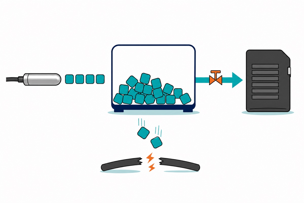
Because writing to a file and writing to the card are different events. The SD library keeps one 512-byte block in RAM — SdFat.h declares static cache_t cacheBuffer_ under the comment “512 byte cache for device blocks” — and your println() lands there. The card is touched only when that block fills, on flush(), or on close(). Pull the plug in between and those rows never existed as far as the card is concerned.
The second half is why the file reads as empty rather than merely short. flush() calls SdFile::sync(), which writes the cached block and copies the file’s current size back into its directory entry. Until that happens the directory still records the old size, so bytes that physically reached the card sit beyond what the file claims to contain.
Flushing after every sample is the opposite mistake. Each flush is two writes — the data block and the directory entry — plus the stall while the card acknowledges them, and flash cells have a finite number of erase cycles for the controller to spread around. Pick a cadence: this sketch flushes every twelfth sample, once a minute at five-second spacing, so a power cut costs at most a minute of readings and a day’s run costs 1,440 flushes instead of 17,280.
Unplug the USB lead before taking the card out — pulling a card live is the classic route to a corrupt file system. TEMPLOG.CSV is plain text, so any spreadsheet charts it, and FILE_WRITE appends: the next power-up continues the same file instead of overwriting it.
Why is every row stamped 01/01/2000?
The DS1307 does not merely come up with the wrong time — it comes up stopped. Its datasheet states that on first application of power the registers reset to 01/01/00 and the CH bit in the seconds register is set to 1 — and CH set means the oscillator is halted. A backup cell is what stops “first application of power” recurring at every switch-on, so an empty holder restarts the clock halted every time and every row carries the same frozen date. The datasheet also says VBAT must be grounded where no backup supply is used, and an empty holder leaves that pin floating instead — one more reason to fit the cell.
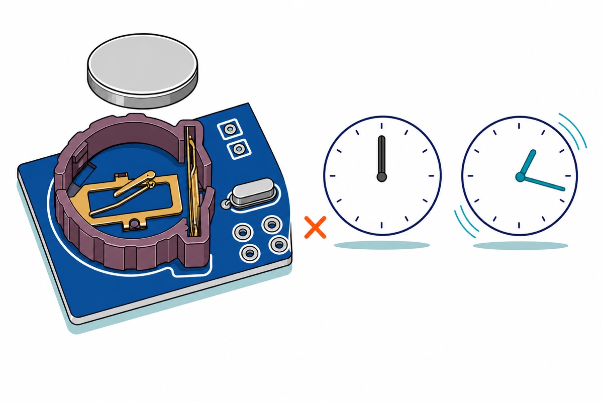
The sketch surfaces this. rtc.isrunning() reads exactly that CH bit, and on a halted clock the sketch starts it and sets it from __DATE__ and __TIME__ — macros holding the moment the sketch was compiled. Without a cell that is the honest ceiling: intervals stay perfect, absolute dates reset to compile time at each power-up. Fitting a cell later is the trap — the clock is running by then, so that block never fires again and every row carries a stale compile time. Fit it before the first upload, or move rtc.adjust() above the isrunning() test for one upload.
Fit a CR1220 and the clock runs through power cuts. It still drifts, because the DS1307 counts a plain 32.768 kHz crystal with no temperature compensation and a crystal’s frequency moves with temperature — a logger in a hot roof space wanders faster than one on a desk. If timestamps must still be right in six months, the DS3231 in our digital clock guide puts crystal and thermometer inside the chip.
Common mistakes we see
A microSD card that will not fit. The socket is full-size SD with a spring eject, not microSD. A plain full-size adapter solves it — format the card FAT32 and keep it to 32 GB or under.
A file that exists but is empty, or stops mid-line. An unflushed buffer, not a fault: the power went while a block was still in RAM. Flush more often, or give the logger a deliberate stop — a button or a Serial command that calls close() — and cut the power only after that. Unplugging the sensor will not save it: that only stops new rows, and the ones already buffered are still in RAM. Until you add that stop, the flush cadence you choose is your loss window.
Every row dated 01/01/2000. The holder is empty and the DS1307 restarts halted. Fit a CR1220, or log elapsed milliseconds in a second column and accept a resetting time base.
-127.00, or a frozen 85.00. Both point at the 1-Wire line, not the sensor. Check the resistor really bridges the yellow column to the red one.
FAQ
Does the Arduino Data Logging Shield take a microSD card?
No — it is full-size SD with a spring eject. A microSD in an adapter works fine. Format FAT32 and stay at 32 GB or under: the Arduino SD library reads FAT16 and FAT32 on SD and SDHC cards only.
Why is my Arduino SD card file empty when Serial showed the readings?
The library buffers one 512-byte block in RAM and commits it only when it fills, on flush(), or on close(). Serial output skips that buffer, so it looks perfect while the card has nothing.
Does the Arduino data logging shield need a CR1220 battery?
Not to log. Without a CR1220 the DS1307 restarts halted at 01/01/2000 on every power-up, so the sketch must set the time each boot. Readings and intervals are unaffected.
Why does my DS18B20 read -127 on the Arduino data logging shield?
Its DQ pin is open-drain — it can pull the line low but cannot drive it high — so it needs a 4.7 kΩ to 10 kΩ resistor from the yellow lead up to 5V. Without one the line floats and the library reports -127.00, “no device replied”.
Last updated August 2026. Stuck? Chat with us on WhatsApp.
