

Tutorials
How to Solder Enamelled Wire, Ribbon Cable and Stranded Wire (and What a Pencil Iron Can’t Solder)
Oct
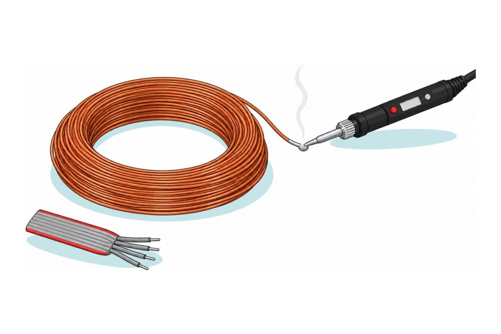
When solder refuses to stick to a wire even though your iron works fine on everything else, the wire itself is the problem. Enamelled (magnet) wire carries a clear insulating coat that must be scraped or burned off first; PVC ribbon cable melts if you hold the iron on too long, so the key is a short touch; stranded wire gets a thin tin at the tip only. Aluminium, stainless steel and steel plate are simply beyond a 60–80 W pencil iron.
Test first: try soldering a component leg or a clean PCB pad with the same iron. If the solder balls up and won’t flow there too, the problem is your iron, tip or flux, and the answer is in our guide to choosing a soldering iron and flux. If solder flows smoothly there but not on your wire, the wire material is the culprit, and this page is for you. For standard through-hole joints, see how to solder header pins.
Why won’t solder stick to enamelled wire when it looks like bare copper?
Enamelled wire (also called magnet wire, or kawat email in Indonesia) is solid copper wire coated with a polymer film thinner than a human hair. That film is clear or amber-tinted, so what you see is the copper colour underneath. It’s the wire in coils you wind yourself, relays, small transformers and small DC motors. To check, set your multimeter to the ohms range and touch both probes to the unscraped surface of the wire, a few centimetres apart: bare copper reads close to 0 Ω, while enamelled wire usually reads “OL” because the probes are only touching the coating.
Solder only bonds with bare metal: molten tin forms an alloy with the surface it touches. Enamel coating is plastic, so there’s nothing to react with, and surface tension pulls the solder into a ball that “slides” off the wire. Flux alone won’t help: rosin strips metal oxides, not plastic film. The coating has to come off first, either with a blade or with heat.
Kit for all three techniques: enamelled wire, ribbon cable and stranded wire
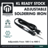 80W Electronics Soldering Iron with LCD Display Ajustable Temperature Microconstroller Electronic Project
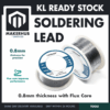 50g Soldering Wire Lead with Flux Core 1mm Diameter
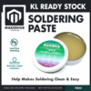 20g Soldering Paste Rosin Flux Lead-Free Blending Easy Solder
 KF301 Terminal Block PCB Connector PCB Terminal Block 2P 3P 4P - KF-301 TERMINAL BLOCK (2P)
 Deli Cutter Black Knife DIY Cutter Tool Black Precision Cutting Alloy Steel
The wire itself isn’t on the list because it’s already in your project. The two KF301 screw terminals are practice targets for stranded wire, and the craft cutter is your tool for scraping off enamel.
Parts list
 Soldering Iron Stand Metal Spring Holder Support Station Base Heat Resistant Workshop Electronics DIY Tool
 Soldering Iron Tip Cleaner with Container Steel Ball Tip Cleaning
 Needle Nose Plier Professional Multi-purpose Precision Electronics Tool
 Sodering Clip Stand with Magnifying Glass Soldering Holder Electronics Project Assistance Holder
Bench comforts: the stand and brass wire ball keep your iron tip in good shape, needle-nose pliers hold fine wire while soaking up heat before it reaches the insulation, and the magnifier clip holds your work while both hands are busy with iron and solder.
How do you remove the coating from enamelled wire: scrape it or burn it?
The chemistry of the enamel decides how you remove it. Polyurethane coatings, common on fine wire, are designed to be soldered straight through: at high temperature the urethane bonds break down and the coating bubbles out into the molten solder. Polyimide and amide-imide coatings, common on motors, are designed not to break down at iron temperatures.
| Method | What physically happens | For coating type | Iron temperature |
|---|---|---|---|
| Scrape with a craft cutter | The blade mechanically scrapes off the polymer film | All types — the safe route when unsure, except for very fine wire | Normal, 300–350 °C, for tinning afterwards |
| Burn off in a solder bead | The coating breaks down and bubbles out, and the solder wets the copper directly | Polyurethane (solderable type) | ~390 °C for wire 0.5 mm and finer, ~430 °C for thicker wire |
| Rosin flux paste | Cleans oxide off copper that’s already exposed — does not remove the coating | A helper for both methods above | — |
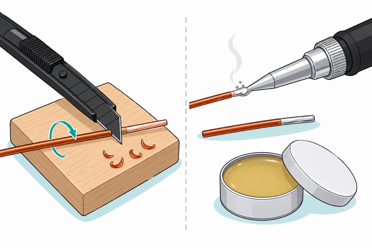
Scraping. Lay the end of the wire on a wooden block. Stand the blade of the craft cutter upright at 90° to the wire and draw it away from your fingers — scraping, not cutting. Rotate the wire a quarter turn with each stroke until you have 3–5 mm of bright salmon-pink copper all the way round. Press lightly: a nick in fine wire becomes a break point when it’s bent later. Straight away, dab on a little flux paste and tin that section at 300–350 °C; any dull patch that refuses to turn silver is leftover coating, so scrape there again. Wire finer than about 0.1 mm, like you’d find in a relay coil, snaps easily when scraped; wire that fine is usually polyurethane-coated, so try the burn-off method below first.
Burning off in a solder bead. The usual 300–350 °C isn’t enough to break down a polyurethane coating. Wire maker MWS lists the solder temperature of its nylon-overcoated polyurethane enamel (thermal class 180) as around 390 °C for 24 AWG (0.5 mm) and finer, and 430 °C for thicker wire; the standard IEC 60317-20 solderability test for regular polyurethane (class 155) is run in a 390 °C solder bath. That’s why the dial on an adjustable 180–480 °C iron matters: turn it up to around 400 °C for this job (430 °C for wire thicker than 0.5 mm), then turn it back down afterwards, because the tip oxidises faster at high temperature. Melt a fresh bead of flux-core solder wire on the tip, dip 3–5 mm of the wire end into it and hold for 2–3 seconds. Small bubbles mean the coating is breaking down. Draw the wire slowly out through the bead. Melt a new bead for each end, because the rosin in the old one has burned off. Fumes from burning enamel are harsher than rosin smoke, so open a window or run a fan.
This recording of the dipping process is worth watching before you try it yourself:
If the coating only blackens without bubbling at 400–430 °C, it’s a high-temperature enamel. Stop and scrape instead; cranking the dial to 480 °C only burns your tip.
How do you know the coating is fully gone? First, look: the tinned section should be shiny silver all the way round, with no amber or black streaks. Second, measure. Copper wire of 0.2 mm has a resistance of about 0.55 Ω per metre (copper’s resistivity divided by the wire’s cross-sectional area), so a 10-metre coil should read around 5.5 Ω across its two ends on a multimeter. The number depends on the length and thickness of the wire (a fine relay coil can read hundreds of ohms), so what matters is that you get a number at all. A reading of “OL” means an open circuit: usually coating is still left on one of the ends, or the wire is broken, either inside the coil or at a nick from scraping.
How do you solder ribbon cable or flexible cable without melting the insulation?
Standard ribbon cable (type UL2651) uses PVC insulation rated for 105 °C, while leaded solder only becomes fully liquid at around 190 °C. There’s no iron temperature that melts solder without also softening PVC. On top of that, the copper conductors conduct heat roughly two thousand times better than PVC. Those fine strands carry the tip’s heat straight under the insulation, and the PVC shrinks back or melts. The only thing you control is how long the heat flows.
That’s why a cooler iron doesn’t help. The rate at which heat flows into a joint is proportional to the temperature difference. At 280 °C, the tip is only about 95 °C above the solder’s melting point; at 350 °C the gap is about 165 °C. Just before the solder melts, heat flows in nearly twice as fast with the hotter iron. The joint needs roughly the same amount of heat to melt regardless of iron temperature; what changes is the time. Starting from room temperature, a 350 °C iron brings the joint to melting temperature in about two-thirds of the time a 280 °C iron takes, and less time means less heat has a chance to spread along the strands and under the insulation.
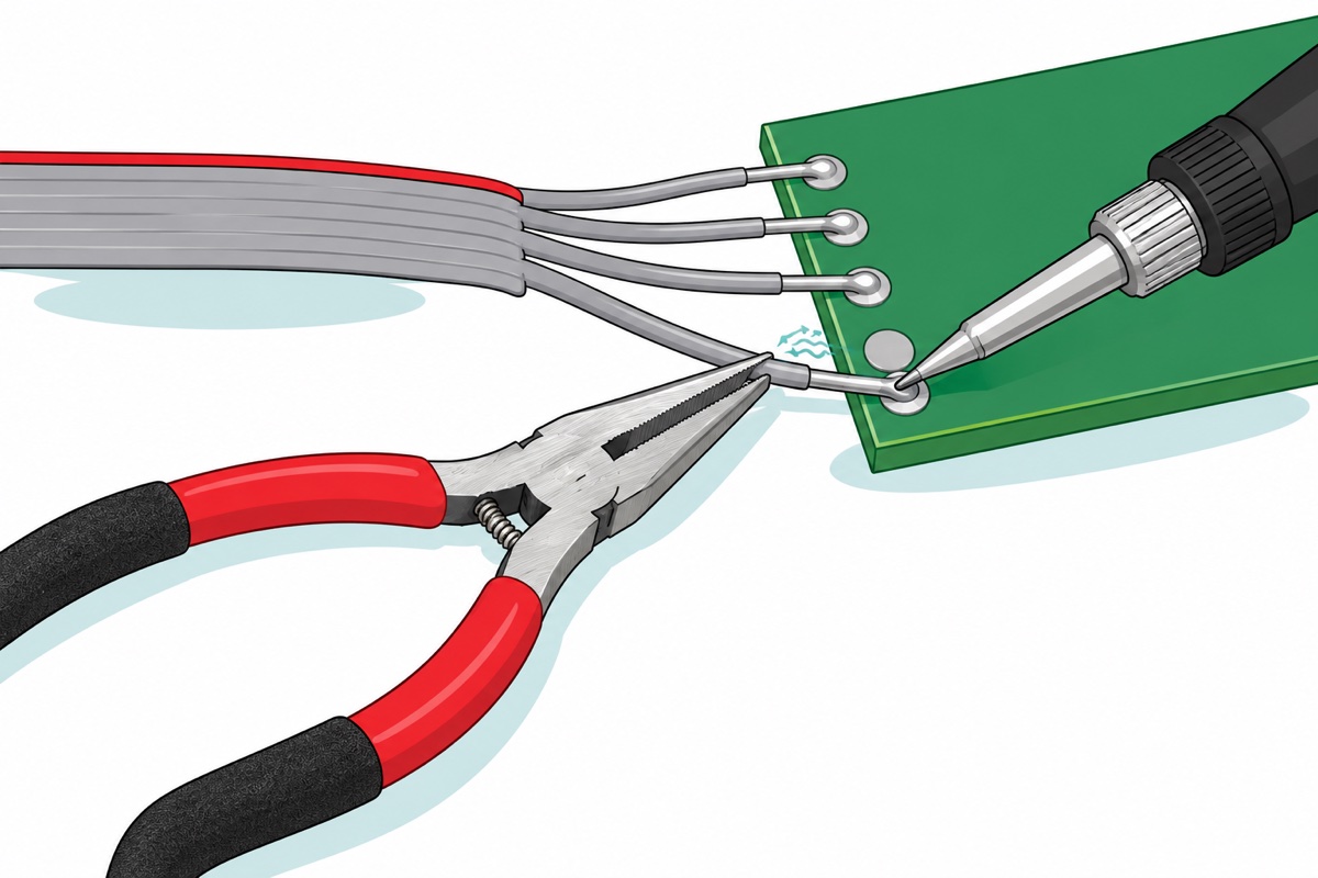
The trick is to break the joint into short touches:
- Split the ribbon along the grooves between conductors with a craft cutter, 10–15 mm back, so each wire is free.
- Lightly score the insulation all the way round, strip 2–3 mm, and twist the fine strands together. If any strands break, cut off the end and start again.
- Set the iron to 330–350 °C. Tin the wire end and the pad separately, each with a touch of under one second and a dab of flux paste. Ribbon conductors are usually tinned copper, so solder takes to them straight away.
- Lay the tinned wire on the tinned pad and touch for 1–2 seconds. The two layers of tin flow together without any new solder.
If the stripped section is short, clamp the wire with needle-nose pliers between the joint and the insulation. The steel jaws are far bigger than the fine strands, so they soak up heat before it can creep into the PVC. Cover the joint with heat-shrink (see our insulation tape vs heat-shrink guide). Then tie or glue the cable to the board so flexing doesn’t land on the joint: solder that wicks up makes the end of the strands stiff, and strands snap at that stiff-to-flexible boundary (the stranded wire section below explains why).
If your “flexible cable” is very soft and rubbery, it’s most likely silicone-insulated, which handles around 200 °C and is much easier to solder.
If your “flexible cable” is instead a thin amber or white film strip with printed copper traces, like the ones that connect LCD screens, that’s an FFC or FPC cable. It’s designed to push into a ZIF connector, not to be soldered with a pencil iron: the trace pitch is often 0.5–1.0 mm, about as wide as the iron’s conical tip itself, so solder easily bridges two neighbouring traces.
How do you tin stranded wire for a screw terminal without stray strands?
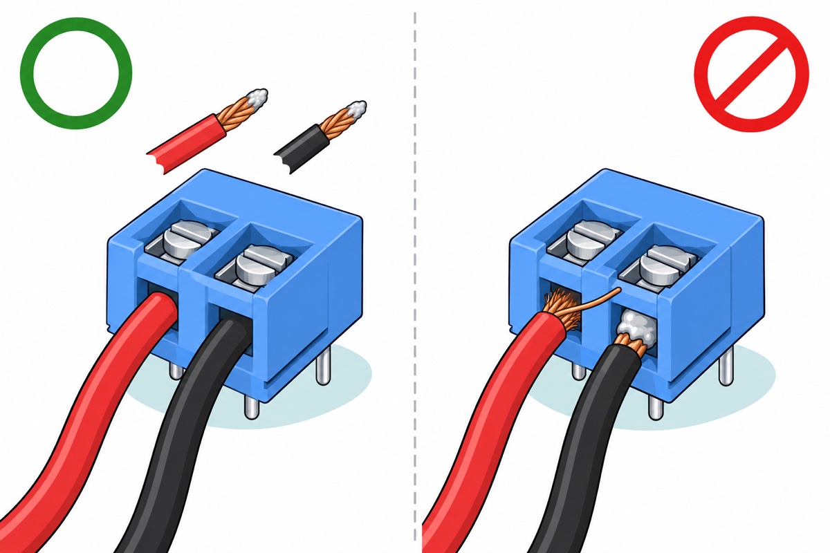
On a KF301 screw terminal with roughly 5 mm pitch, a single stray copper strand is enough to touch the neighbouring cage and cause a short circuit.
- Strip the insulation to the depth of the terminal cage (measure by holding the wire alongside it) so no copper is exposed outside.
- Twist the strands tightly in one direction.
- Add a dab of flux, then give it a quick touch with a tip carrying a little solder, at the very end only. A proper tin still shows the shape of the strands, not a smooth rod.
- Insert until the insulation meets the face of the terminal, tighten, and tug the wire to test it.
Two reasons to keep it thin. First, solder that wicks under the insulation turns that section into a stiff rod; every bend concentrates at the stiff-to-flexible boundary, and the strands snap there, hidden inside the insulation. Second, creep: metals start to flow slowly under constant pressure once their temperature exceeds about 35% of their melting point in kelvin. Leaded solder melts at 183 °C, which is 456 K; room temperature at 298 K is already 65% of that. Copper, which melts at 1,358 K, sits at just 22%. So under screw pressure the solder slowly flows out and the grip loosens, while copper does not.
That’s why industry doesn’t tin wire for screw terminals; it uses crimped ferrules instead. For low-voltage signal wires, a thin tin is acceptable if you re-tighten after a few days. Wires carrying motor or power supply current are left twisted and untinned, because a loosening grip raises contact resistance, and at high current even that small resistance turns into heat (power = current² × resistance). For these wires, follow steps 1, 2 and 4 only, and check there are no stray strands before tightening the screw. Never tin wires going into a 240 V mains plug or socket: a loosening connection runs hot, and that heat can start a fire. Every technique on this page is for low-voltage DC circuits.
What will a 60–80 W pencil iron never solder, no matter how long you try?
Aluminium, stainless steel and steel plate fail for two separate reasons. The first is chemistry, as covered in our guide to choosing a soldering iron and flux: aluminium regrows its oxide skin within seconds and needs a dedicated aluminium flux. Stainless steel behaves the same way: the chromium oxide layer that makes it stainless is exactly what repels solder. Rosin can’t strip either of them. Plain steel is no better — its rust needs acid flux, and acid flux residue keeps eating away at copper, so it has no place near electronics.
The second reason is heat, and on sheet or plate metal it still stops you even when the chemistry is right. Solder only wets a surface whose own temperature is above the solder’s melting point. Take a 10 × 10 cm steel plate, 2 mm thick: its mass is about 157 g (20 cm³ × 7.85 g/cm³). Raising the whole thing from 30 °C to 230 °C takes about 15,000 joules (157 g × 0.49 J/g·°C × 200 °C) — more than three minutes at a full 80 W, even if no heat were lost at all. But a hot plate loses heat to the air through both faces, about 50 W at around 200 °C. And a fine conical tip only delivers part of the iron’s 80 W, because all the heat has to pass through a contact point the size of a pencil tip. The plate levels off below solder temperature and never gets there. Heating just one spot doesn’t help either: the steel keeps conducting heat away from the spot under the tip into the rest of the plate for as long as the plate is cold.
| Material | Chemistry problem (rosin flux) | Heat problem (pencil iron) | What actually works |
|---|---|---|---|
| Enamelled wire | Plastic coating, not oxide | None — fine wire heats up quickly | Scrape, or burn off in a solder bead if polyurethane |
| PVC ribbon cable | None — tinned conductors | Insulation melts with a long touch | Tin separately, 1–2 second touch |
| Stranded wire | None | None | Twist; thin tin at the tip for signal wires only |
| Aluminium | Oxide regrows, rosin can’t cope | Conducts heat away quickly | Screws, clips or crimp lugs |
| Stainless steel | Chromium oxide, rosin can’t cope | Large sheets soak up heat | Screws or rivets |
| Plain iron or steel plate | Rust needs acid flux that corrodes electronics | Thermal mass exceeds an 80 W iron | Bolts or rivets; joining heavy metal is a job for welding or brazing (flame or arc, not an iron) |
If what you really want is to connect a wire to a metal plate or chassis, crimp a ring terminal onto the end of the wire and bolt it to the plate, with a star washer underneath that bites through paint and rust so the electrical contact stays solid.
Common mistakes when soldering difficult materials
Slathering flux on enamelled wire and waiting for it to take. Rosin doesn’t dissolve plastic; remove the coating first.
Scraping hard on fine wire. A tiny nick becomes a break point later; press lightly and rotate the wire.
Turning the iron down for ribbon cable so it “won’t melt”. A cooler iron takes longer, and that time is what melts the insulation.
Tinning stranded wire so heavily it turns into a rod. Tight on day one, loose once the solder creeps under the screw.
Holding the iron on a steel plate for minutes while adding more solder. The solder melts at the tip but the plate never reaches temperature, so the blob just sits on the surface without bonding. It looks stuck, but pops off with a light push.
FAQ
Why won’t solder stick to the fine copper wire from a coil or motor?
That wire is enamelled wire, coated with a clear plastic film that solder can’t wet. Scrape the coating off, or dip the end into a solder bead at around 400 °C if the coating is polyurethane.
What iron temperature burns off enamelled wire coating?
Around 390 °C for polyurethane wire 0.5 mm and finer, and 430 °C for thicker wire, held for 2–3 seconds in a fresh bead. A coating that only blackens needs to be scraped.
Can you solder a steel plate with an ordinary soldering iron?
Not with a 60–80 W pencil iron: it needs acid flux that corrodes electronics, and the plate sheds heat faster than the iron can supply it. Use bolts or rivets.
Should you tin stranded wire before putting it in a screw terminal?
For low-voltage signal wires, tin thinly at the tip and re-tighten after a few days. High-current wires are left untinned. Never tin wires for a 240 V plug or socket.
Why does ribbon cable melt when I solder it?
Its PVC insulation is rated for only 105 °C and the copper carries heat straight under it. Tin the wire and pad separately so the final joint is just a 1–2 second touch at 330–350 °C.
Last updated October 2026. Stuck? Chat with us on WhatsApp.
