

Tutorials
Build an ESP32 Air Quality Monitor for the Haze Season (PM2.5 + CO2)
Jun
To build your own air quality monitor with an ESP32, wire the GP2Y1010AU0F optical dust sensor to an ADC1 pin for PM2.5 trends and the SCD30 CO2 sensor to the I2C bus, then display both readings on a 0.96-inch OLED. One sketch handles everything — the full code is below. This build shows the air trend inside your home; it is not a substitute for official air quality index readings.
Why does this project use two sensors?
The GP2Y1010AU0F dust sensor and the SCD30 CO2 sensor answer two different questions. During jerebu (the seasonal haze), the question is “how much fine particulate is getting into my house” — that is the dust sensor’s job, detecting infrared light reflecting off particles in the air. A closed, air-conditioned room raises a different question: “is there enough fresh air in here” — and CO2 is the most reliable indicator of ventilation.
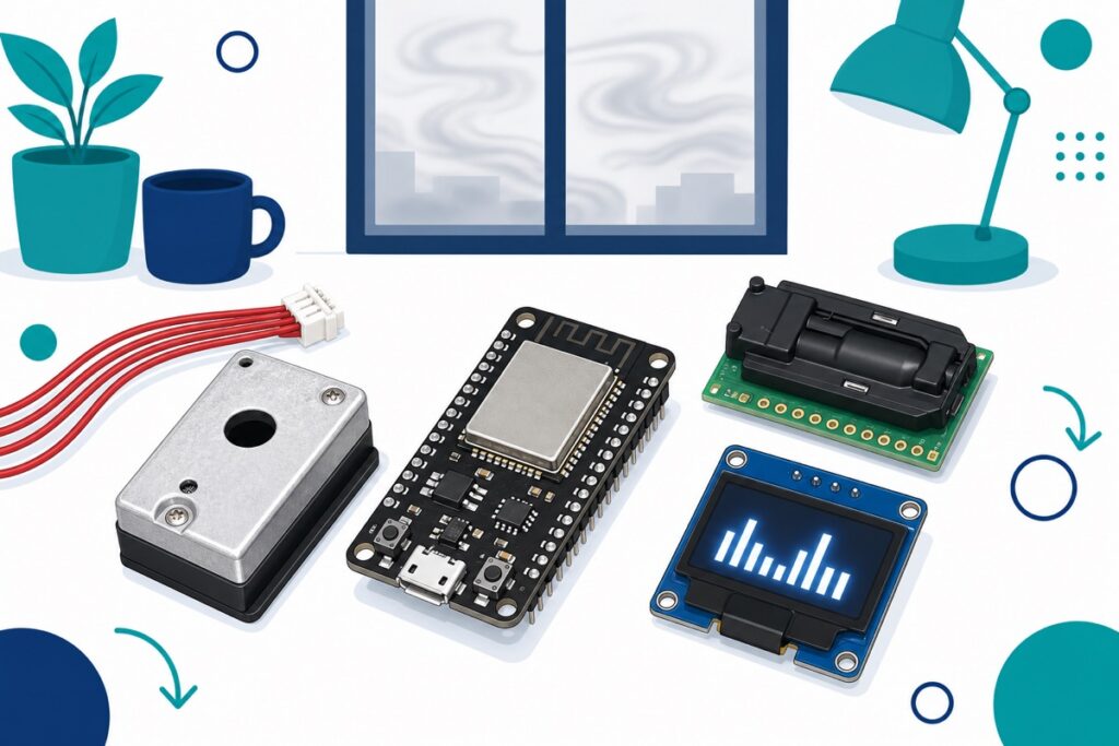
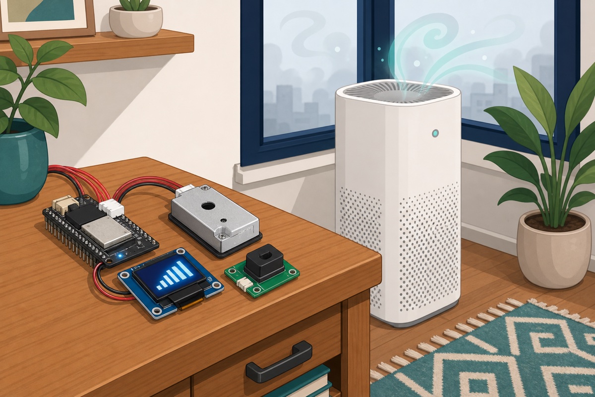
Get to know each component by sight. The dust sensor comes in an aluminium casing with a round hole in the middle and a red 6-wire cable ending in a white JST plug. The SCD30 is a green breakout PCB with a black sensor block — its castellated pads ship without headers fitted, so you solder them on yourself. See our guide on how to solder header pins if this is your first time. The brain is the NodeMCU-32S (micro-USB, CP2102 USB chip), and the display is a 0.96-inch OLED with white pixels on a blue PCB.
Parts list
 NodeMCU ESP32 Wi-Fi + Bluetooth Development Board CH340/CP2012 - For IOT Project - ESP-32(CP2102)
 PM2.5 Air Quality Sensor Module Digital Dust Detector DC01
 SCD30 High Precision NDIR CO2 Carbon Dioxide Temperature Humidity Sensor Module I2C Interface Arduino Compatible
 0.96‘ OLED Display Module Blue White Screen I2C IIC Serial 128X64 LCD Display Board - 0.96' OLED WHITE
One important note: this dust sensor must be paired with a 150Ω resistor and a 220µF electrolytic capacitor — those values are set by the Sharp datasheet itself, not a preference. Both are ordinary workshop parts most makers already keep on hand, which is why they are not in the list above. If you want basics like these always in stock, our component starter kit is an easy way to start.
Can this device give an API reading like the official reports?
API (Indeks Pencemar Udara, Malaysia’s official Air Pollutant Index) is calculated by the Department of Environment from calibrated reference monitoring stations. It is not a raw PM2.5 reading — each major pollutant (PM2.5, PM10, ozone, SO2, NO2 and CO among them) gets its own sub-index, and the highest sub-index becomes the API figure. The PM2.5 sub-index is calculated over a 24-hour average, not the reading at that moment.
Optical infrared sensors like the GP2Y1010AU0F give you a relative trend, not a calibrated measurement. Their readings are inflated by humidity — and Malaysia is humid — so never quote the number as “my home’s API”.
So what is it good for? Plenty, actually. You can watch your room’s air deteriorate when a neighbour burns rubbish, confirm whether closing the windows and running an air purifier actually helps, follow the trend across the day, or collect real data for a school science project. The SCD30 is a different story altogether: it is a ventilation indicator — is this room stuffy or not — a separate question from the haze outside. Don’t mix the two up.
How do I wire all the sensors?
The ESP32 has two banks of ADC pins, and pin choice really matters here. The ADC2 pins are shared with the WiFi radio — while WiFi is active, ADC2 readings are blocked. This project is an obvious candidate for WiFi later, so the dust sensor’s analog output must go to an ADC1 pin (GPIO32 to GPIO39) — we use GPIO34.
One more thing: the Sharp datasheet shows the sensor output can reach 3.4V and above in heavy dust, past the ESP32’s 3.3V input limit. The fix is a simple voltage divider — 10kΩ in series, 20kΩ to GND — so the ADC only ever sees two thirds of the real voltage (about 2.3V maximum, comfortably within the ADC range).
| Component | Pin / wire | Connect to |
|---|---|---|
| Dust sensor (6 wires, in JST order) | Wire 1 (V-LED) | 150Ω resistor → VIN (5V). 220µF capacitor from wire 1 to GND, negative leg at GND |
| Wire 2 (LED-GND) | GND | |
| Wire 3 (LED) | GPIO25 | |
| Wire 4 (S-GND) | GND | |
| Wire 5 (Vo) | 10kΩ → GPIO34, then 20kΩ from GPIO34 to GND | |
| Wire 6 (Vcc) | VIN (5V) | |
| SCD30 | VDD | 3V3 |
| GND | GND | |
| TX/SCL | GPIO22 | |
| RX/SDA | GPIO21 | |
| OLED 0.96″ | GND | GND |
| VCC | 3V3 | |
| SCL | GPIO22 | |
| SDA | GPIO21 |
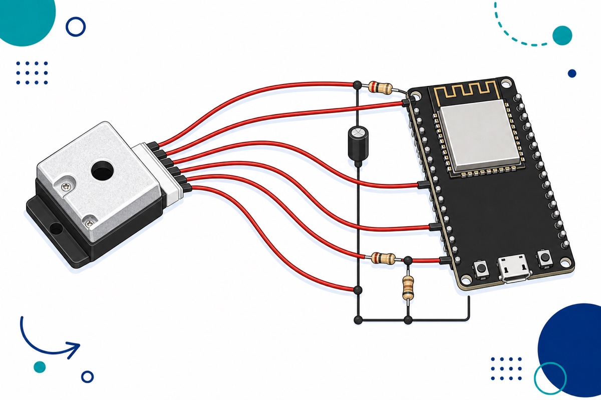
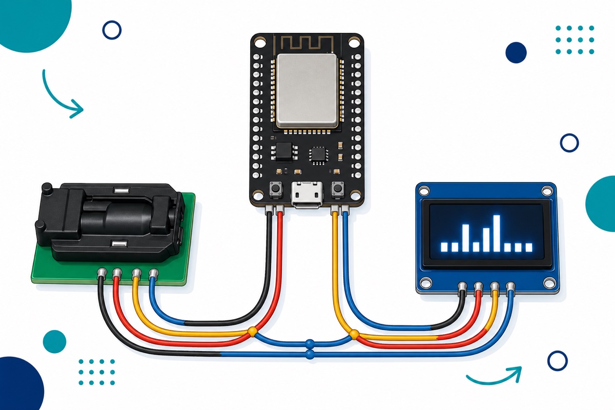
Note that our OLED’s header is printed GND, VCC, SCL, SDA — an unusual order. Accidentally swapping VCC and GND can destroy the module on the spot, so double-check before you apply power.
The SCD30 and the OLED sit on the same I2C bus (SDA=GPIO21, SCL=GPIO22 — the ESP32’s default I2C pins) at different addresses: 0x61 for the SCD30 and 0x3C for the OLED, so there is no conflict. Leave the SEL pad on the SCD30 unconnected — that is what selects I2C mode. A technical note: the SCD30 uses I2C clock stretching (30ms on every read, up to 150ms once a day) — the ESP32’s default 100kHz is the SCD30’s maximum and usually runs fine; if reads fail often, Sensirion recommends 50kHz or lower (add Wire.setClock(50000); after Wire.begin()).
What code reads PM2.5 and CO2 at the same time?
This sketch needs three libraries from the Arduino Library Manager: Adafruit SCD30 (accept the Adafruit BusIO and Adafruit Unified Sensor dependencies when prompted), Adafruit GFX Library and Adafruit SSD1306. The basic pattern is the same as our DHT11 + OLED temperature monitor.
The most critical part is the infrared LED pulse. The Sharp datasheet specifies a 10ms cycle with a 0.32ms pulse width, and the sample is taken 0.28ms after the LED turns on. Getting this timing wrong is the number one cause of nonsense readings.
// Air quality monitor: dust (GP2Y1010AU0F) + CO2 (SCD30) + OLED
// Board: ESP32 Dev Module / NodeMCU-32S
#include <Wire.h>
#include <Adafruit_SCD30.h>
#include <Adafruit_GFX.h>
#include <Adafruit_SSD1306.h>

const int PIN_LED_IR = 25;        // dust sensor wire 3 (IR LED control, active LOW)
const int PIN_VO     = 34;        // wire 5 -> voltage divider -> GPIO34 (ADC1)
const float FAKTOR_DIVIDER = 1.5; // 10k/20k divider: real voltage = reading x 1.5

Adafruit_SCD30 scd30;
Adafruit_SSD1306 oled(128, 64, &Wire, -1);

float voltanBaseline = 3.3;       // tracked automatically: lowest voltage = cleanest air
float co2 = 0, suhu = 0, lembap = 0;

// One pulse per the Sharp datasheet: LED ON -> 0.28ms -> sample -> LED OFF -> pad out to 10ms
float bacaVoltanDebu() {
  digitalWrite(PIN_LED_IR, LOW);              // LOW = IR LED on
  delayMicroseconds(280);                     // wait 0.28ms before sampling
  uint32_t mv = analogReadMilliVolts(PIN_VO); // ADC reading in millivolts (calibrated)
  digitalWrite(PIN_LED_IR, HIGH);             // LED off (pulse width ~0.32ms)
  delayMicroseconds(9620);                    // complete the ~10ms cycle
  return (mv * FAKTOR_DIVIDER) / 1000.0;      // real voltage at the Vo pin
}

float purataVoltanDebu() {
  float jumlah = 0;
  for (int i = 0; i < 30; i++) jumlah += bacaVoltanDebu(); // average of 30 pulses
  return jumlah / 30.0;
}

void setup() {
  Serial.begin(115200);
  pinMode(PIN_LED_IR, OUTPUT);
  digitalWrite(PIN_LED_IR, HIGH);   // make sure the IR LED starts off
  Wire.begin(21, 22);               // SDA=21, SCL=22 (ESP32 defaults)

  if (!oled.begin(SSD1306_SWITCHCAPVCC, 0x3C)) { // OLED I2C address
    Serial.println("OLED tak dijumpai - semak wiring");
    while (true) delay(10);
  }
  if (!scd30.begin()) {             // SCD30 I2C address is 0x61
    Serial.println("SCD30 tak dijumpai - semak solder dan wiring");
    while (true) delay(10);
  }

  oled.clearDisplay();
  oled.setTextSize(1);
  oled.setTextColor(SSD1306_WHITE);
  oled.setCursor(0, 0);
  oled.println("Sensor memanas...");
  oled.display();
  delay(2000);
}

void loop() {
  float voltanDebu = purataVoltanDebu();

  // Clean-air baseline: the lowest voltage ever seen
  if (voltanDebu < voltanBaseline) voltanBaseline = voltanDebu;

  // Dust estimate: typical sensitivity 0.5V per 0.1mg/m3 (Sharp datasheet)
  float debu = (voltanDebu - voltanBaseline) / 0.005; // ug/m3 - trend ESTIMATE only
  if (debu < 0) debu = 0;

  if (scd30.dataReady() && scd30.read()) {
    co2    = scd30.CO2;
    suhu   = scd30.temperature;
    lembap = scd30.relative_humidity;
  }

  oled.clearDisplay();
  oled.setCursor(0, 0);
  oled.print("Debu: "); oled.print(debu, 0);   oled.println(" ug/m3");
  oled.print("CO2 : "); oled.print(co2, 0);    oled.println(" ppm");
  oled.print("Suhu: "); oled.print(suhu, 1);   oled.println(" C");
  oled.print("RH  : "); oled.print(lembap, 0); oled.println(" %");
  oled.display();

  Serial.printf("V=%.2fV debu=%.0fug/m3 CO2=%.0fppm\n", voltanDebu, debu, co2);
  delay(2000);
}
How do I make sense of the readings and calibrate them?
The GP2Y1010AU0F outputs a typical 0.9V even in clean air (anywhere from 0 to 1.5V depending on the unit), then rises roughly 0.5V for every 0.1mg/m³ of dust. That is why the clean-air baseline matters so much: power the device up in your cleanest room first so the sketch can record the minimum voltage as its zero point. Without a baseline, your µg/m³ figure is hanging in mid-air.
Read the trend, not the digits. If the display doubles after you open a window during the haze, that is a real signal; whether the value is exactly 80 or 95 µg/m³ is not a question this class of sensor can answer. High humidity also pushes readings up, so don’t panic over a spike in the damp early morning.
For the SCD30, the Sensirion datasheet states an accuracy of ±(30ppm + 3% of reading) across the 400 to 10,000ppm range — plenty for ventilation decisions. The automatic self-calibration (ASC) feature comes with conditions: the sensor needs continuous power for at least 7 days and a breath of fresh air (~400ppm) for at least 1 hour every day. If your unit sits 24 hours in a sealed room, ASC has no reference — open a window briefly each day, or leave ASC switched off (the sensor’s default).
What common mistakes do we keep seeing?
The same patterns repeat with the GP2Y1010AU0F and SCD30, so run through this list before you suspect a faulty sensor.
Skipping the resistor and capacitor. Without that 150Ω/220µF network, the IR LED pulse is unstable and the readings turn completely random. These are not “upgrade” parts — they are part of the sensor’s circuit.
Dust output on an ADC2 pin. Everything looks fine during testing, then the readings die the moment WiFi comes on. Move it to GPIO32 through 39 and the problem disappears.
VCC/GND reversed on the OLED. The GND, VCC, SCL, SDA order genuinely confuses anyone used to VCC-first modules — and this mistake can kill the module instantly.
SCD30 not detected at 0x61. Almost always a cold solder joint on the castellated pads. Reflow every connection and try again.
Powering the dust sensor from 3.3V. It is a 5V sensor — feed it from the VIN pin when running on USB power, and only then does the output voltage mean anything.
Board not appearing in the Arduino IDE at all. The NodeMCU-32S uses a CP2102 chip, which needs the SiLabs driver. Follow our ESP32 not detected / upload failed guide.
FAQ
Can I use these readings to report the API?
No. The API is a computed index from Department of Environment reference stations, taking the highest sub-index across several pollutants, with a 24-hour average for PM2.5. This optical sensor gives an uncalibrated relative trend — genuinely useful for your home, but not an API figure.
Why does the dust reading jump around even when the room looks clean?
Three common reasons: high humidity (fine water droplets reflect IR light too), a baseline that has not settled yet, and the ADC’s natural noise. The 30-pulse average in the sketch already helps — add a moving average if you want it calmer.
Do I need to calibrate these sensors?
The dust sensor only needs a clean-air baseline — power it up somewhere clean and the sketch records it by itself. The SCD30 comes factory-calibrated; ASC is an optional extra that only works if the sensor regularly gets fresh air.
Can I send the readings to my phone?
Yes — that is exactly why we chose the ESP32 with its built-in WiFi. Push the readings to a platform like Blynk, Home Assistant or an MQTT broker. Just keep the dust sensor’s output on an ADC1 pin so WiFi and the ADC never fight over it.
Is this suitable for a school project or FYP?
Very. It combines pulsed analog reading, an I2C bus shared between two devices and a real-time display — and the trend data collected during the haze season is genuine analysis material for a report. Just be honest in the write-up: this is a trend indicator, not a reference instrument.
Last updated August 2026. Stuck? Chat with us on WhatsApp.
