

Tutorials
DC Motor Speed Controller Module: Set Speed with a Knob — No Arduino, No Code
Nov
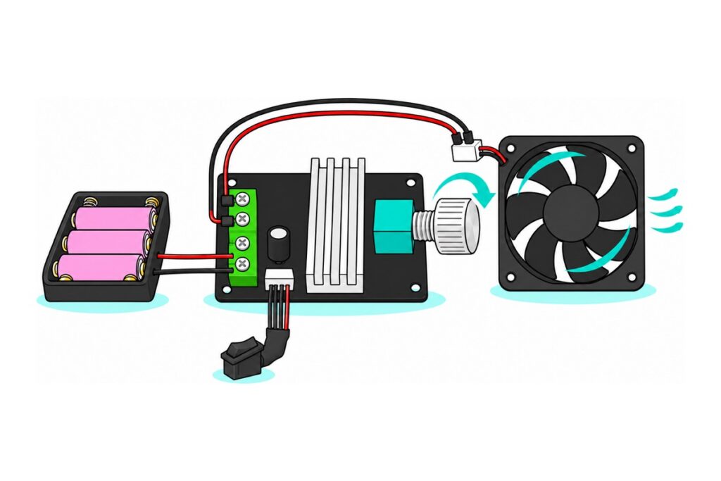
A knob-type PWM DC motor speed controller module sets a DC motor’s speed with no Arduino and no code: wire a 6–28V supply into its IN screw terminals and the motor into the motor pair, set the rocker switch to forward, and turn the knob. The board switches the supply fully on and off more than ten thousand times a second; the knob sets the fraction of on-time — the duty cycle — from 0 to 100%.
The same board goes by many names (DC motor speed controller, DC controller, PWM module, modul PWM); ours is the 3A 6–28V PWM speed controller.
How does a PWM module control DC motor speed without losing torque?
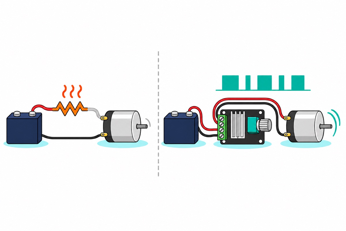
A PWM (pulse-width modulation) controller never feeds the motor a reduced voltage. Its MOSFET is either fully on — the motor sees the whole supply — or fully off, more than ten thousand times a second. The knob sets the duty cycle, the percentage of each cycle spent on: at 40% duty on 12V the motor averages 12 × 0.4 = 4.8V, and because winding inductance and rotor inertia are far too slow to follow individual pulses, it behaves as if fed a smooth 4.8V and settles near 40% speed.
The chopping is why low-speed torque survives on a brushed motor. Its torque follows winding current, set by the gap between the voltage on its terminals and the back-voltage its own spinning generates. A fully-on MOSFET drops almost nothing, so PWM holds the average at duty × supply however much current the motor pulls: load the motor, it slows, back-voltage falls, and current (torque) rises to push back. A series resistor or rheostat drops current × resistance, so the harder the motor pulls, the less voltage reaches it, and a starting motor pulls hardest of all.
Take a 12V motor with a 4Ω winding drawing 0.15A unloaded. Half speed needs about 6.3V at its terminals: PWM gives that at roughly 50% duty, and a held shaft can still pull 6.3 ÷ 4 ≈ 1.6A. A resistor set for the same half speed drops 5.7V at 0.15A, so it is 38Ω, and at start-up allows only 12 ÷ 42 ≈ 0.29A: the motor sticks, lurches and stalls while the resistor heats.
Which parts do you need for a no-code fan speed controller?
Parts list: knob-controlled 12V fan — no Arduino, no code
 3A PWM Generator Module DC Motor Speed Controller Pulse Width Modulation Adjustable Frequency 1KHz-150KHz
 DC Cooling Fan 5V/12V Brushless Small Fan for 3D Printer DIY Projects Electronics Cooling - 8025 FAN (12V)
 18650 Battery Holder 1/2/3/4 Slot 3.7V Battery Cell Housing Battery Case Battery Casing - 18650 BATTERY HOLDER (3)
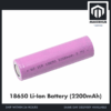 3.7V 18650 Battery Rechargeable Li-Ion Battery 1200mAh 2200mAh 3200mAh Flat Top - 18650 Li-Ion Battery (2200mAh)
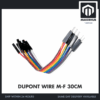 40pcs Dupont Wire 10cm 20cm 30cm for Breadboard DIY Experiment Jumper Wire Breadboard wire - DUPONT WIRE M-F 30CM
Parts list
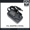 Power Supply Adapter DC Universal AC to DC Converter PSU 5V2A 5V3A 9V2A 12V2A - P.S. ADAPTOR (12V2A)
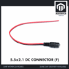 5.5x2.1mm DC Power Male Connector Plug Jack Adapter for Arduino DIY Electronics Projects - 5.5x2.1 DC CONNECTOR (F)
 XL830L Digital Multimeter with backlight Portable Multimeter Electronics Project
The wall-adapter lane for a permanent install, plus a multimeter to confirm polarity and measure your motor's real running current.
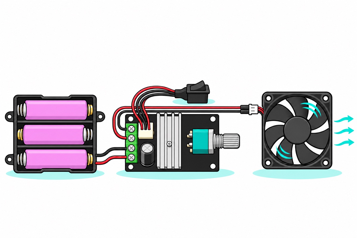
The 3A PWM module is the 6–28V, 3A, 80W class: a black PCB with a large teal potentiometer (the knurled silver knob cap ships loose — press it onto the splined shaft), a MOSFET under a finned heatsink, one green 4-way screw block, and a pre-wired three-position rocker switch for forward, off and reverse. The demo load is the 12V 80mm case fan, this module’s classic job, and its tail ends in a small white plug with two exposed pins, so male-to-female jumpers reach the screw terminals with no soldering.
The fan is brushless, with its own drive electronics in the hub, so it treats the chopped supply as a lower average voltage and simply runs slower. The torque story above belongs to brushed motors, where this module shines: an R365 12V diaphragm pump, geared motors, a model conveyor. Those draw real current: wire them with 20 AWG or thicker stranded wire, not Dupont jumpers.
For power, three 18650 cells in the 3-slot holder sit in series: 11.1V nominal, 12.6V full, about 9V depleted — all inside the 6–28V window — and the holder’s fitted red and black leads screw straight into the supply terminals. The 2200mAh cells are unprotected flat-tops, and the module has no low-battery cut-off: it is rated to keep running down to 6V — 2V a cell, deep enough to ruin them — so stop and recharge once the pack reads about 9V. Charge them properly (our TP4056 charging guide) and never mix old and new cells in one holder (the battery holder guide covers the options). The rocker’s O position stops the motor, not the board, so lift a cell out for storage. For a permanent install, the 12V 2A adapter plus a female DC jack pigtail does the same job from the wall — any 12V supply ending in bare leads works (our power supply guide explains headroom).
What this module cannot do is small motors. Its input starts at 6V, and the knob turns all the way to 100%, handing the motor that whole supply, so a 3–6V TT gearbox, N20 or mini 3–5V pump has no safe match here. Their lane is the 1.8–15V 2A PWM module, the same idea scaled down.
How do you wire the PWM speed controller module?
The 3A module’s green 4-way screw block sits on its left edge and carries both circuits: the top pair, silkscreened 电机 (“motor”), is the output, and the bottom pair, marked IN, takes the supply. The rear silkscreen runs Power−, Power+, Motor+, Motor− along the block, so the two + screws sit together in the middle and the two − screws at its outer ends. The rocker switch’s plug clicks into the white socket beside the block, and its four wires loop the motor output through the switch: the centre position (O) disconnects the motor, and I and II feed it opposite polarities, forward and reverse.
| From | To | Note |
|---|---|---|
| Holder red lead | IN Power+ (bottom pair, inner screw) |
Both + screws are the middle pair. Meter the red lead first |
| Holder black lead | IN Power− |
|
Output Motor+ (top pair, inner screw) |
Jumper 1, male pin clamped in the terminal | Red jumper for sanity |
| Jumper 1 female end | Fan plug, red-wire pin | The socket slides onto the exposed pin |
Output Motor− |
Jumper 2 → fan plug, black-wire pin | Same arrangement, black jumper |
| Rocker switch plug | White socket beside the block | O = motor off; I and II = the two directions |
Supply polarity is the one mistake that costs money. The input feeds the electrolytic capacitor and the MOSFET directly, with no reverse-polarity protection in the path. Reversed, the MOSFET’s built-in body diode and the diode across the motor output conduct in series, a near short across the supply, so swapping Power+ and Power− even briefly can kill the board. Red to Power+, black to Power−, and read the supply leads with the multimeter on DC volts before the module ever sees power. A fan only runs one way round, and one without built-in polarity protection can be damaged by reversed power, so find forward before the fan is connected: knob to full, rocker to I, meter across the motor pair. Positive at Motor+ means I is forward; negative means II.
First run: rocker to forward, knob from zero. The fan stays silent for the first third of the turn, snaps into motion around 30–40%, and scales smoothly from there — below that point the average voltage is too low for its internal electronics, which is normal for fans, not a fault. A brushed motor creeps from much lower on the dial.
How do you match the module to your motor?
The 3A PWM module publishes three numbers that must clear your motor: 6–28V input, 3A continuous, 80W. Voltage is easy — the module passes its supply through, so pick the supply for the motor’s rated voltage, inside that window. The 80W cap bites only near the top: 28V × 3A would be 84W, so above about 27V the power cap binds first — at 28V, 80 ÷ 28 ≈ 2.9A. At 12V, 3A is just 36W — current is the whole story.
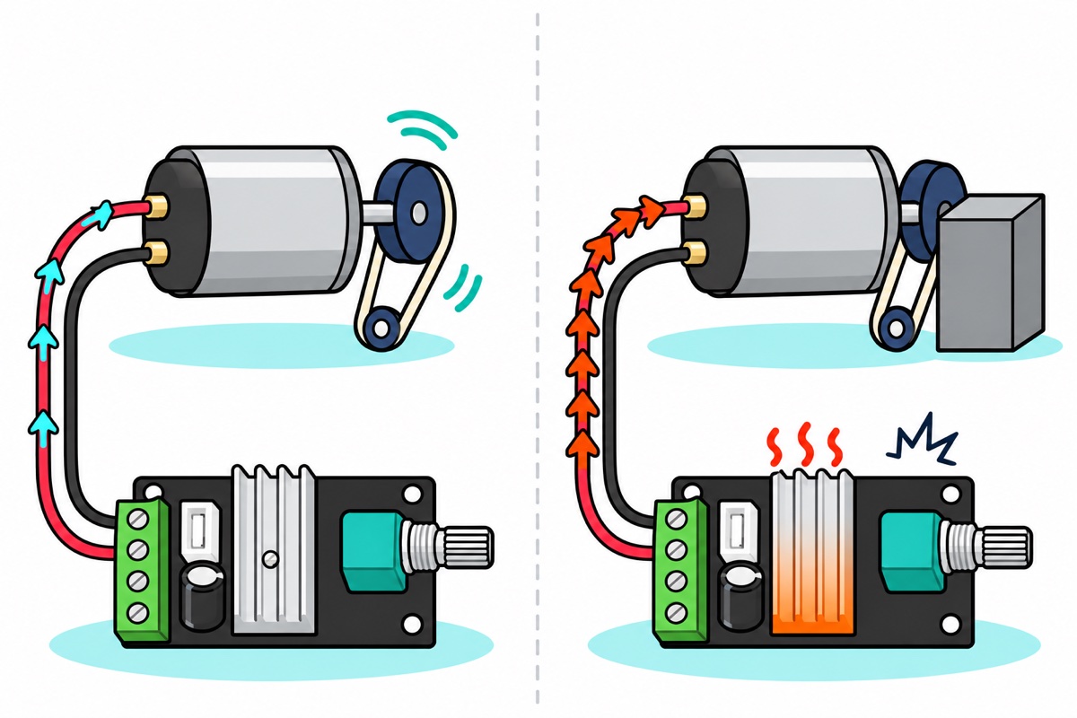
The current rating is where boards die, because the number that matters is stall, not running current. A spinning brushed motor generates a back-voltage proportional to its speed that opposes the supply, and only the small difference drives current through the winding. Jam the rotor and that back-voltage is zero: the full supply sits across the bare winding resistance — nearly a dead short — and the current jumps to typically 5–10× the running figure. A motor cruising at 0.7A can demand several amps the moment something blocks it, and that quickly overheats a 3A-rated board: heat in the MOSFET and copper rises with the square of current, so double the current is four times the heat. A cooked MOSFET usually fails shorted, locking the motor at full speed. Reversing at speed is worse: flip I to II on a spinning motor and its back-voltage adds to the supply instead of opposing it, pushing current toward twice the stall figure.
So size against stall, which you can measure without stalling anything: stall current is supply voltage ÷ winding resistance. On the multimeter’s lowest ohms range, read across the disconnected motor’s terminals, subtract the probes-touching reading, and keep the lowest value as you turn the shaft: 4Ω on 12V means 3A at stall. For running current, move the red probe to the 10A socket and splice the meter into one motor wire under real load, then move it back, or the next voltage check shorts the supply through the meter. A fan draws a fraction of an amp even when blocked; the loads that stall are geared ones: belts, wheels, winches. If stall crowds 3A, the 4.5–35V 5A module wires the same way with more headroom.
Why does the motor whine, and what does switching frequency change?
The whine comes from the motor itself. Every current pulse gives the windings a tiny magnetic kick, and when the switching frequency sits inside the audible band — human hearing tops out around 16–20 kHz — the windings and laminations vibrate like a very quiet loudspeaker at exactly that frequency. Push the switching above the band and the tone disappears; the trade is heat, because a MOSFET wastes a little energy in every transition through its half-on state, so switching losses rise with frequency.
On the 3A module that trade-off is decided at the factory: the single potentiometer adjusts duty cycle only, and the oscillator runs at a fixed frequency in the 10–20 kHz region typical of these boards, at or just under the top edge of hearing, so a thin whine from some motors at part throttle is normal and harmless here. A scope across the output is a good bench habit if the exact figure matters. A project that genuinely needs adjustable frequency wants the XY-LPWM signal generator instead — but its output is a weak signal (a few tens of milliamps at most) with no power stage, so it needs a MOSFET behind it, and our IRF520 guide covers that pairing’s gate traps.
When do you need an Arduino and a driver board instead?
The knob module’s job description is a human hand setting the speed and, with the rocker, the direction. The moment either must come from anywhere else, you have outgrown it. Reversing on command needs an H-bridge: four transistors that do the rocker’s wire-swap electronically, on a signal from a pin. Holding speed steady under changing load needs feedback — something must measure real speed and trim the duty cycle, and a potentiometer cannot read sensors.
That half is already written: our L298N motor speed control guide covers an Arduino generating the PWM and reversing through the H-bridge; the DRV8833 vs L298N comparison picks the driver. The decision: a fan, pump or conveyor that only needs a hand-set speed — the knob module. Speed or direction set by code, sensors or a schedule — a driver board and a microcontroller.
Common mistakes we see
Sizing the controller by running current. The printed figure is the happy case; a jammed rotor draws 5–10× it. Size against stall.
Reversing the supply leads. With no reverse-polarity protection, one swapped pair at IN can end the board. Meter check first.
Flipping the rocker from I to II at speed. The motor’s back-voltage joins the supply and the spike beats a stall. Pause in O until the shaft stops.
FAQ
How do I control a DC motor’s speed without an Arduino?
With a knob-type PWM speed controller module: supply into IN, motor onto the output terminals, rocker to forward, turn the knob. No code, and unlike a resistor it holds the set voltage when a brushed motor is loaded, so the motor keeps its low-speed torque. An Arduino only becomes necessary when code or sensors must set the speed or direction.
Why not just use a resistor or rheostat to slow the motor?
A resistor drops the most voltage exactly when the starting motor draws the most current, so the motor stalls while the resistor heats. PWM’s switch drops almost nothing, so the average holds steady however much current the motor draws.
Can this PWM module reverse the motor’s direction?
Yes, by hand: the rocker’s I and II positions are the two directions, and O stops the motor. Let it stop in O before flipping. Reversing from code or sensors needs an H-bridge driver like the L298N.
Will it work with a 3V–6V motor?
No — it needs at least 6V in, passes that supply to the motor, and the knob runs to 100%. For TT, N20 and other small motors, use a PWM module rated from 1.8V.
Can it control a 12V brushless case fan?
Yes — a variable-speed cooling fan is this module’s classic project. The fan’s hub electronics average the chopped supply, start around 30–40% on the knob, and control smoothly above that. Keep the rocker on the forward side.
Last updated November 2026. Stuck? Chat with us on WhatsApp.
