

Tutorials
ESP32-C3 Super Mini Getting Started: Upload, Serial Monitor and Safe Pins
Nov
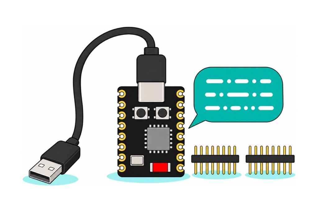
To get the ESP32-C3 Super Mini working in Arduino IDE, use a USB-C cable that carries data and choose the board Nologo ESP32C3 Super Mini. On the generic ESP32C3 Dev Module entry, set USB CDC On Boot to Enabled, or Serial Monitor stays blank. A board whose port has vanished comes back by holding BOOT while tapping RST.
The ESP32-C3 Super Mini packs 2.4GHz Wi-Fi and Bluetooth LE into 22.5×18mm but behaves unlike any ESP32 DevKit. Still deciding between a WROOM DevKit, an S3 and a C3? That choice is covered in which ESP32 to buy.
Why is the Super Mini different from a normal ESP32 DevKit?
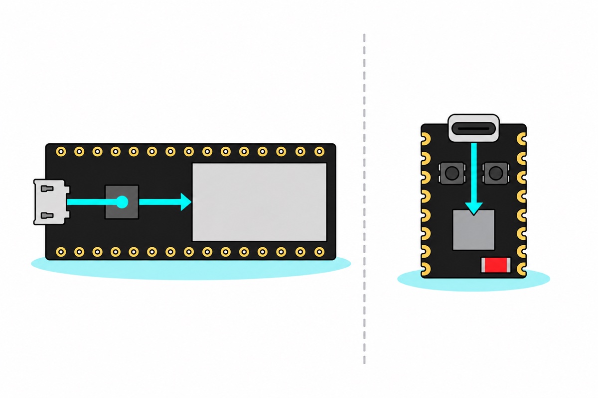
The ESP32-C3 Super Mini has no USB-to-serial chip. On a WROOM DevKit, a CP2102 or CH340 bridge sits between the USB connector and the ESP32, powered straight from the USB lead, so the COM port appears the moment you plug in and stays there whatever the ESP32 is doing — crashed, asleep, or blank. The Super Mini deletes that chip, because the C3 silicon has a USB Serial/JTAG controller built in: the USB-C connector wires almost directly into the ESP32-C3 itself.
Without the bridge, the serial port is a peripheral inside the chip, so it only exists while the chip is awake and running — deep sleep or a crashing sketch takes the port down with it. And with no bridge chip to define where serial output goes, the Arduino core must decide whether Serial means the USB link or the physical TX/RX pins — the USB CDC On Boot setting below.
Which parts do you need to get started?
Parts list: ESP32-C3 Super Mini first-time setup
 ESP32 Super Mini Ultra Small Size ESP32-C3 RISC-V Low Power Consumption - ESP32-C3 SUPER MIN
 Data Cable Type-A Type-C MicroUSB Type-B 0.5m 1m 30cm 0.3m 100cm Data Transfer Upload Code - TYPE-A TO TYPE-C CABLE (0.5M)
Parts list
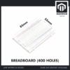 MB102 Breadboard 170 400 830 Holes Breadboard Donut Board Arduino Prototype Multi Color - BREADBOARD (400 HOLES)
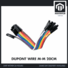 40pcs Dupont Wire 10cm 20cm 30cm for Breadboard DIY Experiment Jumper Wire Breadboard wire - DUPONT WIRE M-M 20CM
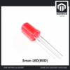 Round Head LED 3mm / 5mm / 8mm - Red/Yellow/Blue/Green/White - 5mm LED (RED)
 400 pcs 1/4W Resistor Pack Resistor Kit 20 Common Value with 20 each
For the external-LED test at the end — solder the included headers on first. Any 220–330Ω resistor from the pack works.
A USB cable carries four wires — 5V, ground, and the D+/D− data pair — and many charging cables leave the data pair out. With one of those the board powers up and looks alive, yet no port can ever appear. It is the most common cause of “board not detected”, which is why a known-good USB-A to USB-C data cable sits in the main list.
The board ships with two loose 8-pin male header strips, unsoldered — the castellated edges are also made to solder flat onto a carrier PCB, so fitting headers is left to you. Every step of this guide up to the breadboard section works without a soldering iron, since the test LED is already on the board; when you get there, our soldering basics guide covers the technique.
How do you set up Arduino IDE for the ESP32-C3 Super Mini?
In Arduino IDE, open Boards Manager, search “esp32”, and install esp32 by Espressif Systems. Then pick Tools → Board → esp32 → Nologo ESP32C3 Super Mini, plug the board in, and select the new port under Tools → Port (COMx on Windows, /dev/cu.usbmodem… on Mac). If that entry is missing, update the esp32 package. No driver is needed: the C3’s USB is a standard serial device Windows, macOS and Linux already support, so CH340 or CP2102 drivers do nothing here.
The Tools menu setting USB CDC On Boot decides where Serial goes: Enabled maps it to the USB link (CDC is the USB class that behaves like a serial port), Disabled maps it to the hardware UART on pins 21 and 20. Disabled, your sketch runs and prints happily — out through two physical pins nothing is connected to — and Serial Monitor shows nothing. The Nologo ESP32C3 Super Mini entry’s USB CDC On Boot menu offers only Enabled, so it cannot be set wrong; the generic ESP32C3 Dev Module entry defaults it to Disabled, the usual cause of “ESP32-C3 Serial Monitor not working”. Uploads still work with it Disabled, since the uploader talks to the boot ROM, not your sketch, so the board looks healthy while printing nothing.
What is the first sketch to upload?
// ESP32-C3 Super Mini first-run test: onboard LED + USB serial
const int LED_PIN = 8;  // onboard LED = GPIO8 (correct under either board entry)

void setup() {
  Serial.begin(115200);  // over native USB the number is ignored - any value works
  pinMode(LED_PIN, OUTPUT);
}

void loop() {
  digitalWrite(LED_PIN, LOW);   // onboard LED is wired to 3.3V, so LOW = ON
  Serial.println("LED on");
  delay(500);
  digitalWrite(LED_PIN, HIGH);  // HIGH = off
  Serial.println("LED off");
  delay(500);
}
Click Upload. Normally the C3’s USB controller resets the chip into upload mode itself, the job a DevKit’s auto-reset transistors do, but only through a live port; if the upload fails or the port is gone, use the BOOT trick below. Once it is running, open Serial Monitor — at any baud rate: over native USB there is no baud clock to match, so the mismatched-baud garbage a DevKit can show is impossible here.
Notice the LED logic is inverted. The onboard LED sits between the 3.3V rail and GPIO8, so the pin lights it by sinking current: writing LOW completes the circuit — a backwards-looking blink is the wiring, not a fault. Lines printed in the first instant after reset can also be lost while the PC re-attaches, so if a one-shot print from setup() never appears, add delay(1000); first. Do not swap in while (!Serial); — on the C3 it waits for a listening PC, so on a phone charger the sketch never starts.
Why did the COM port vanish, and how does BOOT bring it back?
When the Super Mini’s COM port vanishes mid-session, DevKit instincts say the board died. It almost never has: the port lives inside the C3, so anything that stops the chip running normally — deep sleep, a crash-and-reboot loop, code that reconfigures the USB pins — takes the port off your PC with it.
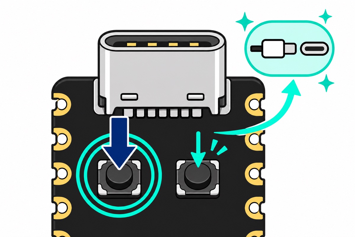
The way back in is the two tiny buttons under the USB connector: hold BOOT (the left one), tap RST, then release BOOT. BOOT is wired to GPIO9, a strapping pin — one whose level the boot ROM reads at the instant reset is released to decide how to boot. GPIO9 low at that instant sends the chip into the ROM’s download mode instead of your sketch; the download ROM keeps the USB port alive and waits, so you get a stable port whatever the previous sketch was doing. If the new sketch does not start by itself afterwards, tap RST once.
A sketch that sleeps or crashes the moment it boots needs nothing more: in download mode it never runs, so the upload replaces it completely. What a normal upload leaves behind is stored data — saved Wi-Fi credentials, Preferences, files. If a fresh sketch still misbehaves because of that, enable Erase All Flash Before Sketch Upload (Tools menu) for one upload: the whole flash is wiped before the new sketch lands. Set it back to Disabled after, or every upload wipes that data again.
ESP32-C3 Super Mini pinout: which GPIOs are safe to use?
The Super Mini exposes thirteen GPIOs — 0 to 10, 20 and 21 — plus 5V, 3.3V and G. The 5V pin carries USB power and feeds the onboard regulator, so never feed it from a second supply while USB is plugged in: the two would push current into each other. Every GPIO is strictly 3.3V logic, so a 5V sensor output wired straight to a pin can damage the chip; power the sensor from 3.3V, or divide its output with 10kΩ in series and 20kΩ from the pin to G (5V becomes 3.3V).
| Pins | Role on this board | Watch out |
|---|---|---|
| 0, 1, 3, 4 | Analog A0/A1/A3/A4 (ADC1) + general I/O | First choice for analog and general use |
| 2 | Analog A2 (ADC1) + general I/O | Strapping pin — keep it HIGH at reset (Espressif recommends a pull-up) |
| 5 | General I/O (the core still labels it A5) | On ADC2, which the Arduino core disables on the C3 (chip erratum) — analogRead(5) returns 0; use 0–4 for analog |
| 6, 7, 10 | General I/O (6/7 are default SPI MOSI/SS; SCK/MISO are 4/5) | Clean digital pins |
| 8 | Onboard LED, default I2C SDA | Strapping pin; LED shares the pin |
| 9 | BOOT button, default I2C SCL | Strapping pin; LOW at reset = bootloader |
| 20, 21 | UART0 RX/TX | Become Serial if USB CDC is disabled; with it enabled, a UART module here is Serial0 |
The ESP32-C3‘s strapping pins are GPIO2, 8 and 9. After boot they work as ordinary pins — the risk is only at reset, when a module that drags one the wrong way can stop the board booting or drop it into the bootloader — so hang nothing on 2, 8 or 9 that pulls hard at power-up.
One collision to know: the default I2C pins are SDA = 8 and SCL = 9 — the LED pin and the BOOT button. Left there, the LED flickers with bus traffic and pressing BOOT grounds the clock line. The fix is one line, because the ESP32 core lets I2C sit on any pins: Wire.begin(6, 7); moves SDA to 6 and SCL to 7, two clean pins, before any I2C library runs. If you also use SPI (default pins 4 to 7), use Wire.begin(0, 1); instead.
How do you blink an external LED on a breadboard?
Solder the headers long pins down, button side up, with both strips pressed into the breadboard to hold them straight. Once they are on, the Super Mini’s male pins plug straight into a 400-hole breadboard with the board straddling the centre channel (how a breadboard works explains the hidden rows). The classic first circuit is one red LED and a resistor from the resistor pack on a safe pin — GPIO3: no strapping duty, no bus defaults. Count to find it: GPIO3 is the fifth hole down the edge that starts 5V, G, 3.3. The third hole is 3.3V; a resistor there keeps the LED lit whatever the sketch does.
A red LED drops about 2V, leaving 3.3 − 2 = 1.3V across the resistor, so 330Ω passes 1.3 ÷ 330 ≈ 4mA — clearly visible and far below what the pin can safely source. Anything from 220Ω (≈6mA) to 330Ω in the pack is fine; on these blue five-band resistors, 330Ω reads orange-orange-black-black-brown and 220Ω red-red-black-black-brown.
| From | To | Note |
|---|---|---|
| Super Mini pin 3 | Resistor leg 1 (same breadboard row) | 220–330Ω, either way round |
| Resistor leg 2 | LED long leg (anode), shared row | Long leg = positive |
| LED short leg | Blue − rail, then M-M jumper from the − rail to the board’s G pin | Short leg = cathode |
Change one line in the sketch — const int LED_PIN = 3; — and upload. The external LED now blinks opposite to the printed messages, and that is the lesson: this LED runs from the pin through to ground, so HIGH lights it, while the onboard LED hangs from 3.3V, so LOW lights that one.
What can a WROOM DevKit do that the Super Mini cannot?
The Super Mini’s honest limits: the C3 is a single-core RISC-V chip at 160MHz with 4MB flash, against the WROOM’s dual-core 240MHz, and thirteen GPIOs against twenty-five-plus. There is no classic Bluetooth: the C3 carries a BLE 5.0 radio only, so BLE sensors and phone apps work, but streaming audio to a speaker (A2DP) or legacy serial-over-Bluetooth does not — that hardware is not on the chip. There are also no DAC or touch pins: a WROOM sketch that calls touchRead() will not even compile. For Wi-Fi sensor nodes and most IoT project ideas none of this matters and the tiny footprint wins; when it does, which ESP32 to buy walks through the choice.
Common mistakes we see
Blaming the board when no port appears. It is nearly always a charge-only cable with no data wires; swap to a known data cable first.
Picking ESP32C3 Dev Module and getting a silent Serial Monitor. That entry defaults USB CDC On Boot to Disabled, so prints go to pins 21/20 instead of USB. Pick Nologo ESP32C3 Super Mini, or enable CDC.
Declaring a deep-sleep board dead. The port vanishing after a deep-sleep upload is the sketch working. Hold BOOT, tap RST, and it is back.
FAQ
Why is my ESP32-C3 Super Mini not showing anything in Serial Monitor?
Almost always the USB CDC On Boot setting. Disabled, Serial prints go to the hardware UART pins (21/20), not USB. Select the board Nologo ESP32C3 Super Mini (CDC always enabled there) or set Tools → USB CDC On Boot → Enabled, re-upload, and reopen Serial Monitor.
Why does no COM port appear when I plug the board in?
Usually the cable: charge-only USB-C leads have no data wires, so the board powers up but can never enumerate. If a known data cable still shows no port, hold BOOT and tap RST — a crashed or sleeping chip takes its port down, and the ROM bootloader brings it back.
How do I put the ESP32-C3 Super Mini into upload mode manually?
Hold the BOOT button (GPIO9), tap RST, then release BOOT. The boot ROM reads GPIO9 low at reset and enters download mode, where the USB port stays alive and uploads always work.
Does the ESP32-C3 Super Mini support classic Bluetooth?
No. The C3 has a Bluetooth LE 5.0 radio only — BLE apps and sensors work, but classic-Bluetooth jobs like audio streaming (A2DP) or legacy serial (SPP) need the original ESP32, as on a WROOM-32 DevKit — the ESP32-S3 is BLE-only too.
Last updated November 2026. Stuck? Chat with us on WhatsApp.
