

Tutorials
Arduino IR Remote Control with HX1838: Decode Buttons and Fix the Library
Aug
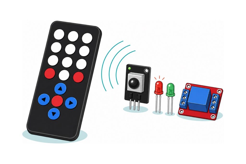
An IR remote project is three wires and one library. The HX1838 receiver’s signal pin goes to any Arduino digital pin, the IRremote library hands you a number for every button press, and your sketch is a switch on that number. Almost every “my Arduino IR remote code doesn’t work” turns out to be a library-version problem: Library Manager installs 4.x today, and sketches written for 2.x use an API that has been replaced.
What parts does an Arduino IR remote project need?
The HX1838 IR remote set is the whole receiving half in one bag: a 17-key matte-black remote, the receiver breakout on its small black PCB, a four-wire dupont lead, and a water-clear IR emitter LED for later. Everything else is payload — two LEDs to prove decoding works, a relay to prove it can switch something.
Parts list — IR remote control with Arduino and the HX1838 kit
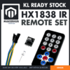 HX1838 IR Remote Control Set Infrared Receiver Module Kit with Remote Controller for Arduino Pi DIY Projects
 Arduino Compatible UNO R3 FT232 Development Board Arduino Compatible CH340 Alternative
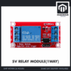 Relay Module 3.3V 5V 12V 1/2/4/8 Ways Optocoupler Trigger Relay Module 1 2 4 8 Channel Relay Module - 5V RELAY MODULE(1WAY)
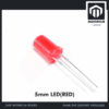 Round Head LED 3mm / 5mm / 8mm - Red/Yellow/Blue/Green/White - 5mm LED (RED)
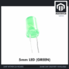 Round Head LED 3mm / 5mm / 8mm - Red/Yellow/Blue/Green/White - 5mm LED (GREEN)
 400 pcs 1/4W Resistor Pack Resistor Kit 20 Common Value with 20 each
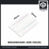 MB102 Breadboard 170 400 830 Holes Breadboard Donut Board Arduino Prototype Multi Color - BREADBOARD (400 HOLES)
 40pcs Dupont Wire 10cm 20cm 30cm for Breadboard DIY Experiment Jumper Wire Breadboard wire - DUPONT WIRE M-M 20CM
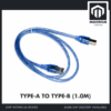 Data Cable Type-A Type-C MicroUSB Type-B 0.5m 1m 30cm 0.3m 100cm Data Transfer Upload Code - TYPE-A TO TYPE-B (1.0M)
Optional — starting from zero
| Item | Price | Qty | |
|---|---|---|---|
 Electronic Component Set Beginner Electrical Learning Kit For Arduino Beginner Learning - ELECTRICAL STARTER KITELECTRK Electronic Component Set Beginner Electrical Learning Kit For Arduino Beginner Learning - ELECTRICAL STARTER KITELECTRK | RM39.95 |
The electrical starter kit already contains a breadboard, dupont jumpers, assorted LEDs and a resistor assortment, so a reader building a first bench can take this box instead of the breadboard, jumper, LED and resistor rows above.
Connector gender decides whether the parts fit together. The lead in the kit has a female socket at each end, so it mates the receiver’s pins to a pin-header board such as a Raspberry Pi, but it has nothing to grip on an Uno, whose headers are female too. The receiver breakout’s three pins are male at 2.54 mm, so instead it pushes straight into the 400-hole breadboard; from there to the Uno‘s female sockets every wire is male-to-male, and the same pack reaches the relay module, whose screw terminals clamp a bare male pin. One M-M pack covers the build. The Uno programs through a full-size USB-B socket and ships without a lead, so add the A-to-B cable.
Each LED needs a series resistor, and the value is arithmetic rather than folklore. An Arduino output pin sits at about 5 V and a red 5 mm LED drops roughly 2.0 V, so 220 Ω passes (5 − 2.0) / 220 ≈ 14 mA — bright, and well under the 40 mA the ATmega328P datasheet gives as the absolute maximum for one I/O pin. The green LED is the same sum in a second colour. Any 220 Ω resistor from a drawer will do; the resistor pack and the starter kit both carry them.
Which Arduino IR remote library do you install?
The IRremote library — Ken Shirriff’s original, maintained since by Armin Joachimsmeyer — is the one this guide uses. Install it from inside the IDE: Sketch → Include Library → Manage Libraries, type IRremote, and press Install on that entry. Take it from Library Manager rather than a ZIP linked in a forum post, because a ZIP is frozen at whatever version was current the day that page was written — which is exactly how people end up running 2.x code against 4.x documentation. Searching that word also surfaces IRremoteESP8266, a different library with a different API written for ESP boards, so check that the entry you install is plain IRremote.
Why does my Arduino IR remote code not work any more?
The IRremote library rewrote its receiving API at version 3 and kept that shape through 4.x, so a sketch copied from a 2.x-era blog and today’s Library Manager download are two different vocabularies. In 2.x you created your own receiver object and passed a results struct into decode(). From 3.x onward there is one global IrReceiver, decode() takes no argument, and the frame lands in IrReceiver.decodedIRData.
| What the sketch does | IRremote 2.x | IRremote 4.x |
|---|---|---|
| Header | #include <IRremote.h> |
#include <IRremote.hpp> |
| Create the receiver | IRrecv irrecv(2); |
Nothing — IrReceiver already exists |
| Hold the result | decode_results results; |
Nothing — use IrReceiver.decodedIRData |
| Start receiving | irrecv.enableIRIn(); |
IrReceiver.begin(2, ENABLE_LED_FEEDBACK); |
| Test for a frame | if (irrecv.decode(&results)) |
if (IrReceiver.decode()) |
| Read the button | results.value (32 bits, MSB first) |
IrReceiver.decodedIRData.command |
| Detect a held button | results.value == 0xFFFFFFFF |
flags & IRDATA_FLAGS_IS_REPEAT |
| Wait for the next frame | irrecv.resume(); |
IrReceiver.resume(); |
What you see depends on which header the old sketch keeps, and neither symptom announces itself as a version problem. Leave #include <IRremote.h> in place and 4.x still compiles, because the library ships a backward-compatibility stub for exactly this case. That stub emits seven compiler warnings and fills only three fields — value, bits and decode_type. It also prints an eighteen-line upgrade notice straight into your Serial Monitor where you expected a hex code, and it does that on the first call to decode(), before you have pressed a button. Change the include to #include <IRremote.hpp> and leave the 2.x code alone, and the compiler is satisfied but the linker is not: undefined reference to 'IRrecv::decode(decode_results*)', because the argument-taking decode() has no body outside that stub.
Two fixes are honest. Migrate the sketch using the table above — the only route that also gives you the protocol name, the address and the repeat flag. Or pin the old library on purpose: in Library Manager select IRremote, open the version dropdown and install 2.6.0, the version its own message points at. That suits a project you would rather not disturb, but it is a poor default, because everything you read next is written for 4.x. If you would rather watch the rewrite than read it, this walkthrough migrates a 2.x sketch line by line — the same change 4.x still expects:
How do you find your own remote’s button codes?
The HX1838 receiver does the hard part before your sketch sees anything. The remote’s emitter flashes a 38 kHz carrier; the shielded module amplifies only that frequency, strips the carrier away and puts a clean logic level on the S pin, low while the carrier is present. That narrow filtering is what stops daylight registering as button presses.
Riding on the carrier is the NEC protocol, which almost every kit remote of this type uses. A press opens with a 9 ms burst and a 4.5 ms gap, then sends 32 bits, each a 560 µs burst followed by a gap of 560 µs for a zero or 1690 µs for a one. Those 32 bits are four bytes: an address, that address inverted, the command, the command inverted. The inverted copies are the protocol’s own check bytes, which is why a decoded frame is either right or absent rather than quietly wrong. IRremote uses that check to tell the variants apart as well: when a command and its inverse disagree it reports the frame as Onkyo with a 16-bit command, so a protocol name other than NEC is not a fault.
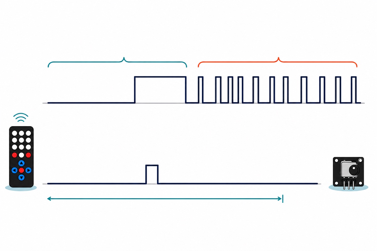
A hex table copied from another page will not match your remote, and may not match your own earlier printout either. Two things differ. Remote models carry different addresses and commands. But the same press also prints differently between library versions, because 2.x reported the whole 32-bit word MSB first as one number while 4.x reports address and command separately, LSB first. Take a 2.x value of 0x00FFA25D: its bytes are 0x00, 0xFF, 0xA2, 0x5D — address, inverted address, command 0xA2, inverted command 0x5D. Reverse the bits of 0xA2 (1010 0010) and you get 0100 0101, which is 0x45 — exactly what 4.x prints for that same press. One button, three numbers in circulation. Print your own table.
Holding a button down does not resend the frame. The remote sends a short repeat instead — the same 9 ms burst, a shorter 2.25 ms gap, one closing 560 µs mark, no data — every 110 ms until you let go. Version 2.x surfaced that as the sentinel 0xFFFFFFFF, the origin of every if (results.value == 0xFFFFFFFF) line you have seen. Version 4.x sets IRDATA_FLAGS_IS_REPEAT in decodedIRData.flags and copies the previous address and command in, so the command stays readable and the choice is yours: ignore repeats for a toggle, act on them for hold-to-dim.
Field in decodedIRData |
What it holds | What you do with it |
|---|---|---|
protocol |
NEC, SONY, RC5… or UNKNOWN |
UNKNOWN usually means a weak or partly blocked signal |
address |
Which remote sent it | Constant for every button on one remote — ignore it, or use it to reject the neighbour’s TV remote |
command |
Which button was pressed | This is the number your switch compares against |
flags |
Bit field, including IRDATA_FLAGS_IS_REPEAT |
Test it to tell one press from a held button |
How do you wire the IR remote receiver, the LEDs and the relay?
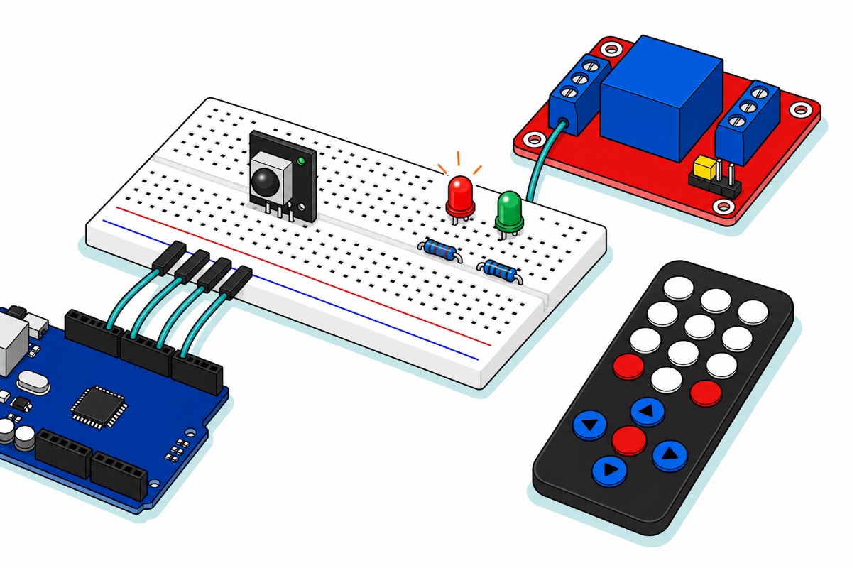
The HX1838 receiver breakout carries its pin names in white silkscreen: S on one edge, − on the opposite edge, unmarked VCC in between. The order is S, VCC, GND, so the supply sits in the middle — a module inserted backwards puts 5 V where ground should be.
The 1WRELAY module’s control side is not a pin header; it is a blue three-way screw terminal marked IN, DC− and DC+. An optocoupler stands between that terminal and the coil, which changes what your Arduino pin is doing: it does not drive the relay coil. It lights a small LED inside the black optocoupler chip, a phototransistor facing that LED switches a transistor, and the transistor lets the 5 V rail push current through the coil. The Songle SRD-05VDC-SL-C’s coil is specified at about 70 Ω, so 5 V pushes roughly 70 mA through it — several times what you want out of one GPIO pin, and exactly why DC+ must go to 5 V rather than be left empty.
What the optocoupler separates is the pin from the coil’s current, not one supply from another: DC+ here is the Uno’s own 5 V. That is still the point, because one relay plus two lit LEDs comes to roughly 100 mA, which USB power carries without complaint — it is multi-channel relay boards, with several coils pulling at once, where a separate 5 V supply starts to matter. If your project already runs a 12 V rail, the same board family comes in a 12 V coil version.
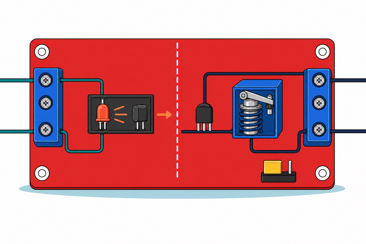
The three-pin header near the board’s lower edge, with its shunt cap bridging two of the three pins, selects trigger polarity, and it does so by moving one end of that same optocoupler LED. On H the far side of the LED is tied to DC−, so your pin completes the loop by going HIGH and sourcing a few milliamps into it. On L the far side is tied to DC+ instead, so the identical LED lights when your pin goes LOW and sinks that current. Neither the coil nor the contacts change — only which pin level closes the circuit, which is why a relay that behaves backwards is a jumper position and not a bug in your sketch. The sketch below assumes H.
On the other side of the board the contacts are a bare mechanical switch: COM and NO carry no power of their own, so the load must bring its own supply into the loop — supply positive to COM, NO out to the load, load back to that supply’s negative. NC is the same switch inverted, closed until the relay pulls in. Keep that loop low-voltage DC here, and our relay module safety guide covers what changes when mains is involved.
Start the assembly with the rails rather than the parts. The Uno offers one 5 V socket and three GND sockets, while this build wants 5 V in two places (the receiver and the relay’s DC+) and a ground return in four (the receiver, both LED cathodes and DC−). So run one male-to-male jumper from Uno 5V to the red stripe along the breadboard’s edge and another from GND to the blue stripe, then feed everything from those two rails. Every hole along a rail is the same node, so the rail becomes the junction the Uno’s header cannot provide.
| From | To | Why |
|---|---|---|
| Uno 5V | Breadboard red rail | One 5 V socket on the Uno, two things to feed from it |
| Uno GND | Breadboard blue rail | Three GND sockets on the Uno, four returns to bring home |
Receiver S |
Uno D2 | The demodulated signal — any digital pin works |
| Receiver middle pin | Breadboard red rail | Supply. It sits between S and −, so read the silkscreen first |
Receiver − |
Breadboard blue rail | Ground reference |
| Uno D4 → 220 Ω → red LED long leg | LED short leg → blue rail | The long leg is the anode; ≈14 mA through the resistor |
| Uno D5 → 220 Ω → green LED long leg | LED short leg → blue rail | Same arrangement, second colour |
| Uno D7 | Relay IN screw terminal | Drives the optocoupler LED only |
| Breadboard red rail | Relay DC+ screw terminal | Supplies the ~70 mA coil current |
| Breadboard blue rail | Relay DC− screw terminal | Return path for the coil |
| Load’s own supply → COM, load → NO | Low-voltage DC only | Open until the relay pulls in; the contacts carry no power themselves |
What does the complete Arduino IR remote code look like?
This Arduino IR remote sketch does both jobs, so there is no throwaway first upload: every decoded frame prints its protocol, address and command, and three commands are wired to actions. Upload, open the Serial Monitor at 9600 baud, press your buttons, copy the printed values into the three constants at the top, upload again.
// IR remote control with Arduino: decode your own buttons, then use them.
// HX1838 receiver + 17-key remote, two LEDs and a 1-channel relay module.
// Written for IRremote 4.x (IrReceiver / decodedIRData). Old 2.x sketches
// use IRrecv + decode_results and will NOT behave the same - see above.

#include <IRremote.hpp>   // note the .hpp - this is the 4.x header

// ---- Pins ----
// Any digital pin works for the receiver: on an Uno the library samples the
// pin from a Timer2 interrupt, not from an external-interrupt pin.
const uint8_t IR_RECEIVE_PIN = 2;
const uint8_t LED_RED_PIN    = 4;
const uint8_t LED_GREEN_PIN  = 5;
const uint8_t RELAY_IN_PIN   = 7;   // relay jumper on H = HIGH switches it on

// ---- YOUR remote's numbers ----
// Run this sketch once, watch the Serial Monitor, press the three buttons you
// want, and copy the "Command" values printed for them into these three lines.
// The values below are only placeholders - do not assume they match your kit.
const uint16_t CMD_RED   = 0x45;
const uint16_t CMD_GREEN = 0x46;
const uint16_t CMD_RELAY = 0x40;

bool relayOn = false;

void setup() {
  pinMode(LED_RED_PIN, OUTPUT);
  pinMode(LED_GREEN_PIN, OUTPUT);
  pinMode(RELAY_IN_PIN, OUTPUT);
  digitalWrite(RELAY_IN_PIN, LOW);      // start with the relay released

  Serial.begin(9600);
  IrReceiver.begin(IR_RECEIVE_PIN, ENABLE_LED_FEEDBACK);
  Serial.println(F("Ready. Point the remote at the receiver and press a button."));
}

void loop() {
  // decode() is false until a whole frame has arrived and been understood.
  if (!IrReceiver.decode()) {
    return;
  }

  // Everything the frame carried lives in this one struct.
  const uint16_t command  = IrReceiver.decodedIRData.command;
  const uint16_t address  = IrReceiver.decodedIRData.address;
  const uint8_t  flags    = IrReceiver.decodedIRData.flags;
  const bool     isRepeat = (flags & IRDATA_FLAGS_IS_REPEAT) != 0;

  // Hand the receiver back immediately so the next frame is not missed
  // while we are still printing.
  IrReceiver.resume();

  if (IrReceiver.decodedIRData.protocol == UNKNOWN) {
    // Not a protocol this build knows: usually a weak signal, sunlight,
    // or a remote using a protocol that has been switched off.
    Serial.println(F("Unknown frame - move closer and try again."));
    return;
  }

  // This is your button table. Write down what each button prints.
  Serial.print(F("Protocol: "));
  Serial.print(IrReceiver.getProtocolString());
  Serial.print(F("  Address: 0x"));
  Serial.print(address, HEX);
  Serial.print(F("  Command: 0x"));
  Serial.print(command, HEX);
  if (isRepeat) {
    Serial.print(F("  (repeat - button still held)"));
  }
  Serial.println();

  // A held button sends a short repeat frame roughly every 110 ms. Ignoring
  // repeats turns "held down" back into one press, which is what a toggle wants.
  if (isRepeat) {
    return;
  }

  switch (command) {
    case CMD_RED:
      digitalWrite(LED_RED_PIN, !digitalRead(LED_RED_PIN));
      break;
    case CMD_GREEN:
      digitalWrite(LED_GREEN_PIN, !digitalRead(LED_GREEN_PIN));
      break;
    case CMD_RELAY:
      relayOn = !relayOn;
      digitalWrite(RELAY_IN_PIN, relayOn ? HIGH : LOW);
      Serial.println(relayOn ? F("Relay ON") : F("Relay OFF"));
      break;
    default:
      // Any other button: decoded and printed, but not wired to anything yet.
      break;
  }
}
As written it compiles to 9,408 bytes, 29% of the Uno’s flash, because IRremote enables every protocol decoder it owns. Once the Serial Monitor confirms the protocol is NEC, add #define DECODE_NEC above the include and the same sketch drops to 4,614 bytes, 14% — nearly 5 kB back for one line.
Common mistakes we see from real customers
The Serial Monitor fills with paragraphs of English instead of a code. Sketch and wiring are fine; that is the 2.x compatibility stub introducing itself the first time the sketch calls decode(), which happens before you press anything. Change the header.
Nothing happens at all, from any button. Slide the battery tray out first: remotes ship with a clear plastic tab isolating the cell for transit, and it has to come out. Then let the board split the problem for you. ENABLE_LED_FEEDBACK in IrReceiver.begin() makes the library flicker the Uno’s built-in pin-13 LED while an infrared signal is coming in, so if that LED flickers as you press, the remote, the receiver and the wiring are all doing their job and the problem lies downstream in decoding or in your switch; if it stays dark, nothing is reaching the pin at all — check the receiver’s middle pin is really on 5 V and that its dome lens faces you rather than the breadboard.
IR worked, then stopped after I added a buzzer or a motor. On an Uno the IRremote receiver samples its pin from Timer2 — the same timer tone() takes over, and the same timer behind PWM on pins 3 and 11. So tone() silently kills reception until IrReceiver.restartTimer() follows it, and analogWrite() on pin 3 or 11 does the same. Move PWM loads to pins 5, 6, 9 or 10.
Buttons register twice, or a menu jumps two steps. Repeat frames are being read as fresh presses. A press held for even a fifth of a second sends one frame plus a repeat or two behind it, 110 ms apart, so test IRDATA_FLAGS_IS_REPEAT and return early, as the sketch above does. Papering over it with a delay(200) appears to work and then starts losing genuine presses: the library holds one frame at a time, so the delay lets a stale repeat take that slot while the real second press arrives behind it with nowhere to land.
FAQ
Which IRremote library version should I install?
Install the current 4.x and write 4.x code. Choose 2.6.0 only to keep an old project alive — the library’s own message names that version, and Library Manager’s version dropdown installs it.
Why does my sketch say “undefined reference to IRrecv::decode(decode_results*)”?
You have 2.x code including the 4.x header. IRremote.hpp has no argument-taking decode(); it exists only in the old IRremote.h stub. Migrate to IrReceiver and decodedIRData, or install 2.6.0.
Why do the hex codes I found online not match my remote?
Two reasons stack. Remote models differ, and library versions print the same press differently — 2.x showed the full 32-bit word MSB first, 4.x shows an 8-bit command LSB first. Print your own table.
Can the HX1838 kit also send IR signals?
Yes. The water-clear 5 mm LED in the bag is an emitter, and the same library sends with IrSender.sendNEC(). Drive it through a resistor and you can replay decoded codes — the basis of a universal remote, and a cousin of voice and Bluetooth switching.
Last updated August 2026. Stuck? Chat with us on WhatsApp.
