

Tutorials
NRF24L01 Arduino Code: Transmitter, Receiver and the Capacitor Fix
Aug
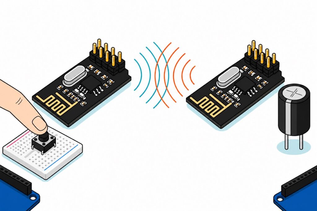
Two Arduinos talk over a pair of nRF24L01 modules in about an hour: wire both modules identically, give both ends the same five-byte address, and run one sketch that writes and one that listens. The step most builds skip is a 10–100 µF capacitor across each module’s own VCC and GND pins — without it the radio answers on SPI and still delivers nothing.
What do you need to link two Arduinos wirelessly?
The nRF24L01 module is a transceiver, not a transmitter — the same board sends and receives, so a link needs two of them and two boards to drive them. The button sits on the transmitting node only, and the receiving node reports over Serial until you give it something to switch. Both nodes get a breadboard, though — that is where each module’s capacitor bridges VCC to GND.
Parts list — a two-node nRF24L01 link between two Arduino Unos
 High Performance NRF24L01 RF Wireless Transceiver Module Antenna 2.4Ghz 1100m - NRF24L01 RF MODULE
 Arduino Uno Compatible SMD UNO R3 with Type B Cable - ATMEGA328P with CH340G-Microcontroller Project
 40pcs Dupont Wire 10cm 20cm 30cm for Breadboard DIY Experiment Jumper Wire Breadboard wire - DUPONT WIRE M-F 20CM
 40pcs Dupont Wire 10cm 20cm 30cm for Breadboard DIY Experiment Jumper Wire Breadboard wire - DUPONT WIRE M-M 20CM
 MB102 Breadboard 170 400 830 Holes Breadboard Donut Board Arduino Prototype Multi Color - BREADBOARD (400 HOLES)
 Tactile Button Momentary Switch 6mm x 6mm x 5mm Push Button 4 Pin
Optional — range upgrade, a real load to switch, and the capacitor
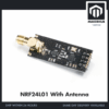 High Performance NRF24L01 RF Wireless Transceiver Module Antenna 2.4Ghz 1100m - NRF24L01 + ANTENNA
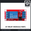 Relay Module 3.3V 5V 12V 1/2/4/8 Ways Optocoupler Trigger Relay Module 1 2 4 8 Channel Relay Module - 5V RELAY MODULE(1WAY)
 Electronic Component Set Beginner Electrical Learning Kit For Arduino Beginner Learning - ELECTRICAL STARTER KIT
The antenna version is a range upgrade for BOTH ends, never one: auto-acknowledgement means the far node transmits too, so a single upgraded end is still limited by the other. The relay module gives the receiving node something to switch. The capacitor this build needs is a 10–100 µF electrolytic — the starter kit is where to find one, since it carries both ceramic and electrolytic capacitors along with resistors, LEDs and a breadboard.
The eight pins stand in a 2×4 double row, so the nRF24L01 cannot sit in a breadboard — the two rows would land on the same tie strips and short together. Male-to-female jumpers are what fits: the female end grips the module’s pins, the male end enters the Uno‘s sockets. Male-to-male jumpers wire the button on the breadboard, and their bare pins clamp into the relay’s screw terminals. The FT232 Uno suits a PC that fights CH340 drivers.
How do you wire the nRF24L01 to an Arduino Uno?
The nRF24L01 speaks SPI, so three of its pins land on the Uno’s fixed SPI pins and cannot move; CE and CSN are ordinary outputs, chosen by convention. Pin 1 is the one with the square solder pad underneath. Both nodes are wired identically — roles are decided in software.
| Module pin | Uno pin | What it does |
|---|---|---|
| 1 GND | GND |
Ground, shared with the capacitor’s negative leg |
| 2 VCC | 3V3 |
3.3 V only. 5 V here destroys the chip |
| 3 CE | D9 |
Chip enable — puts the radio on air. Any free pin |
| 4 CSN | D10 |
SPI chip select. Any free pin |
| 5 SCK | D13 |
SPI clock. Fixed |
| 6 MOSI | D11 |
Uno to module. Fixed |
| 7 MISO | D12 |
Module to Uno. Fixed |
| 8 IRQ | leave open | Interrupt output. These sketches poll instead |
The supply pin and the logic pins follow different rules, and mixing them up is what kills modules. The Nordic datasheet puts VDD between 1.9 V and 3.6 V absolute, so the Uno’s 5 V rail is about 40% over maximum. The digital pins are separately rated to 5.25 V, which is why an Uno drives CE, CSN, SCK and MOSI straight in with no level shifter. Supply from 3V3, signals from the 5 V logic pins: both are correct at once.
The tactile button is the only other wiring, and it hides a trap: its four legs are two joined pairs, the two on each side of the body permanently connected inside it. Sit it across the breadboard’s centre channel so one pair lands in each half, then take one leg to D2 and the diagonally opposite leg to GND — diagonal is always the switching pair. A quarter turn and each joined pair bridges the channel by itself, which reads as a button held down forever. INPUT_PULLUP holds D2 high through a resistor inside the ATmega, so no external resistor is needed.
Seeing two boards actually pass a message helps before you commit:
Why is the nRF24L01 not working, and how does the capacitor fix it?
The nRF24L01’s classic failure has a signature: radio.begin() succeeds, the module reports its registers back correctly, and radio.write() still returns false every time. SPI is happy and the radio is not — which says the wiring is right and the supply is failing only during the microseconds the radio is on air.
Idling in standby the chip draws 22 µA, or 26 µA on the nRF24L01+; transmitting at 0 dBm it draws 11.3 mA. That 500-fold step arrives inside the 130 µs the internal PLL takes to settle — a near-vertical edge, not a ramp. The sketches below run at RF24_PA_LOW and draw less than that, which lowers the step without softening it: a regulator is beaten by how fast the current arrives, not by how much of it there is.
Put a number on the charge it needs. One packet carries an 8-bit preamble, a 40-bit address, a 9-bit control field, your 8-bit payload and a 16-bit CRC: 81 bits, which at 1 Mbps is 81 µs. Add the 130 µs to settle into transmit and the turnaround to hear the acknowledgement, and the burst is roughly 0.4 ms at something like 10 mA. Charge is current times time, so the module wants about 4 µC inside half a millisecond.
A capacitor’s voltage falls by charge divided by capacitance, so that 4 µC picks the value. The ceramics already on the module are far too small for it: Nordic’s own reference design for this chip specifies 33 nF, 10 nF and 1 nF beside the supply pins, and 33 nF asked to carry that burst alone would drop over 100 V. They are there for nanosecond edges, not for this — which is why the same document tells you to fit a large capacitor in parallel with them. A 10 µF electrolytic drops 0.4 V; a 100 µF drops 0.04 V. That division is the whole reason the range quoted everywhere is 10–100 µF, and why the low end is the minimum rather than the answer.
The Uno’s regulator does not close the gap, and its rating is what misleads people. Arduino rates the 3V3 pin at 50 mA, so 11.3 mA looks comfortable — but 50 mA is a steady-state figure. A linear regulator’s feedback loop needs tens of microseconds to notice a step, and 20 cm of jumper wire adds resistance and inductance in the way. The regulator arrives late; a capacitor on the module’s own pins is already there.
The same arithmetic says how deep the sag goes. With only tens of nanofarads nearby, the module’s local rail does not dip by a few hundred millivolts during a burst — it falls away toward the chip’s 1.9 V floor. The nRF24L01 runs its power amplifier and its digital core from regulators inside the chip, and no regulator holds its output once its own input has gone, so packets leave malformed, acknowledgements never come back, and write() reports failure while the SPI registers — read between bursts, at microamps — answer perfectly. That is why the capacitor goes across the module’s own pins rather than the Uno’s header — the wire between them is the problem.
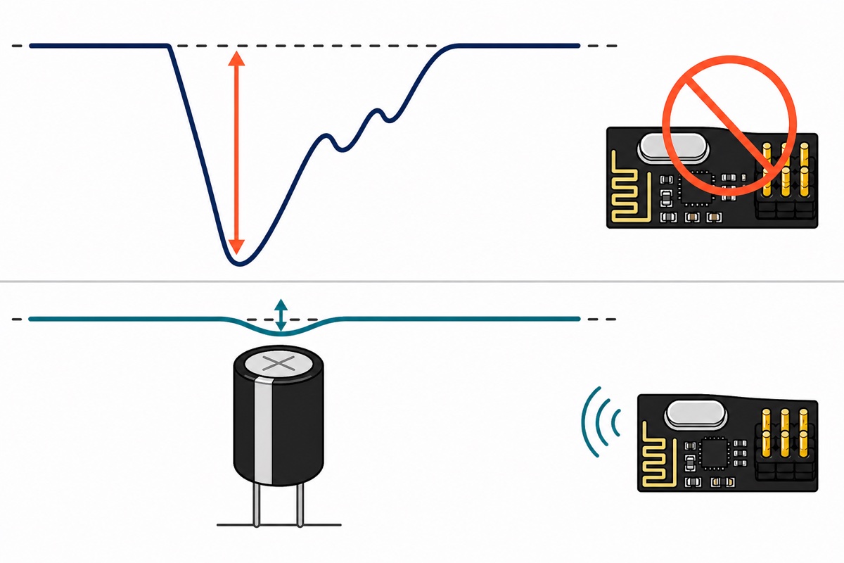
The electrolytic is polarised: the stripe down its can marks the negative leg, and that leg goes to GND. Fitted backwards it heats and fails. Any 10–100 µF part rated 6.3 V or more works; the starter kit carries electrolytics alongside its ceramics.
Mounting it is the step most guides skip, because the module’s pins are already wearing jumper sockets. Best: solder the capacitor’s legs straight onto the VCC and GND pins — our header pin soldering guide covers the technique. Solderless: run the module’s VCC and GND leads into a breadboard and bridge the capacitor across those two rows, a few centimetres from the chip instead of a jumper’s length plus the Uno’s own tracks. Worst: the Uno’s 3V3 and GND holes, which leaves the entire jumper inside the path you were trying to bypass. Both nodes get one, which is why the parts list carries two breadboards.
What do addresses and pipes actually do?
The RF24 library’s openWritingPipe() and openReadingPipe() are not network sockets. A pipe address is five bytes riding inside every packet, and the receiving chip compares them in hardware before it wakes the Arduino at all. Both ends share one address, and two links in the same room stay apart by using different ones. It is a filter, not a password: anyone with a matching address hears you.
Roles come from two calls, not from wiring. stopListening() makes a node the transmitter, startListening() makes it the receiver, and swapping those lines between the sketches changes no hardware.
Acknowledgement is where the mental model usually breaks. When a packet arrives and passes its CRC, the receiver turns its own transmitter on and answers automatically. So both ends transmit, both ends need the capacitor, and write() returning true is a delivery report rather than a “sent” flag. It also explains the pipe numbering: pipe 0 is reserved for those acknowledgements, so a hub uses pipes 1 to 5. Those four share the top four bytes of pipe 1’s address and differ only in the last, because the chip stores one full five-byte address for the group and a single byte per pipe after it.
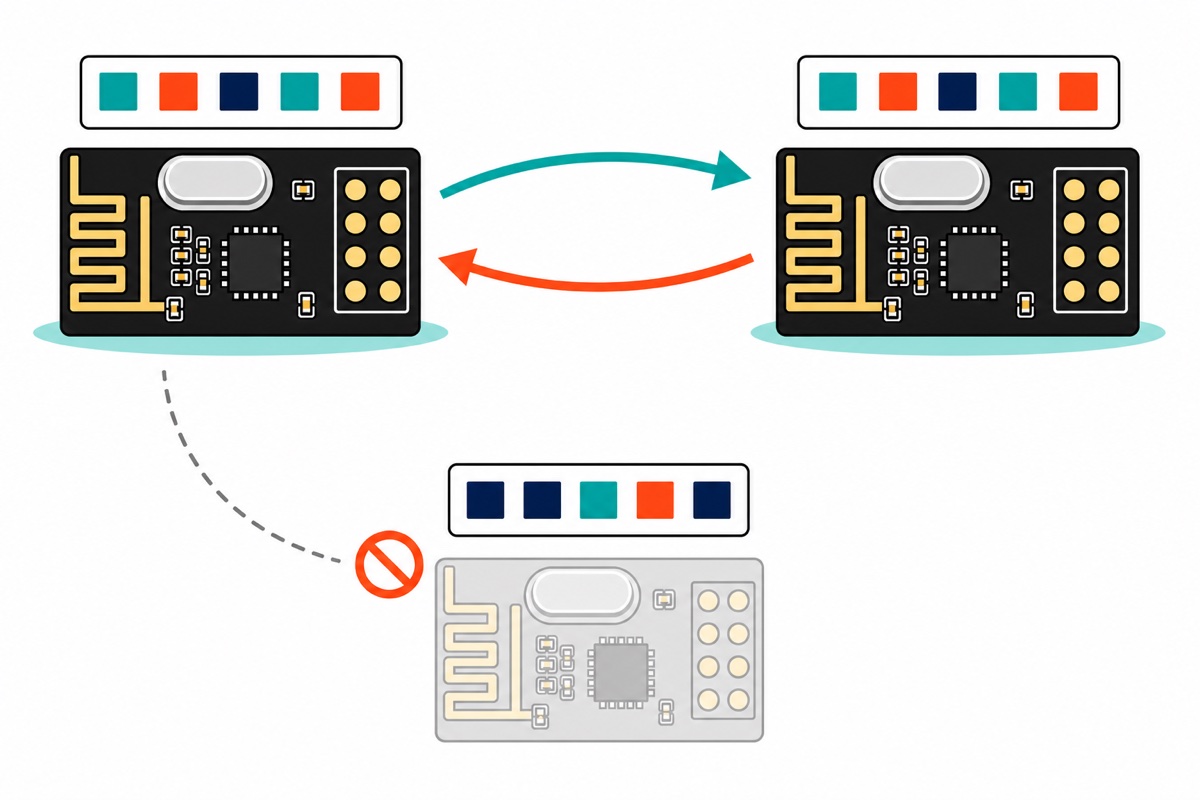
That last detail turns this two-node link into a network of sensors reporting to one board:
What does the nRF24L01 transmitter and receiver code look like?
Both sketches use RF24 by TMRh20 — open Library Manager, search RF24, install. Upload the transmitter to the node with the button and the receiver to the other, then open both Serial Monitors at 115200 — two IDE windows, since one window watches one port. Each node needs its own power the moment they separate: a USB cable, a charger or a power bank each. Nothing else is shared between the two nodes, not even ground.
/*
  nRF24L01 remote button - TRANSMITTER node (Arduino Uno + RF24 by TMRh20).

  nRF24L01 VCC -> Uno 3V3  (NEVER 5V)      GND -> Uno GND
  CE  -> D9      CSN -> D10
  SCK -> D13     MOSI -> D11      MISO -> D12      IRQ -> not used
  10-100uF electrolytic across the module's own VCC and GND pins, stripe to GND.

  Button between D2 and GND. INPUT_PULLUP means no external resistor.
  The node sends one byte on every change and again every 200 ms, so the
  receiver can tell "still pressed" from "link died".
*/

#include <SPI.h>
#include <RF24.h>

RF24 radio(9, 10);                 // CE, CSN

const byte address[6] = "MHUB1";   // 5 bytes; must be identical on both nodes

const uint8_t  PIN_BUTTON   = 2;
const uint16_t DEBOUNCE_MS  = 25;  // contacts settle in a few ms; 25 is safe
const uint16_t HEARTBEAT_MS = 200; // repeat the current state this often

uint8_t  stableState = 0;          // 1 = pressed
uint8_t  lastRaw     = 0;
uint32_t lastEdgeAt  = 0;
uint32_t lastSendAt  = 0;

void setup() {
  Serial.begin(115200);
  pinMode(PIN_BUTTON, INPUT_PULLUP);

  if (!radio.begin()) {
    // begin() reads a register back. Failing here is wiring or supply,
    // never radio range - the other node is not involved yet.
    Serial.println(F("radio not responding: check 3.3V, CE/CSN, capacitor"));
    while (1) {}
  }

  // RF24_PA_LOW is -12 dBm - gentler on a weak 3.3V rail than the 0 dBm
  // RF24_PA_MAX, which is the one to use once the supply is solid.
  radio.setPALevel(RF24_PA_LOW);
  // RF24_250KBPS trades throughput for receiver sensitivity, but that rate
  // exists only on nRF24L01+ silicon; setDataRate() returns false if refused.
  radio.setDataRate(RF24_1MBPS);
  radio.setChannel(76);             // 2476 MHz - above Wi-Fi 1/6/11, in band
  radio.setPayloadSize(sizeof(stableState));
  radio.openWritingPipe(address);
  radio.stopListening();            // this node talks

  Serial.println(F("transmitter ready"));
}

void loop() {
  uint8_t  raw = (digitalRead(PIN_BUTTON) == LOW);  // pulled up: LOW = pressed
  uint32_t now = millis();

  if (raw != lastRaw) {             // any bounce restarts the settling clock
    lastRaw    = raw;
    lastEdgeAt = now;
  }

  bool changed = false;
  if (raw != stableState && (now - lastEdgeAt) >= DEBOUNCE_MS) {
    stableState = raw;
    changed     = true;
  }

  if (changed || (now - lastSendAt) >= HEARTBEAT_MS) {
    lastSendAt = now;

    // write() returns true only when the receiver's auto-ACK came back,
    // so it is a delivery report, not a "sent" flag.
    bool acked = radio.write(&stableState, sizeof(stableState));

    if (changed) {
      Serial.print(stableState ? F("pressed  ") : F("released "));
      Serial.println(acked ? F("- ack received") : F("- NO ack"));
    }
  }
}
/*
  nRF24L01 remote button - RECEIVER node (Arduino Uno + RF24 by TMRh20).

  Wiring is identical to the transmitter:
  VCC -> 3V3, GND -> GND, CE -> D9, CSN -> D10, SCK -> D13, MOSI -> D11,
  MISO -> D12, plus the 10-100uF capacitor across the module's VCC and GND.

  D3 is the output pin. It drives the relay module's IN terminal, or an LED
  with a series resistor. D13 is NOT available as an indicator here: on an
  Uno that pin is SPI SCK and the radio owns it.
*/

#include <SPI.h>
#include <RF24.h>

RF24 radio(9, 10);                 // CE, CSN

const byte address[6] = "MHUB1";   // same five bytes as the transmitter

const uint8_t  PIN_OUT     = 3;
const uint16_t FAILSAFE_MS = 1000; // 5 missed heartbeats = link gone

uint8_t  lastState = 0;
uint32_t lastHeard = 0;

void setup() {
  Serial.begin(115200);
  pinMode(PIN_OUT, OUTPUT);
  digitalWrite(PIN_OUT, LOW);      // drive the output off before anything else

  if (!radio.begin()) {
    Serial.println(F("radio not responding: check 3.3V, CE/CSN, capacitor"));
    while (1) {}
  }

  radio.setPALevel(RF24_PA_LOW);    // every setting below must match the TX
  radio.setDataRate(RF24_1MBPS);
  radio.setChannel(76);
  radio.setPayloadSize(sizeof(lastState));
  radio.openReadingPipe(1, address);  // pipe 1 listens on the shared address
  radio.startListening();             // this node listens

  Serial.println(F("receiver listening"));
}

void loop() {
  if (radio.available()) {
    uint8_t state = 0;
    radio.read(&state, sizeof(state));
    lastHeard = millis();

    if (state != lastState) {
      lastState = state;
      digitalWrite(PIN_OUT, state ? HIGH : LOW);
      Serial.println(state ? F("output ON") : F("output OFF"));
    }
  }

  // Nothing heard for a second: the transmitter is off, out of range or
  // dead. Release the output rather than leave it stuck on.
  if (lastState && (millis() - lastHeard) > FAILSAFE_MS) {
    lastState = 0;
    digitalWrite(PIN_OUT, LOW);
    Serial.println(F("link lost - output released"));
  }
}
On an Uno the transmitter compiles to 3,802 bytes of flash and 244 bytes of RAM; the receiver to 3,424 and 239. The output is D3 and deliberately not D13: on an Uno that pin is SPI clock and the radio owns it, so the onboard LED flickers with traffic and is useless as an indicator. Take D3 to the relay module‘s IN screw terminal, and power the module itself: DC+ to the Uno’s 5 V, DC- to GND. A signal on IN with nothing powering the board switches nothing. Set the H/L trigger jumper to H, because the sketch’s off state is a LOW on D3 — driven at startup, and returned to whenever the failsafe fires — and on the L setting each of those off moments energises the relay instead, so a lost link would switch the load on rather than off. Keep the switched side low-voltage DC; mains brings its own rules on enclosures, clearances and cable rating, so read our relay module safety guide first.
The heartbeat and the failsafe are a pair: the transmitter repeats the button state every 200 ms, and the receiver drops its output after a second of silence, so a flat battery or a walk out of range switches the load off instead of leaving it latched on. Swap the button for a joystick and the same structure carries two axes.
PCB antenna or the antenna version — which one should you buy?
| NRF24RF (PCB antenna) | NRF24AN (antenna version) | |
|---|---|---|
| Antenna | Gold trace etched into the board | SMA socket, duck antenna screws on |
| Transmit | Bare chip, up to 0 dBm | Power amplifier, around +20 dBm |
| Receive | Bare chip | Low-noise amplifier ahead of the chip |
| Peak transmit current | 11.3 mA | Roughly 115 mA |
| Uno 3V3 pin can feed it | Yes, with the capacitor | No — needs its own 3.3 V supply |
| Good for | Same room, next room, across a small house | Across a field, between buildings |
The NRF24AN’s advantage is arithmetic, not marketing. The amplifier adds roughly 20 dB on transmit and the low-noise amplifier about 10 dB on receive, so the link budget improves by around 30 dB. Free-space loss rises 6 dB every time distance doubles, since the same power spreads over four times the area, so 30 dB is five doublings — about thirty times the range, which is how open-field figures in the hundreds of metres sit beside a plain module that manages tens. Those maxima are clear line-of-sight, and walls and bodies each eat several dB of that budget.
Range costs power. At 115 mA the antenna version asks more than twice what the Uno’s 3V3 pin is rated for, so hanging it there makes the brownout worse rather than better: run it at RF24_PA_LOW, fit at least 100 µF, and give it a dedicated 3.3 V supply with its ground tied to the Uno’s. Upgrade both ends, since the acknowledgement means the far node transmits too — then separate them before judging the result, because a low-noise amplifier is built for faint signals and two amplified modules a hand’s width apart swamp each other’s front ends. Give them several metres for the first test. One detail decides whether an antenna works at all — the module’s jack is standard SMA, while most spare Wi-Fi antennas are RP-SMA. Reverse polarity swaps the contacts and not the thread: both halves end up with a socket, so they screw together with nothing but air where the pin should be.
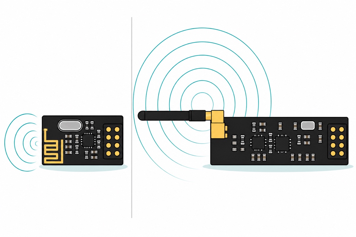
When is the nRF24L01 the wrong radio?
The nRF24L01 is a short-range, high-rate link, and three jobs suit something else. Kilometres for a handful of bytes a minute — a water tank across a plantation, a gate sensor down a long drive — is LoRa territory: a sub-GHz spread-spectrum radio that trades data rate for reach, a different design rather than a bigger nRF24, and not something we carry.
If one end is a phone, you want Bluetooth, not a radio the phone does not have — our HC-05 guide covers that pairing and the Bluetooth RC car is the same idea driving motors. If both ends are already ESP32s, ESP-NOW uses Wi-Fi silicon you have paid for and needs no extra module. The nRF24L01 wins exactly here: two microcontrollers, a room or a house apart, cheap enough to put on both ends.
Common mistakes we see from real customers
5 V on the VCC pin. The logic pins really are 5 V tolerant; the supply pin tops out at 3.6 V. One wrong header hole and the module never answers begin() again.
Skipping the capacitor because it “works on the bench”. A short packet at close range survives a sagging rail; the same link three rooms away does not.
Sketches that disagree. Channel, data rate, address and payload size must match, and startListening() on both ends leaves two receivers and no transmitter. Both failures are silent — no error, just a receiver that never reports anything.
FAQ
Why does radio.write() always return false?
No acknowledgement came back: either the receiver’s settings differ, or the transmitter’s supply is sagging during the burst. Fit the capacitor first, then compare the sketches.
Can I power the nRF24L01 from the Arduino’s 5 V pin?
No. 3.6 V is the absolute maximum on VCC. Use 3V3 — the signal pins are 5 V tolerant, the supply pin is not.
What capacitor value should I use?
10–100 µF electrolytic, 6.3 V or more, across the module’s own VCC and GND pins with the striped leg to GND. Use 100 µF for the antenna version.
Do both modules need to be the same type?
No, they pair fine. But range is set by the weaker end, so upgrading only one buys far less than expected.
How far will two modules reach indoors?
A PCB-antenna pair covers a room comfortably and usually a wall or two beyond. Houses here are brick and reinforced concrete rather than timber and plasterboard, so a wall costs more signal than the same wall in a video filmed elsewhere. If it drops sooner than that, check the supply before blaming range.
Last updated August 2026. Stuck? Chat with us on WhatsApp.
