

Tutorials
Raspberry Pi Pico / RP2040: First Sketch and Pinout in the Arduino IDE
Aug
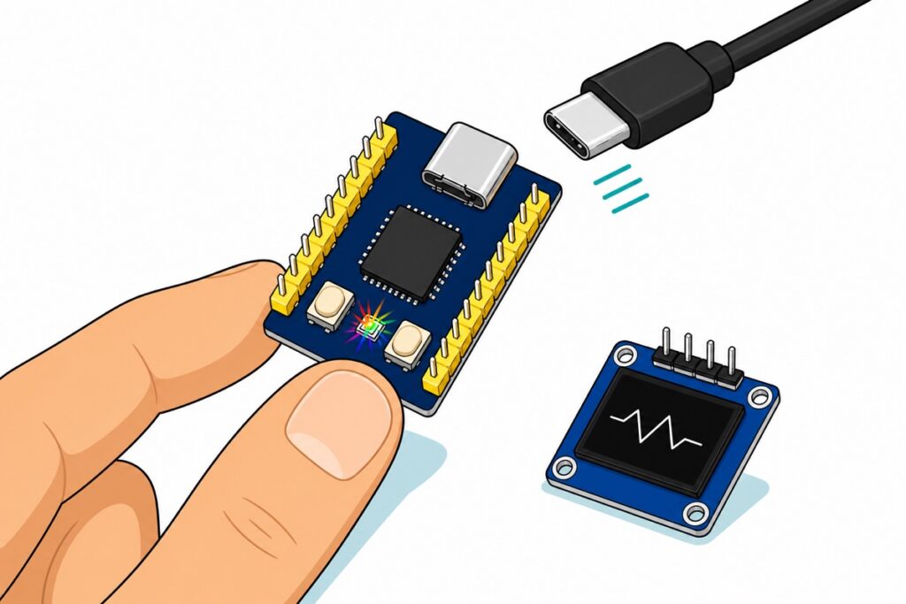
An RP2040 board needs no driver and no COM port for its first flash. Install the free “Raspberry Pi Pico/RP2040/RP2350” core by Earle F. Philhower, III from Boards Manager, hold the board’s BOOT button while plugging in USB, and the board mounts as a flash drive named RPI-RP2 that the Arduino IDE uploads straight into. This guide takes the RP2040-Zero from empty desk to a live OLED readout.
Which RP2040 board should you start with?
The RP2040-Zero is the plug-and-play pick, and the one this guide is built on. It is a stamp-sized navy board that makes the RP2040’s essentials convenient: USB-C on the board itself, BOOT and RESET buttons on the face, and yellow header pins already soldered along both edges. Underneath sits the same dual-core 133 MHz Cortex-M0+, 264 KB of RAM and 2 MB of flash as its bigger siblings.
The classic Raspberry Pi Pico runs the same chip in the canonical 40-pin outline that every pinout diagram is drawn around, and it ships with bare pads — plan a session with our header-soldering guide before it meets a breadboard. The RP2040-Tiny sits at the other extreme: the chip on a castellated solder-in module, with its USB-C port and buttons on a separate adapter board joined by a ribbon cable. Buy it to shrink a finished project — flash through the adapter, then detach the ribbon and solder the module into your build — not for a first sketch.
Parts list — the board, the display, and the cable and jumpers that join them
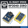 RP2040-Zero Microcontroller Board Raspberry Pi Dual Core ARM Cortex M0+ 133MHz USB Type-C DIY Project
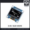 0.96‘ OLED Display Module Blue White Screen I2C IIC Serial 128X64 LCD Display Board - 0.96' OLED WHITE
 Data Cable Type-A Type-C MicroUSB Type-B 0.5m 1m 30cm 0.3m 100cm Data Transfer Upload Code - TYPE-A TO TYPE-C CABLE (1.0M)
 40pcs Dupont Wire 10cm 20cm 30cm for Breadboard DIY Experiment Jumper Wire Breadboard wire - DUPONT WIRE F-F 20CM
Parts list
 MB102 Breadboard 170 400 830 Holes Breadboard Donut Board Arduino Prototype Multi Color - BREADBOARD (400 HOLES)
 40pcs Dupont Wire 10cm 20cm 30cm for Breadboard DIY Experiment Jumper Wire Breadboard wire - DUPONT WIRE M-M 20CM
Prefer a breadboard base for expanding later? The Zero's soldered pins plug straight into a 400-hole breadboard, and male-to-male jumpers then run the same four OLED connections.
How do you set up the Arduino IDE for the RP2040?
The Arduino IDE does not know the RP2040 until a board package teaches it. In File → Preferences, paste this into Additional boards manager URLs:
https://github.com/earlephilhower/arduino-pico/releases/download/global/package_rp2040_index.json
Then open Boards Manager, search “pico”, install Raspberry Pi Pico/RP2040/RP2350 by Earle F. Philhower, III, and pick Waveshare RP2040 Zero under Tools → Board. That exact choice matters more than it looks — the next section shows why.
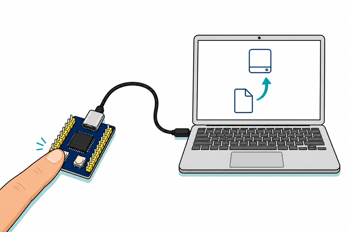
Now the part that surprises anyone coming from ESP32: there is no driver step. An ESP32 board talks USB through a separate bridge chip, and until its vendor driver is installed nothing appears — the whole saga our “board not detected” guide exists to fix. The RP2040 speaks USB itself, from a bootloader etched into the chip’s ROM at the factory. Hold BOOT while power arrives and that ROM enumerates the chip as an ordinary USB mass-storage device — the same class as a thumb drive, so the driver already ships with every operating system. A drive named RPI-RP2 appears, and any UF2 file dropped onto it gets written to flash. Because the ROM can never be overwritten, no failed upload can brick the board: BOOT-and-replug always comes back.
You only need that button dance once. Press Upload and the IDE writes the UF2 to the drive itself; from then on every sketch carries a USB serial port the IDE uses to reboot the board into the bootloader automatically. The Zero’s RESET button saves the replug even in recovery: hold BOOT, tap RESET, release BOOT, and RPI-RP2 is back. One warning about the lead itself: charge-only USB cables have no data wires, so the drive can never appear — the cable in the parts list is a data cable.
Why does the Blink example fail on the RP2040-Zero?
Compile the classic Blink sketch for the RP2040-Zero and the IDE stops with error: 'LED_BUILTIN' was not declared in this scope. That error is the board package doing its job. Every board in the core carries a small pin-definition file naming what the hardware really has, and the Zero’s file deliberately defines no LED_BUILTIN — because there is no plain LED anywhere on the board. Select plain “Raspberry Pi Pico” instead and Blink compiles and uploads happily, and nothing blinks: that file points LED_BUILTIN at GP25, where the official Pico’s green LED lives, and on a Zero GP25 ends at a bare castellated pad with no LED attached. A compile error you can read beats a silent nothing you have to debug.
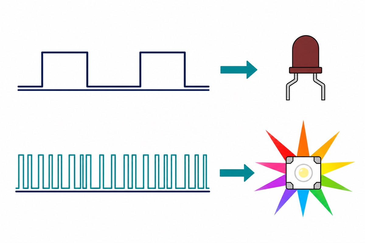
The Zero’s onboard light is better than a plain LED once you know what it is: a WS2812 addressable RGB pixel on GP16. It contains its own tiny controller, and that controller expects 24 bits of colour delivered as a train of precisely-timed pulses at 800 kHz — a steady HIGH from digitalWrite() means nothing to it. Install the Adafruit NeoPixel library from Library Manager and the real first blink is this:
// First blink on the RP2040-Zero. The onboard "LED" is a WS2812 RGB pixel
// on GP16, so it is driven with DATA, not with a HIGH/LOW level.
#include <Adafruit_NeoPixel.h>

// PIN_NEOPIXEL comes from the board's own pin file and equals 16 here.
Adafruit_NeoPixel led(1, PIN_NEOPIXEL, NEO_GRB + NEO_KHZ800);

void setup() {
  led.begin();
  led.setBrightness(40);   // full brightness at desk distance is uncomfortable
}

void loop() {
  led.setPixelColor(0, led.Color(0, 150, 0));   // green
  led.show();
  delay(500);
  led.setPixelColor(0, 0);                      // off
  led.show();
  delay(500);
}
It compiles to 56,764 bytes — under 3% of the Zero’s flash. Our WS2812 guide takes the same pixel onward to strips and rings.
How do you read an RP2040 pinout?
On every RP2040 board, a pin’s identity is its GP number, not its physical position. The chip has 30 GPIO, GP0 to GP29, and each board simply chooses which of them to bring to its edges — so code written against GP numbers moves between a Pico and a Zero unchanged, and any pinout diagram works once you match labels instead of counting corners. The Zero’s headers carry GP0–GP15 plus the four analog-capable pins; GP16 is spent internally on its WS2812, and nine more GPIO surface only as solder pads on the board’s bottom edge:
| Label on the Zero | What it is |
|---|---|
| 5V | Power straight from the USB lead — an output for feeding 5 V parts, never a signal pin |
| 3V3 | The onboard regulator’s 3.3 V output — the rail the chip itself runs on |
| GND | Common ground for everything on the desk |
| GP0–GP15 | Digital I/O; UART, SPI, I2C and PWM can each be mapped onto them |
| GP26–GP29 | Digital I/O that double as analog inputs ADC0–ADC3 |
| GP16 | Not on the headers — it drives the onboard WS2812 pixel |
| GP17–GP25 | Not on the headers either — bare solder pads on the bottom edge, for solder-in builds rather than jumpers |
One rule keeps the board alive: the RP2040’s I/O runs from the 3.3 V rail, and its pins are not 5 V-tolerant — the 5V pin exists to power 5 V devices, never to meet a GP pin.
How do you wire the OLED — and put the pinout to work?
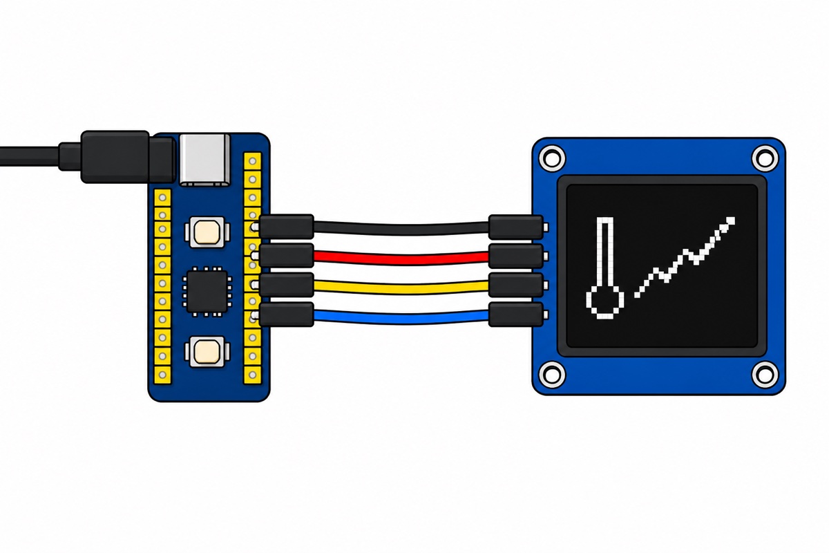
The payoff build is a live readout, and it needs no breadboard and no soldering: the Zero’s soldered headers are male pins, the 0.96-inch OLED‘s pre-fitted 4-pin header is male too, so four female-to-female jumpers bridge them directly. One habit to break first: this OLED’s header reads GND VCC SCL SDA — ground first, the reverse of many hobby modules. Match the silkscreen, not muscle memory, before power goes on.
| OLED pin | RP2040-Zero pin | Why |
|---|---|---|
| GND | GND | Shared reference for the bus |
| VCC | 3V3 | The SSD1306 runs happily from 3.3 V, and its bus levels then match the chip’s |
| SCL | GP5 | GP5 sits in the chip’s I2C0 clock group |
| SDA | GP4 | GP4 sits in the chip’s I2C0 data group |
GP4 and GP5 are not arbitrary. The RP2040 lets each interface appear on several pins, in a fixed pattern: starting from GP0, every fourth pin can be I2C0’s SDA, and every fourth starting from GP1 its SCL. The sketch states the choice out loud with Wire.setSDA(4) and Wire.setSCL(5) — one line each, and the wiring is documented in the code instead of in your memory. This display is driven by an SSD1306 controller answering at I2C address 0x3C, and for a first readout the chip brings its own data: the RP2040 has an on-die temperature sensor, read with one call. Install Adafruit SSD1306 from Library Manager first, letting the IDE pull in its Adafruit GFX dependency when it asks.
// RP2040-Zero + 0.96in SSD1306 OLED over I2C0: live chip-temperature readout.
// Wiring: OLED GND -> Zero GND, VCC -> 3V3, SCL -> GP5, SDA -> GP4.
#include <Wire.h>
#include <Adafruit_GFX.h>
#include <Adafruit_SSD1306.h>

Adafruit_SSD1306 oled(128, 64, &Wire, -1);

void setup() {
  // Say the pins out loud rather than trusting a default: GP4 sits in the
  // chip's I2C0-SDA group and GP5 in its I2C0-SCL group.
  Wire.setSDA(4);
  Wire.setSCL(5);

  oled.begin(SSD1306_SWITCHCAPVCC, 0x3C);   // this module answers at 0x3C
  oled.setTextColor(SSD1306_WHITE);
}

void loop() {
  float t = analogReadTemp();   // RP2040's own on-chip sensor, in Celsius

  oled.clearDisplay();
  oled.setTextSize(1);
  oled.setCursor(0, 0);
  oled.print("RP2040 core temp");
  oled.setTextSize(3);
  oled.setCursor(0, 24);
  oled.print(t, 1);
  oled.setTextSize(2);
  oled.print(" C");
  oled.display();

  delay(1000);
}
That one compiles to 71,100 bytes, and the number it shows is derived, not magic: the sensor puts out 0.706 V at 27 °C and drops 1.721 mV per degree, so the core computes 27 − (V − 0.706) / 0.001721 — the formula straight from the RP2040 datasheet. Expect a reading a few degrees above the room: it is the die’s own temperature, and pressing a fingertip on the chip moves it. When the screen wants a real interface, our rotary encoder menu guide is the natural next step — same display, same I2C bus.
Common mistakes we see from real customers
The cable charges but never mounts the drive. Charge-only USB leads have no data wires, so RPI-RP2 cannot appear and the board reads as dead. Swap to a known data cable before suspecting the hardware.
Hunting for a COM port while the board is in BOOTSEL mode. In bootloader mode the board is a flash drive, not a serial device — no port is the correct behaviour. The port appears after a sketch is running.
Blink “works” but nothing happens. Board menu set to plain Raspberry Pi Pico drives GP25, which on a Zero is only a bare solder pad with no LED. Select Waveshare RP2040 Zero and drive the WS2812 on GP16 with a NeoPixel-type library instead.
The OLED is wired VCC-first by habit. This module’s header runs GND VCC SCL SDA, so habit-wiring reverses the supply across the display. Read the silkscreen on the module every time, before power.
A 5 V sensor output goes straight into a GP pin. The RP2040’s pins are 3.3 V-only. Power 5 V parts from the 5V pin by all means, but divide their signal lines down before they reach the chip.
FAQ
Should I start with the Raspberry Pi Pico or the RP2040-Zero?
Same chip, same code, different packaging. The Zero arrives with headers soldered and USB-C, so it is the faster start; the Pico gives you the canonical 40-pin outline that matches every diagram online, with pads you solder yourself.
Do I need to solder anything for this build?
No. The Zero’s pins and the OLED’s 4-pin header both come pre-soldered, and the four female-to-female jumpers connect pin to pin directly. Soldering only enters the picture if you choose the Pico or the RP2040-Tiny lane.
Can the RP2040 run MicroPython instead?
Yes — the same RPI-RP2 drive accepts a MicroPython firmware UF2, after which the board talks to Thonny instead of the Arduino IDE. This guide stays with Arduino so your Uno and ESP32 sketch experience carries over directly.
Are the RP2040’s pins 5V tolerant?
No. All GPIO run at 3.3 V logic, and 5 V on a pin risks the chip. The Zero’s 5V pin is a power output from USB for feeding 5 V devices — their signal lines still need dividing down to 3.3 V.
Why is there no COM port when I first plug the board in?
A COM port is created by a running sketch, not by the chip, so an empty port list on a fresh board is normal rather than a fault. Hold BOOT while plugging in and the board mounts as the RPI-RP2 flash drive instead; upload any sketch and the core adds a USB serial port that the IDE lists like any other Arduino.
The habit this page builds is the platform itself: match GP numbers instead of positions, check what a board’s pin file really defines, and every RP2040 board — Zero, Pico or a castellated module in a finished product — becomes the same machine.
Last updated August 2026. Stuck? Chat with us on WhatsApp.
