

Tutorials
Rotary Encoder Arduino: Build a Scrollable OLED Menu
Aug
Put the KY-040’s CLK pin on D2, count detents inside an interrupt, and call display() only when the count has actually changed. That last rule is the whole article: a full 128×64 OLED redraw blocks an Arduino Uno for roughly 25 ms, and a quick flick of the knob buries several detents inside that gap.
Why does a rotary encoder need two output pins instead of one?
The KY-040 has two switching contacts inside that silver can, wired out as CLK and DT, deliberately offset so one changes state a quarter of a cycle before the other. An edge on CLK alone is useless — the contact opens identically whether you turn the shaft clockwise or anticlockwise. Direction does not live in either signal. It lives in the phase between them.
So read the other channel at the instant the first one moves: sample DT as CLK falls, and it is still HIGH one way, already LOW the other. One digitalRead — that is why the module has two signal pins.
| Within one detent | Turning clockwise | Turning anticlockwise |
|---|---|---|
| At rest in a detent | CLK HIGH, DT HIGH | CLK HIGH, DT HIGH |
| 1st transition | CLK falls — DT still HIGH | DT falls — CLK still HIGH |
| 2nd transition | DT falls — both LOW | CLK falls — DT already LOW |
| 3rd transition | CLK rises — DT still LOW | DT rises — CLK still LOW |
| 4th transition | DT rises — back at rest | CLK rises — back at rest |
The two bold rows are the whole decoder. Read the table downwards instead and you get the other half: one click is four electrical transitions, not one — the cause of the most common complaint about this module. This walkthrough works through the same two-pulse principle and puts a quadrature pair on an oscilloscope as real square waves:
Parts list — the knob, the screen, and the wiring that actually reaches them
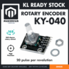 Rotary Encoder KY-040 360 Degree Encoder Sensor Module High Precision Knob
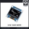 0.96‘ OLED Display Module Blue White Screen I2C IIC Serial 128X64 LCD Display Board - 0.96' OLED WHITE
 Arduino Uno Compatible SMD UNO R3 with Type B Cable - ATMEGA328P with CH340G-Microcontroller Project
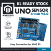 Sensor Shield V5.0 Arduino Uno R3 Shield For Arduino Protoype Application
 40pcs Dupont Wire 10cm 20cm 30cm for Breadboard DIY Experiment Jumper Wire Breadboard wire - DUPONT WIRE F-F 20CM
Parts list
| Item | Price | Qty | |
|---|---|---|---|
 Power Supply Adapter DC Universal AC to DC Converter PSU 5V2A 5V3A 9V2A 12V2A - P.S. ADAPTOR (9V2A)PSA0902 Power Supply Adapter DC Universal AC to DC Converter PSU 5V2A 5V3A 9V2A 12V2A - P.S. ADAPTOR (9V2A)PSA0902 | RM13.95 |
A 9V 2A centre-positive adaptor, if you want the finished menu to run without a PC plugged into it. 9V sits comfortably inside the Uno R3's 7–12V barrel-jack window; 12V also works, but the Uno's regulator is linear, so every extra volt is burned off as heat for no benefit.
How do you connect a KY-040 and an OLED to an Uno?
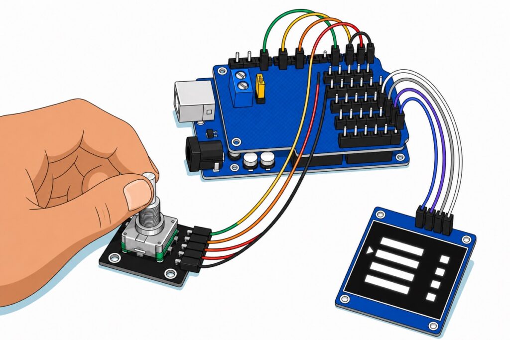
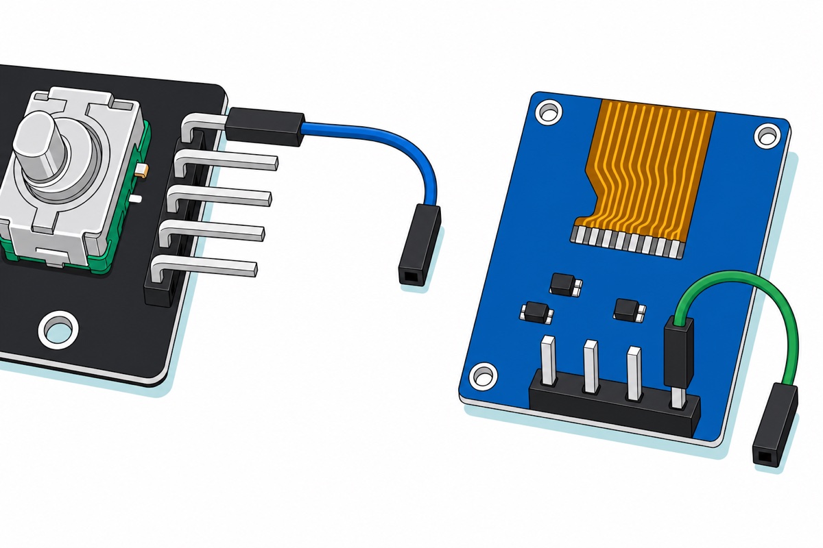
The KY-040 and the 0.96″ OLED both present male pins, and the Uno‘s headers are female sockets, so they cannot mate directly. The Sensor Shield V5.0 fixes that: it presses onto the Uno and republishes every pin as a three-pin male block silkscreened G, V and S — ground, five volts, signal. Nine female-to-female jumpers then reach both modules, with no soldering anywhere.
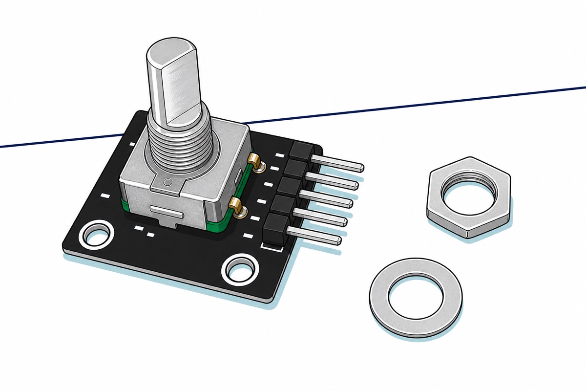
A breadboard, the usual alternative, does not work here. On the KY-040’s five-pin header the black body stands on the right edge and the silver pins bend ninety degrees and run out sideways, parallel to the PCB — nothing points downwards, so nothing can be pushed into breadboard holes. Female sockets on those horizontal pins are the only option.
The OLED needs no preparation either: its four-pin male header arrives already soldered to the back face. What looks like four bare holes on the front is the solder fillets and pin ends seen end-on. Plug a female jumper on and you are wiring, not soldering.
Check two things before the first jumper goes on. First, the OLED’s pins run GND, VCC, SCL, SDA — ground first, the reverse of the usual VCC-first order — while the shield’s IIC header runs SCL, SDA, −, +. The two are mirrored, so a straight-across ribbon gets all four wrong. Land one wire at a time: GND and VCC swapped puts the supply across the panel backwards and can kill it.
Second, the shield’s yellow SEL jumper, beside the blue screw terminal. It arrives fitted, which is what this build wants: it feeds the V pins of the D0–D13 blocks from the Uno’s own 5V. Pull it and those V pins stay dead until you feed the screw terminal yourself. The A0–A5 blocks and the IIC header take Uno 5V either way, so a missing SEL gives a convincing fault: the menu draws perfectly and the knob does nothing, because the screen had power and the encoder never did. And never feed the screw terminal while SEL is fitted: that ties an outside supply straight onto the Uno’s 5V rail.
| Module pin | Where it goes on the shield | Uno pin behind it |
|---|---|---|
| KY-040 CLK | D2 block, S pin | D2 (INT0) |
| KY-040 DT | D3 block, S pin | D3 (INT1) |
| KY-040 SW | D4 block, S pin | D4 |
| KY-040 + | any block’s V pin | 5V |
| KY-040 GND | any block’s G pin | GND |
| OLED GND | IIC header, − | GND |
| OLED VCC | IIC header, + | 5V |
| OLED SCL | IIC header, SCL | A5 |
| OLED SDA | IIC header, SDA | A4 |
On the Uno, A4 and A5 are the I2C bus; the shield’s IIC header is just a tidier place to land them.
The encoder’s shaft is a bare 6 mm D-flat, so any 6 mm D-shaft knob presses straight on.
Why does the menu jump two or four items per click?
A KY-040 detent is not a pulse. The knob turns through 20 detents per revolution, and one detent spans one complete quadrature cycle — the four transitions in the table above. These encoders are ordered by that pairing: Bourns’ PEC11R datasheet lists detent options “1 = 18 Detents (18 pulses)” and “2 = 24 Detents (12, 24 pulses)” — one whole quadrature cycle per detent, or two detents to a cycle on the halved variants. A “pulse per 360° rotation” is counted on one channel, so the KY-040’s 20 detents give 20 pulses on CLK and 20 on DT.
Count every edge on both channels and you get four per click; both edges of one channel, two. Count CLK’s falling edge alone, as the sketch below does, and you get exactly one. The encoder was never faulty; the counting model was.
The other thing that inflates the count is contact bounce. These are mechanical wipers, and the same Bourns datasheet specifies bounce at 2.0 ms maximum, so one detent can throw several extra edges at the pin. The cure is a micros() timestamp inside the interrupt handler that refuses any edge arriving less than 2 ms after the last accepted one. It must be micros(): millis() is advanced by its own timer interrupt, which cannot run while your handler holds the CPU. Never delay() in there either — interrupts are off, so it stalls the I2C transfer and the next edge with it.
Declare CLK, DT and SW as INPUT_PULLUP. The KY-040’s contacts switch to ground, so without a pull-up an open contact leaves the pin floating and reading noise. The ATmega328P datasheet puts its internal pull-up at 20–50 kΩ; on revisions that also carry their own 10 kΩ pull-ups the two sit in parallel and still hold the pin solidly HIGH, and on revisions without them the internal pull-up is the only thing doing the job. Correct either way.
Why does redrawing the screen make the knob miss steps?
Adafruit_SSD1306 keeps the entire screen in RAM and ships it in one go. It allocates WIDTH × ((HEIGHT + 7) / 8) bytes — for a 128×64 panel, 128 × 8 = 1024 bytes — and display() pushes all of them over I2C. The library raises the bus to 400 kHz for its own transfers, and every byte on I2C costs nine bit periods: eight data bits plus the acknowledge the display sends back. So 1024 × 9 = 9216 bit periods, and at 400 kHz that is 23 ms. Add the restart and address byte the library spends on each 32-byte chunk and a full redraw blocks the Uno for roughly 25 ms. During it, loop() is not running. Only an interrupt can get in.
Measure it on your own board:
unsigned long t = micros();
display.display();
Serial.println(micros() - t);   // microseconds for one full redraw
That buffer costs memory as well as time, and it hides: 1024 bytes is exactly half of the ATmega328P’s 2 KB of SRAM, but it is allocated at run time inside display.begin(), so it never appears in the figure the IDE prints after compiling. The sketch below reports 543 bytes of globals — until begin() claims 1024 more and the true figure is about 1567 of 2048. Hence the menu labels living in flash behind PROGMEM and strcpy_P: on this chip you cannot spend RAM on four words just to print them.
Which is why the counting moves into an interrupt. D2 and D3 are the Uno’s only external-interrupt pins (INT0 and INT1), so putting CLK on D2 is not arbitrary — it is why the pin table looks the way it does. An ISR on D2 fires during the transfer, so a detent landing in the blind spot is still recorded. loop() then compares the count against what is on screen and redraws only when they differ: spin the knob ten detents quickly and you get far fewer than ten redraws, but you land on the right item.
What does the menu sketch actually look like?
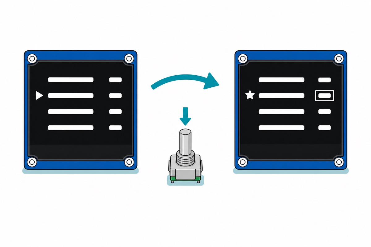
A menu is a small state machine with three pieces of state: menuIndex for the row the marker is on, a bool editing for what the knob is attached to, and a values[] array for the numbers. The knob moves menuIndex while browsing and values[menuIndex] while editing; the push switch toggles between the two. The pattern transplants onto anything with settings — the DS3231 clock this menu was born to set, or the keypad lock‘s timeouts.
// Rotary encoder + OLED scrollable menu, Arduino Uno.
// Wiring: KY-040 CLK -> D2 (INT0), DT -> D3, SW -> D4, + -> 5V, GND -> GND.
//         OLED SCL -> A5, SDA -> A4, VCC -> 5V, GND -> GND.
// The whole point: count in the interrupt, redraw only when the count changed.

#include <Wire.h>
#include <Adafruit_GFX.h>
#include <Adafruit_SSD1306.h>

#define SCREEN_WIDTH 128
#define SCREEN_HEIGHT 64
#define OLED_RESET -1
#define OLED_ADDR 0x3C   // silkscreen says 0x78; that is the 8-bit form, 0x78 >> 1 = 0x3C

Adafruit_SSD1306 display(SCREEN_WIDTH, SCREEN_HEIGHT, &Wire, OLED_RESET);

const uint8_t PIN_CLK = 2;   // INT0 - one of only two external-interrupt pins on an Uno
const uint8_t PIN_DT  = 3;
const uint8_t PIN_SW  = 4;

const uint8_t ITEMS = 4;

// Labels live in flash, not in SRAM - the frame buffer already owns half the RAM.
const char item0[] PROGMEM = "Hour";
const char item1[] PROGMEM = "Minute";
const char item2[] PROGMEM = "Brightness";
const char item3[] PROGMEM = "Beep";
const char *const MENU[ITEMS] PROGMEM = {item0, item1, item2, item3};
const int8_t VAL_MIN[ITEMS] PROGMEM = {0, 0, 0, 0};
const int8_t VAL_MAX[ITEMS] PROGMEM = {23, 59, 15, 1};

int8_t values[ITEMS] = {7, 30, 8, 1};
uint8_t menuIndex = 0;
bool editing = false;

volatile int8_t encDelta = 0;        // detents seen since loop() last looked
volatile uint32_t lastEdgeUs = 0;

// Runs on every falling edge of CLK. One detent = one full quadrature cycle,
// and a cycle has exactly one CLK falling edge, so this fires once per click.
void onClkFalling() {
  uint32_t now = micros();
  if (now - lastEdgeUs < 2000UL) return;   // contact bounce: ignore 2 ms of chatter
  lastEdgeUs = now;
  if (digitalRead(PIN_DT)) encDelta++;     // DT still HIGH as CLK fell
  else                     encDelta--;     // DT had already gone LOW
}

// Fires once on the press, never on the release, and never on a bounce.
bool buttonPressed() {
  static bool wasDown = false;
  static uint32_t lastChangeMs = 0;
  bool down = (digitalRead(PIN_SW) == LOW);   // INPUT_PULLUP: pressed reads LOW
  if (down != wasDown && millis() - lastChangeMs > 25UL) {
    lastChangeMs = millis();
    wasDown = down;
    return down;
  }
  return false;
}

// The expensive call. Everything above exists so this runs as rarely as possible.
void drawMenu() {
  char label[16];   // must hold the longest label plus its terminator
  display.clearDisplay();
  display.setTextSize(1);
  for (uint8_t i = 0; i < ITEMS; i++) {
    uint8_t y = 4 + i * 15;
    strcpy_P(label, (char *)pgm_read_ptr(&MENU[i]));
    display.setCursor(0, y);
    if (i != menuIndex)  display.print(F("  "));   // not selected
    else if (editing)    display.print(F("* "));   // knob edits this value
    else                 display.print(F("> "));   // knob moves the cursor
    display.print(label);
    display.setCursor(98, y);
    display.print(values[i]);
  }
  display.display();   // ~25 ms of blocked CPU - the reason the ISR exists
}

void setup() {
  pinMode(PIN_CLK, INPUT_PULLUP);
  pinMode(PIN_DT, INPUT_PULLUP);
  pinMode(PIN_SW, INPUT_PULLUP);

  Serial.begin(9600);
  if (!display.begin(SSD1306_SWITCHCAPVCC, OLED_ADDR)) {
    Serial.println(F("No SSD1306 at 0x3C - check SDA/SCL and 5V"));
    for (;;) { }
  }
  display.setTextColor(SSD1306_WHITE);

  attachInterrupt(digitalPinToInterrupt(PIN_CLK), onClkFalling, FALLING);
  drawMenu();
}

void loop() {
  bool changed = false;

  // encDelta is one byte, but clearing it is a read-modify-write, so guard it.
  noInterrupts();
  int8_t steps = encDelta;
  encDelta = 0;
  interrupts();

  if (steps != 0) {
    if (editing) {
      int8_t lo = (int8_t)pgm_read_byte(&VAL_MIN[menuIndex]);
      int8_t hi = (int8_t)pgm_read_byte(&VAL_MAX[menuIndex]);
      int16_t v = (int16_t)values[menuIndex] + steps;
      if (v < lo) v = lo;                 // clamp, do not wrap a value
      if (v > hi) v = hi;
      values[menuIndex] = (int8_t)v;
    } else {
      int16_t i = (int16_t)menuIndex + steps;
      while (i < 0) i += ITEMS;           // wrap the cursor both ways
      menuIndex = (uint8_t)(i % ITEMS);
    }
    changed = true;
  }

  if (buttonPressed()) {
    editing = !editing;
    changed = true;
  }

  if (changed) drawMenu();   // and only then
}
Install Adafruit SSD1306 and Adafruit GFX Library from the Library Manager; the sketch compiles to 15,342 bytes of flash. There is deliberately no encoder library — the handler above is nine lines. Note the noInterrupts() guard in loop(): reading one byte is atomic on an AVR, but reading it and then zeroing it is two operations, and a detent arriving between them would be silently thrown away.
One limit before you reuse this: four rows at a 15-pixel pitch is exactly what a 64-pixel panel holds, so nothing here scrolls yet — a fifth item lands at y = 64, off the bottom of the glass. Past four, draw a window: keep a topIndex, draw four rows from it, and move it only when menuIndex walks off an end.
Common mistakes we see from real customers
The menu advances two or four items per click. Almost always a counting model reacting to every edge, or to both edges of one channel. Count CLK’s falling edge only.
The button reads as permanently pressed. The KY-040’s switch shorts SW to ground and does nothing otherwise, so a plain INPUT leaves the pin floating and the sketch sees phantom presses. Use INPUT_PULLUP and treat LOW as pressed.
The knob “misses steps” only while the screen updates. The tell: slow turns are perfect, fast ones are not. Nothing is wrong with the encoder — the 25 ms redraw is blocking the polling loop. Move the counting into the interrupt.
A blank screen. Open Serial Monitor at 9600 first — the sketch says so if the display never answered, then stops, which is why the board looks dead too. Usually SCL and SDA are swapped on the shield’s IIC header, or 0x78 is in the sketch instead of 0x3C — our OLED monitor guide covers the display side.
FAQ
Which Arduino pins should a KY-040 rotary encoder use?
CLK on D2, DT on D3, SW on D4, + on 5V and GND on GND. D2 and D3 are the Uno’s only external-interrupt pins, so CLK belongs on one of them if counting is to survive a screen redraw.
Why does my rotary encoder skip two or four menu items per click?
One detent is one full quadrature cycle, which is four electrical transitions across CLK and DT. Reacting to all four gives four counts per click; both edges of one channel gives two. React only to CLK’s falling edge and you get exactly one.
Do I need a library for the KY-040?
No. Two INPUT_PULLUP pins, one attachInterrupt on the falling edge of CLK, and one digitalRead of DT inside the handler is the complete decoder. You do need Adafruit SSD1306 and Adafruit GFX for the display.
Is the 0.96″ OLED’s I2C address 0x78 or 0x3C?
Both, in different notations. The board’s silkscreen prints 0x78, the 8-bit form that includes the read/write bit; Arduino’s Wire library wants the 7-bit form, so shift it right by one: 0x78 >> 1 = 0x3C. The alternate jumper position is 0x7A, or 0x3D in the sketch.
Can I run the finished menu without a computer?
Yes — a 9V centre-positive adaptor into the Uno’s barrel jack. The Uno R3 accepts 7–12V there, and the encoder and OLED draw only tens of milliamps from the board’s own 5V rail.
Last updated August 2026. Stuck? Chat with us on WhatsApp.
