

Tutorials
Voice Control an Arduino Relay with the ZK-VR01
Aug
Say a word, and a relay switches. The ZK-VR01 reports every recognition twice over — as bytes on its serial pad T, and as a level change on one of the eight command pads down its left edge — so an Uno only has to watch one lane, latch what it sees, and drive a relay module. Which pad carries which command is a property of your board, so the sketch below reads it first.
What is actually on a ZK-VR01 board?
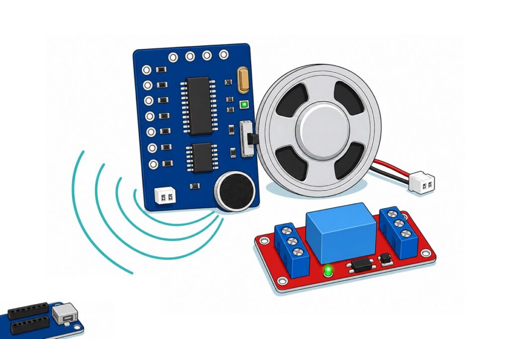
The ZK-VR01 keeps everything you connect to on two edges of one deep-blue board. The top edge carries four holes silkscreened GND, T, R and 5V — power plus a TTL-level serial pair: T is the module’s transmit, R its receive. The left edge carries eight command pads, silkscreened A25, A26, A27, B2, B3, B1, B0 and B7, each with its own series resistor.
Both rows arrive as bare plated through-holes, so nothing plugs in until a 2.54 mm header strip is soldered on. Everything else is fitted: the black-faced electret microphone in its silver rim, the silver OFF/ON slide switch on the right edge, and a white SPK socket for the speaker in the bag, so the board has an audio output as well as a microphone.
Parts list — the voice module, the relay module, and the headers and jumpers that join them
 ZK-VR01 Voice Recognition Module – Voice Commands for Smart Home and DIY Projects
 Relay Module 3.3V 5V 12V 1/2/4/8 Ways Optocoupler Trigger Relay Module 1 2 4 8 Channel Relay Module - 5V RELAY MODULE(1WAY)
 Arduino Uno Compatible SMD UNO R3 with Type B Cable - ATMEGA328P with CH340G-Microcontroller Project
 2.54mm Pin Header Female Male Single Row Header 40P Connector Black White Red Yellow Green Blue - 40P MALE HEADER (BLACK)
 40pcs Dupont Wire 10cm 20cm 30cm for Breadboard DIY Experiment Jumper Wire Breadboard wire - DUPONT WIRE M-F 20CM
 40pcs Dupont Wire 10cm 20cm 30cm for Breadboard DIY Experiment Jumper Wire Breadboard wire - DUPONT WIRE M-M 20CM
Parts list
| Item | Price | Qty | |
|---|---|---|---|
 Soldering Service for Circuit Boards & Electronics - 10 Pins Soldering ServiceSOLSE10 Soldering Service for Circuit Boards & Electronics - 10 Pins Soldering ServiceSOLSE10 | RM1.40 |
The ZK-VR01 arrives with bare pads: four across the top plus one per command you use, so around seven. Add the 10-pin soldering service and we fit the header strip for you.
Why does this build use a relay module rather than a bare relay?
The relay is the same part either way. The sky-blue cube on the 1-way relay module is silkscreened SRD-05VDC-SL-C — the same Songle relay we sell bare as SRD5VRL. The red module adds what belongs between that relay and a microcontroller pin.
Start with the coil. The Songle SRD datasheet gives the 5 V coil 70 Ω and about 0.36 W, so energising it draws 5 V / 70 Ω ≈ 71 mA. The ATmega328P datasheet specifies an I/O pin’s output voltage only up to 20 mA and puts 40 mA as an absolute maximum. 71 mA is not a pin misbehaving; it is a pin worked past its rating. On the finished build that current comes out of the Uno’s 5 V rail through the module’s transistor — a rail can supply it, a pin cannot. Work on USB: the barrel jack reaches the same rail through a linear regulator that turns (Vin − 5 V) × current into heat.
Switching it off is the second problem. An inductor opposes any change in the current through it, so cutting the coil’s supply makes the collapsing field drive whatever voltage it takes to keep that current running — backwards, into whatever did the switching. A diode across the coil offers it a harmless loop instead. A bare relay has none; the module has one, plus a driver transistor and a PC817-type optocoupler between your pin and that driver. Read it as buffering rather than galvanic isolation: the board has one pair of power terminals, so fed from the Uno both sides share its ground and the coil takes the Uno’s supply. What the coupler buys you is that your pin drives only its LED, a few milliamps, instead of the coil. The real separation on this board is the relay’s own contact-to-coil air gap.
Buy SRD5VRL when you are building that driver yourself on perfboard, or replacing a failed relay. Its five pins sit on the Songle footprint, not a 0.1 in grid, so it will not fit a breadboard either.
How do you wire the ZK-VR01, the Uno and the relay?
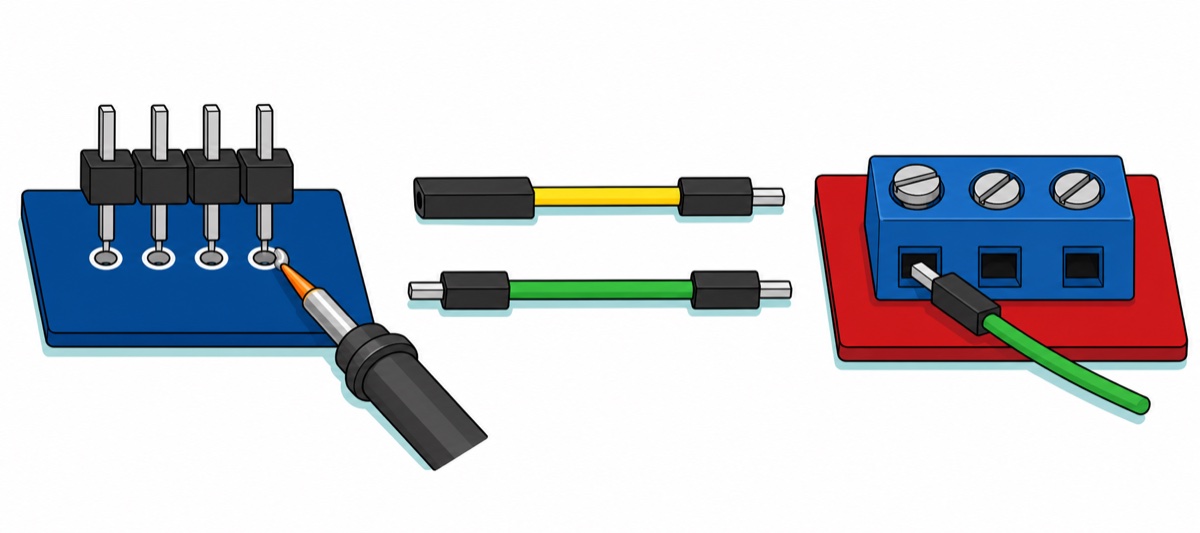
Two facts decide the jumpers, and neither is a pin number. The Uno‘s headers are female, so every wire ending there needs a male pin. The relay module’s control side is a three-way screw terminal marked IN, DC− and DC+, so those wires need a bare male pin at that end too, clamped under the screw — a male-to-male run. The ZK-VR01 gets pins snapped off a 40-pin strip soldered into its bare pads (see our header-soldering guide), so its run is male-to-female.
Only T goes to the Uno. R stays unconnected on purpose — this build only listens, which keeps you clear of the one direction worth thinking about. A module output into an Uno input is the safe direction whatever the module drives: the Uno reads HIGH above 0.6 × Vcc = 3.0 V, which a 3.3 V-class output clears and a 5 V one clears by more. The reverse is not symmetric — the Uno’s 5 V transmit into the module’s R pin is the direction that wants a divider, and this build never uses it.
| From | To | Jumper |
|---|---|---|
| ZK-VR01 5V | Uno 5V | M–F |
| ZK-VR01 GND | Uno GND | M–F |
| ZK-VR01 T | Uno D10 | M–F |
| ZK-VR01 R | not connected | — |
| ZK-VR01 pad A25 (top of the column) | Uno D2 | M–F |
| ZK-VR01 pad A26 | Uno D3 | M–F |
| ZK-VR01 pad A27 | Uno D4 | M–F |
| Uno 5V | Relay DC+ | M–M, under the screw |
| Uno GND | Relay DC− | M–M, under the screw |
| Uno D7 | Relay IN | M–M, under the screw |
How do you read the module before you write any code?
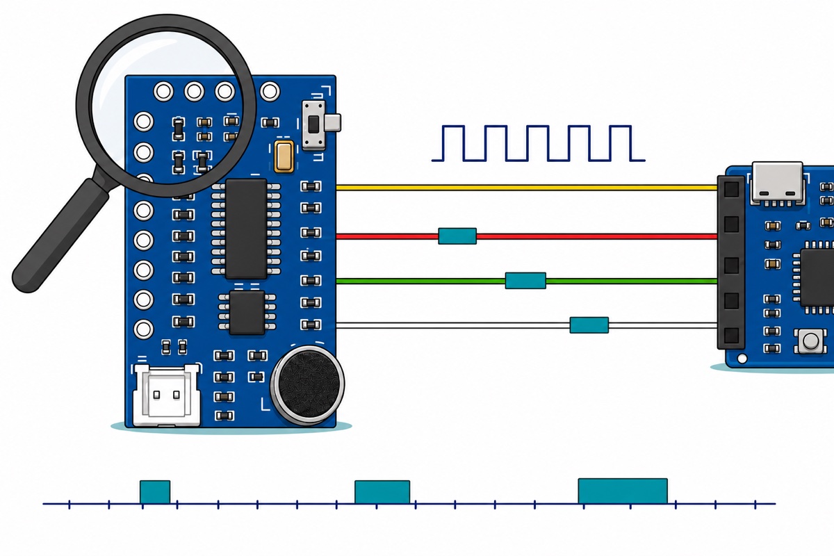
The ZK-VR01 answers this itself. The sketch below controls nothing: it cycles a software serial port on D10 through five common baud rates, timestamping both the bytes arriving on T and every edge on D2, D3 and D4. Speak one command per window, three times. Over fifty commands share eight pads, so three leads sample three of them: if bytes appear on T while no pad ever moves, the words you are saying live on pads you have not wired, so shift the leads down the column and go again.
Two answers fall out. The correct baud rate is the one where the same word gives the same bytes three times; wrong rates give noise or silence. And the timestamps say whether a recognition pulses the pad for a few tens of milliseconds or latches it until the next command — which decides the code you write next.
Read the pads with plain INPUT first, not INPUT_PULLUP: an input pin drives nothing at all, the only safe way to meet a pin whose direction you have not established. A pad that streams random edges is not faulty — nothing is driving it; add the pull-up and it goes quiet at a steady HIGH, while a driven pad keeps its transitions. The ATmega328P’s internal pull-up is 20–50 kΩ, so even if that pad is driven the other way the current is at most 5 V / 20 kΩ = 0.25 mA.
// ZK-VR01 DISCOVERY SKETCH - it controls nothing, it only watches.
// Wiring: module 5V -> Uno 5V, module GND -> Uno GND, module T -> Uno D10.
//         Module R is deliberately NOT connected.
//         Three command pads -> Uno D2, D3, D4.
// Open Serial Monitor at 115200, speak one command per listening window,
// and write down what your own board does. That table is the real output.

#include <SoftwareSerial.h>

const uint8_t PIN_VR_T  = 10;   // module T (its transmit pad) -> Uno D10
const uint8_t PIN_VR_R  = 11;   // SoftwareSerial needs a TX pin; leave this one unwired
const uint8_t PADS[]    = { 2, 3, 4 };
const uint8_t N_PADS    = sizeof(PADS) / sizeof(PADS[0]);

SoftwareSerial vr(PIN_VR_T, PIN_VR_R);

// The module's baud rate is not something to guess at - sweep it and look.
const long RATES[]      = { 9600, 19200, 38400, 57600, 115200 };
const uint8_t N_RATES   = sizeof(RATES) / sizeof(RATES[0]);
const unsigned long WINDOW_MS = 8000;   // long enough to repeat one command three times

uint8_t lastPad[N_PADS];
uint8_t rateIndex = 0;
unsigned long windowStart = 0;

void openWindow() {
  vr.end();
  vr.begin(RATES[rateIndex]);
  vr.listen();
  windowStart = millis();
  Serial.println();
  Serial.print(F("--- listening at "));
  Serial.print(RATES[rateIndex]);
  Serial.println(F(" baud - say one command now ---"));
  rateIndex = (rateIndex + 1) % N_RATES;
}

void setup() {
  // Plain INPUT, not INPUT_PULLUP: a high-impedance input drives nothing into
  // a pin whose direction we do not know yet. Only add a pull-up (below) once
  // the pad has proved it is an output.
  for (uint8_t i = 0; i < N_PADS; i++) {
    pinMode(PADS[i], INPUT);
    lastPad[i] = digitalRead(PADS[i]);
  }

  Serial.begin(115200);
  Serial.println(F("ZK-VR01 discovery. Bytes and pad edges are timestamped in ms."));
  openWindow();
}

void loop() {
  if (millis() - windowStart >= WINDOW_MS) {
    openWindow();
  }

  // Anything arriving on T, printed raw. Repeat the same word three times:
  // a correct baud rate gives you the SAME bytes three times.
  while (vr.available()) {
    uint8_t b = (uint8_t)vr.read();
    Serial.print(F("byte 0x"));
    if (b < 0x10) Serial.print('0');
    Serial.print(b, HEX);
    Serial.print(F("  '"));
    Serial.print((char)((b >= 32 && b < 127) ? b : '.'));
    Serial.print(F("'  @"));
    Serial.println(millis());
  }

  // Every pad edge, timestamped. Two edges close together means the pad
  // PULSES; one edge that never returns means it LATCHES. You need to know
  // which before you can write the relay code.
  for (uint8_t i = 0; i < N_PADS; i++) {
    uint8_t now = digitalRead(PADS[i]);
    if (now != lastPad[i]) {
      lastPad[i] = now;
      Serial.print(F("pad D"));
      Serial.print(PADS[i]);
      Serial.print(now ? F(" -> HIGH") : F(" -> LOW"));
      Serial.print(F("  @"));
      Serial.println(millis());
    }
  }
}
It compiles to 4,418 bytes of flash and 335 bytes of globals. Garbage at every rate is not a faulty module (silence at every rate is a different fault) — it is SoftwareSerial at its ceiling: its own source calibrates the receive timings to work up to 115200 baud on a 16 MHz AVR. Our HC-05 Bluetooth guide runs the same library at 9600, well inside that range. The library bit-bangs: a pin-change interrupt catches the start bit, then a calibrated busy-wait steps through the eight data bits. At 16 MHz and 115200 baud one bit lasts 16,000,000 / 115,200 ≈ 139 clock cycles, and that interrupt runs with further interrupts off, so nothing preempts it mid-byte. What hurts is the moment before: an interrupt already running when the start bit lands — Timer0 keeping millis() going, the hardware UART draining its buffer — delays entry into the handler, and every sample after it is late by a real fraction of a bit. At 9600 the same bit lasts 1,667 cycles and the identical delay is nothing. Hence the command pads’ equal billing: a pad has no baud rate to get wrong.
Why does the relay click on and straight back off?
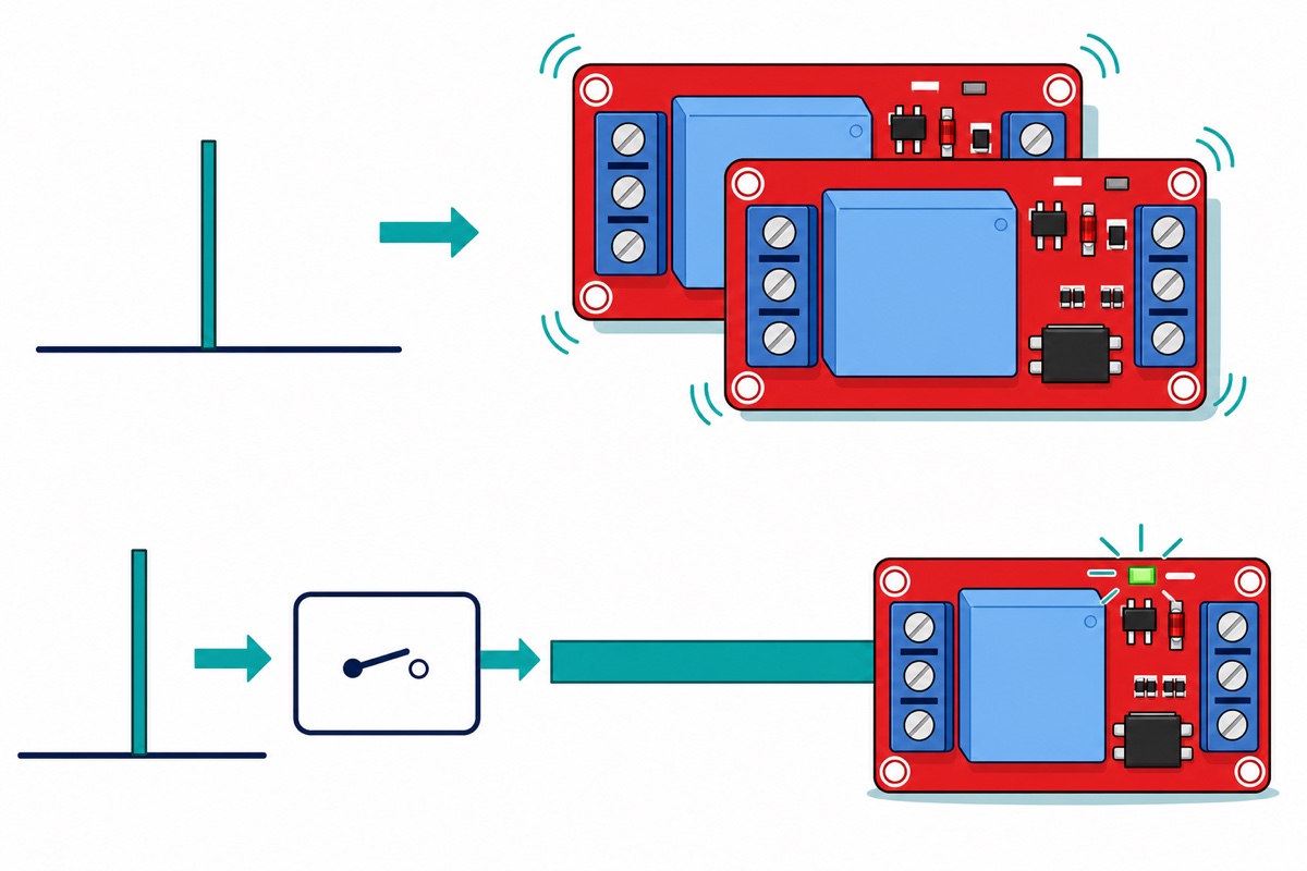
Because a recognition is an event and a relay is a state, and nothing converts one into the other by itself. The pad blips: active for a few tens of milliseconds, then back. Write digitalWrite(relay, digitalRead(pad)) and the relay copies the blip. A lamp must stay on after the sound stops.
So the pad’s edge sets a variable and the variable drives the pin. Below, two pads set and clear one boolean, and the pin is written only when that boolean changes.
// Voice-latched relay: ZK-VR01 command pads -> Arduino Uno -> 1-way relay module.
// Wiring: module 5V/GND -> Uno 5V/GND, two command pads -> Uno D2 and D3.
//         Uno 5V -> relay DC+, Uno GND -> relay DC-, Uno D7 -> relay IN.
// Fill in the four constants below from your own discovery run.

const uint8_t PIN_PAD_ON  = 2;    // pad that fired for your "on" command
const uint8_t PIN_PAD_OFF = 3;    // pad that fired for your "off" command
const uint8_t PIN_RELAY   = 7;    // Uno D7 -> relay module IN

const uint8_t PAD_ACTIVE  = LOW;  // level the pad went to on a recognition
const uint8_t RELAY_ON    = LOW;  // shunt on L as shipped = low-level trigger
const uint8_t RELAY_OFF   = HIGH;

const unsigned long DEBOUNCE_MS = 30;

struct Pad {
  uint8_t pin;
  uint8_t last;
  unsigned long changedAt;
};

Pad padOn  = { PIN_PAD_ON,  HIGH, 0 };
Pad padOff = { PIN_PAD_OFF, HIGH, 0 };

bool lampOn = false;

// A recognition is an EVENT: the pad moves, briefly. This returns true once
// per settled transition INTO the active level, and never while the pad simply
// sits there - which is what turns a blip into something you can act on.
bool firedOnce(Pad &p) {
  uint8_t now = digitalRead(p.pin);
  if (now == p.last) return false;
  if (millis() - p.changedAt < DEBOUNCE_MS) return false;   // still in lock-out
  p.last = now;
  p.changedAt = millis();
  return (now == PAD_ACTIVE);
}

void setup() {
  // Order matters. While the pin is still an input, digitalWrite() sets its
  // internal pull-up rather than a drive level, so the line is already held
  // high before pinMode() makes it an output. Do it the other way round and
  // the pin becomes an output at its reset value of LOW - which on a
  // low-level-trigger board means the relay snaps in on every upload.
  digitalWrite(PIN_RELAY, RELAY_OFF);
  pinMode(PIN_RELAY, OUTPUT);

  pinMode(PIN_PAD_ON, INPUT);
  pinMode(PIN_PAD_OFF, INPUT);
  padOn.last  = digitalRead(PIN_PAD_ON);
  padOff.last = digitalRead(PIN_PAD_OFF);

  Serial.begin(115200);
  Serial.println(F("ready - relay OFF"));
}

void loop() {
  bool sawOn  = firedOnce(padOn);
  bool sawOff = firedOnce(padOff);

  // A relay is a STATE. The events set and clear one boolean; the pin is only
  // written when that boolean actually changes, so repeats are harmless.
  bool wanted = lampOn;
  if (sawOn)  wanted = true;
  if (sawOff) wanted = false;

  // One command that toggles instead of two that set and clear? Replace the
  // two lines above with  if (sawOn) wanted = !wanted;  and add a hold-off of
  // a second or so, because one sentence can fire the pad more than once and
  // every extra fire would flip the state straight back.

  if (wanted != lampOn) {
    lampOn = wanted;
    digitalWrite(PIN_RELAY, lampOn ? RELAY_ON : RELAY_OFF);
    Serial.println(lampOn ? F("relay ON") : F("relay OFF"));
  }
}
That one compiles to 2,270 bytes of flash and 201 bytes of globals. If your discovery run produced a clean repeatable byte per command instead, keep everything below firedOnce() and swap the pad reads for a byte comparison.
The relay module’s PWR and LED1 indicators plus its audible click already prove the voice → Uno → relay chain works — which is why there is no load in the parts list. What goes on NO, COM and NC, and why 240 V mains is not a hobby job, is the subject of our relay module safety guide. Keep this build to low-voltage DC — and note that a 12 V signal light, fan or 2 A adaptor each bring their own crimps and sockets.
Common mistakes we see from real customers
The module goes on D0 and D1. Those pins are the Uno’s hardware UART, shared with the USB bootloader and the Serial Monitor, so uploads fail or debug output turns to nonsense. Use any other pair.
A jumper is only resting in an unsoldered pad. The holes are bare, and a dupont pin pushed into one connects intermittently at best. Solder first: a joint that is not one imitates every fault on this page.
The relay clicks in the instant the Uno resets. That is pinMode(OUTPUT) running before the first digitalWrite(). Reverse the two lines.
A bare relay is wired straight to a pin. It clicks weakly or not at all, and often takes the pin with it: 71 mA through a 20 mA pin with no flyback diode is two faults at once.
Nothing arrives on T at any baud rate. Check the board’s own OFF/ON slide switch first, then move to the command pads, which no baud rate can defeat.
FAQ
Do I have to solder the ZK-VR01?
Yes. Both rows arrive as bare plated through-holes, so a 2.54 mm male header has to go in first. The parts list includes a 40-pin strip to snap pieces from, or add the 10-pin soldering service and we fit it.
Can I use the command pads without any serial code?
Yes, and it is the more forgiving lane. A pad is just a digital line: one wire per command into a digital input, read with digitalRead(). No baud rate is involved, so the SoftwareSerial timing above cannot bite you.
Can I choose my own command words?
The ZK-VR01’s command set is built into its firmware. If defining your own wake word is the point, the ASR-PRO module is the one to reach for: its command set is user-programmable, at a higher price.
What is the speaker in the bag for?
The white two-pin SPK socket drives the speaker in the bag. Use it as your first bench check: run the module from 5 V and GND alone, switch it ON and speak, and whatever it does then it does without the Uno.
Can this switch a mains lamp?
Not in this guide — keep everything here to low-voltage DC. The contacts are rated higher, but wiring 240 V is licensed work in Malaysia, and our relay module safety guide covers it properly.
The habit outlasts the project. Any module with a serial pad or a row of unlabelled IO can be met this way: watch first, write down what it does, then code against that.
Last updated August 2026. Stuck? Chat with us on WhatsApp.
