

Tutorials
TDS Water Quality Meter with Arduino: Test Tap, Filter and Aquarium Water
Aug
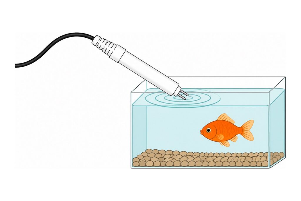
The most useful water quality meter in a home is the one you can carry from the tap to the aquarium. Connect a TDS probe to an Arduino Uno through its measuring board, show the ppm reading on a 0.96-inch OLED, and you can compare tap water, filter output and aquarium water in a few seconds each. There is one small solder job you cannot skip — we show you where and why.
What does a TDS sensor actually measure?
A TDS (Total Dissolved Solids) sensor does not count particles one by one — it measures how easily an electric current flows through the water. Dissolved salts and minerals break apart into ions, and those ions carry the current between the two electrodes of the TDS probe: more ions means higher conductivity, and the board converts that conductivity into an estimate of total dissolved solids in ppm (mg per litre). Pure water barely conducts at all.
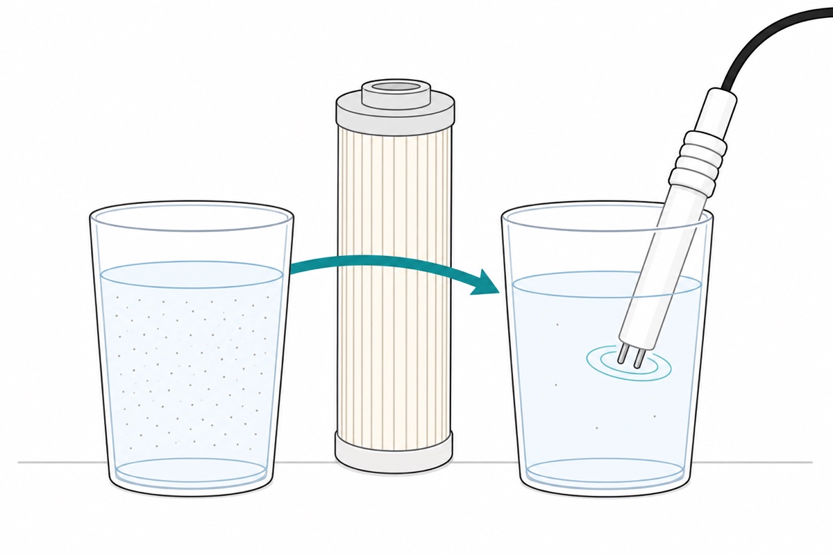
Understand what it does not see, too. Bacteria, chlorine and most organic matter barely change conductivity, so a low reading is not confirmation the water is safe to drink, and a high reading does not mean poison — mineral water is deliberately sold at hundreds of ppm, while RO water reads near zero because its membrane rejects ions. That is why a single number means less than the difference between two readings: tap versus filter output answers “is my filter still working?” with a number instead of a guess.
| The reading you see | What it means | What it does NOT mean |
|---|---|---|
| Near 0–50 ppm at an RO output | The RO membrane is rejecting almost all dissolved minerals — the filter is working | No guarantee it is germ-free; bacteria are invisible to this meter |
| Carbon filter output ≈ same as tap | Normal — carbon filters target chlorine, taste and smell, not dissolved solids | Not proof your carbon filter is broken |
| Hundreds of ppm in mineral water | The minerals are the product — dissolved in on purpose | Not a sign the water is dirty or dangerous |
| Aquarium TDS climbing week after week | Solids are accumulating: leftover food, waste, and evaporating water leaving its minerals behind | No substitute for ammonia or pH tests — it is a signal that a water change is due |
Our other water guides measure its level — like the JSN-SR04T tank monitor — or pump it around, like the automatic plant watering system. This is the first build that puts a number on the water itself.
Parts list — the TDS probe, the Uno that reads it, and an OLED for the ppm display
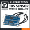 TDS Water Quality Sensor Module Liquid Detection Meter Testing Equipment for Arduino DIY Projects
 Arduino Uno Compatible SMD UNO R3 with Type B Cable - ATMEGA328P with CH340G-Microcontroller Project
 0.96‘ OLED Display Module Blue White Screen I2C IIC Serial 128X64 LCD Display Board - 0.96' OLED WHITE
 2.54mm Pin Header Female Male Single Row Header 40P Connector Black White Red Yellow Green Blue - 40P MALE HEADER (BLACK)
 40pcs Dupont Wire 10cm 20cm 30cm for Breadboard DIY Experiment Jumper Wire Breadboard wire - DUPONT WIRE M-F 20CM
Parts list
| Item | Price | Qty | |
|---|---|---|---|
 Soldering Service for Circuit Boards & Electronics - 5 Pins Soldering ServiceSOLSE05 Soldering Service for Circuit Boards & Electronics - 5 Pins Soldering ServiceSOLSE05 | RM0.80 |
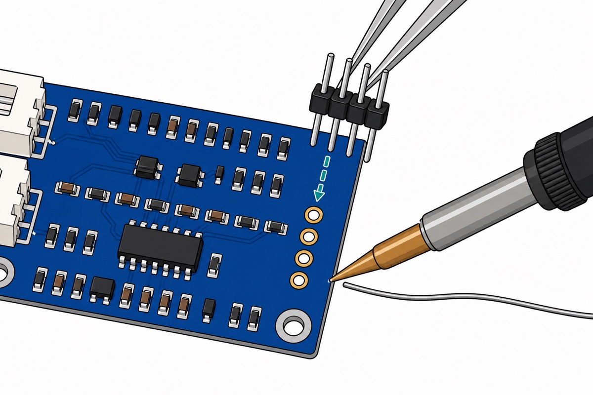
The TDS board arrives with four bare A0/T1/−/+ pads and no headers in the box. Add the 5-pin soldering service and we solder a 4-pin header section onto those pads for you — message us on WhatsApp first so we know it is for this TDS board.
What is in the box — and what must be soldered?
Our TDS Water Quality Sensor module arrives as two pieces: a blue measuring board marked TDS BOARD V1.0, and a white cylindrical probe with two pin electrodes at its tip, its waterproof black cable ending in a white JST-XH plug that fits the 2-pin socket on the board’s left edge. The 3-pin JST-XH socket below it is the output socket — its cable is not included, so our route is the row of four pads labelled A0, T1, − and + on the board’s right edge, each clearly marked on the silkscreen.
All four pads arrive as empty holes with no header fitted, and there is no header strip in the box — so soldering comes first. Snap a 4-pin section off a 40-pin male header strip, seat it in the A0/T1/−/+ pads, and solder from the back; our header pin soldering guide covers the technique step by step. Rather not hold a soldering iron? The optional row in the parts list above takes care of it.
Why does the TDS board “shake” the probe with AC?
The CD4060BM chip on the board is an oscillator — it drives the probe with alternating voltage (AC), not DC, and here hides the reason this probe cannot be read with two wires straight into an analog pin. DC current flowing through water pulls ions to the electrodes and builds a charged layer on their surface — polarisation — which chokes the current harder and harder, so the reading drifts downward without end. AC excitation reverses direction too fast for that layer to form. The LMV324A chip beside it then converts the probe signal back into a smooth DC voltage the A0 pin can read.
The working numbers: this TDS board runs on a 3.3–5.5 V supply, draws 3–6 mA, and outputs 0–2.3 V analog across a 0–1000 ppm measuring range, with ±10% full-scale accuracy at 25 °C. That voltage becomes ppm through the manufacturer’s polynomial — (133.42V³ − 255.86V² + 857.39V) × 0.5 — and the V in that formula should be temperature-compensated voltage, because ions move more freely in warmer water — conductivity rises roughly 2% for every degree Celsius. The T1 pad is the input for a temperature probe; we leave it empty and fix 25 °C in code, so cooler water reads slightly low and warmer water slightly high. For comparison work — tap versus filter, this week versus last — compare water at similar temperatures and this limitation all but disappears.
How do you wire the TDS board and OLED to the Uno?
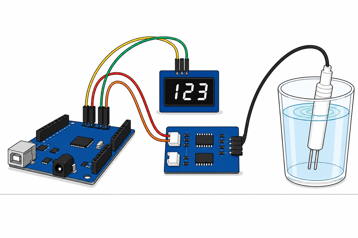
That freshly soldered 4-pin header, together with the male header that arrives pre-fitted on the 0.96-inch OLED, makes the wiring pure male-female jumper work — no breadboard: female ends onto the module pins, male ends into the Uno‘s female header sockets. If all you have on hand are male-male jumpers, a breadboard bridges the gender gap.
| Module pin | Uno pin | Why |
|---|---|---|
| TDS + | 5V | Board supply — 3.3–5.5 V range; 5 V matches VREF in the sketch |
| TDS − | GND | Either of the two GND sockets on the POWER header |
| TDS A0 | A0 | The 0–2.3 V analog output the sketch reads |
| TDS T1 | — | Temperature probe input — left empty; compensation is done in code at 25 °C |
| OLED GND | GND | This module’s header is GND-first: GND VCC SCL SDA |
| OLED VCC | 3.3V | This SSD1306 module runs happily on 3.3–5 V |
| OLED SCL | A5 | The Uno’s I2C clock (or the SCL socket at the end of the R3 digital header) |
| OLED SDA | A4 | The Uno’s I2C data (or the SDA socket) |
Note the GND-first header order on the OLED — GND VCC SCL SDA, the reverse of the VCC-first habit most other modules teach, and wiring it by habit is the classic way to burn one. One safety rule stands for the whole project: everything here is low-voltage DC, but water and electronics are still not friends — unplug the USB cable every time you move, fill or pour water near this build.
What does the TDS meter sketch look like?
Install the Adafruit SSD1306 library from the Library Manager and let the IDE pull in Adafruit GFX alongside it. One decision in this code is worth understanding: raw readings are filtered with a median, not an average. AC excitation and a moving water surface produce occasional spikes in the ADC readings — an average lets one spike drag the whole reading, while a median throws it straight out.
// Portable TDS meter: TDS Board V1.0 on A0, SSD1306 OLED on the I2C bus.
// The ppm reading on the screen updates roughly once a second.
#include <Wire.h>
#include <Adafruit_GFX.h>
#include <Adafruit_SSD1306.h>

Adafruit_SSD1306 oled(128, 64, &Wire, -1);

const uint8_t PIN_TDS = A0;     // TDS board A0 pad -> Uno A0 pin
const float   VREF    = 5.0;    // board powered from the Uno's 5V pin
const uint8_t N       = 30;     // median buffer size

int   sampel[N];                // raw ADC readings
uint8_t idx = 0;

// Water temperature assumed fixed at 25 deg C - the T1 pad is not connected,
// so temperature compensation is done in code at this fixed value.
const float SUHU_AIR = 25.0;

// A median filters the occasional spikes from the board's AC excitation
// far better than a plain average does.
float median(int *d, uint8_t n) {
  int t[N];
  for (uint8_t i = 0; i < n; i++) t[i] = d[i];
  for (uint8_t i = 0; i < n - 1; i++)          // simple insertion sort
    for (uint8_t j = i + 1; j < n; j++)
      if (t[j] < t[i]) { int s = t[i]; t[i] = t[j]; t[j] = s; }
  if (n & 1) return t[n / 2];
  return (t[n / 2 - 1] + t[n / 2]) / 2.0;
}

void setup() {
  Serial.begin(9600);
  if (!oled.begin(SSD1306_SWITCHCAPVCC, 0x3C)) {  // this module answers at 0x3C
    Serial.println("SSD1306 not found at 0x3C - check wiring");
    while (true) delay(100);
  }
  oled.setTextColor(SSD1306_WHITE);
  for (uint8_t i = 0; i < N; i++) sampel[i] = analogRead(PIN_TDS);
}

void loop() {
  static unsigned long tSampel = 0, tPapar = 0;

  // Take one reading every 40 ms into the circular buffer
  if (millis() - tSampel >= 40) {
    tSampel = millis();
    sampel[idx] = analogRead(PIN_TDS);
    idx = (idx + 1) % N;
  }

  // Compute and display once per second
  if (millis() - tPapar >= 1000) {
    tPapar = millis();

    float v = median(sampel, N) * VREF / 1024.0;   // ADC -> volts

    // Temperature compensation: water conductivity rises ~2% per deg C.
    // With SUHU_AIR = 25.0 this coefficient = 1.0 (no correction).
    float pekali = 1.0 + 0.02 * (SUHU_AIR - 25.0);
    float vKompensasi = v / pekali;

    // Voltage -> ppm conversion polynomial from the board manufacturer
    float ppm = (133.42 * vKompensasi * vKompensasi * vKompensasi
               - 255.86 * vKompensasi * vKompensasi
               + 857.39 * vKompensasi) * 0.5;
    if (ppm < 0) ppm = 0;

    Serial.print("V=");
    Serial.print(v, 3);
    Serial.print("  TDS=");
    Serial.print(ppm, 0);
    Serial.println(" ppm");

    oled.clearDisplay();
    oled.setTextSize(1);
    oled.setCursor(0, 0);
    oled.print("TDS");
    oled.setCursor(98, 0);
    oled.print(v, 2);
    oled.print("V");
    oled.setTextSize(3);                 // big digits, readable from a distance
    oled.setCursor(10, 22);
    oled.print(ppm, 0);
    oled.setTextSize(1);
    oled.setCursor(104, 36);
    oled.print("ppm");
    oled.display();
  }
}
It compiles to 16,746 bytes — half the Uno’s sketch space. The SUHU_AIR line is deliberately a variable rather than a buried number: at 25 °C its coefficient is exactly 1.0, and whoever later adds a temperature probe to the T1 pad only has to swap that one value for a real reading.
How do you use the ppm readings at home?
A TDS meter is at its most powerful as a comparison tool, so start with a baseline: dip the probe tip into a glass of tap water, wait for the number to settle, and write it down. Then a second glass from the filter output — an under-sink RO unit should drop sharply against tap, an outdoor carbon filter reads nearly the same, and both outcomes are normal per the interpretation table above. For an aquarium, one logged reading a week is a trend you can trust: evaporating water leaves its minerals behind, food waste accumulates, and a rising line is the early signal that a partial water change is due.
Dipping technique comes down to three simple rules. Dip the probe tip only — the water level stays below the ribbed collar, and the cable joint never touches water. Hold the probe still, away from filter bubbles and pump flow, because moving water shakes the reading. After each sample, rinse the probe in clean water and dry it, so residue from a salty sample cannot inflate the next one.
Common mistakes we see
Wiring the probe straight to an analog pin without the board. Two wires into water do produce a reading — one that drifts downward without end while DC polarisation chokes the current at the electrode surfaces. The board’s AC excitation is what makes the reading stable; a probe without its board is not a meter.
Wiring the OLED VCC-first out of habit. This display’s header is GND VCC SCL SDA — ground first. Read the silkscreen every time before powering up, because a reversed supply can end the module for good.
Dunking the whole probe until the collar goes under. Only the electrode tip needs to be in the water. The collar and cable joint stay above the waterline — the waterproofing is designed for dipping, not full immersion.
Comparing fridge-cold water against room-temperature tap water. Conductivity rises about 2% per degree Celsius and the code fixes the temperature at 25 °C, so cross-temperature comparisons lead to misleading conclusions. Let the cold sample reach room temperature first. If you would rather have the compensation follow the real water temperature instead of the fixed 25 °C, measure it with a waterproof DS18B20 probe and feed that reading into SUHU_AIR.
Treating the reading as a final verdict on water quality. This meter is a hobby-grade estimator with ±10% full-scale accuracy — meaning the percentage is taken at the top of the 1000 ppm range, not at your current reading, so the deviation can reach ±100 ppm anywhere on the scale. That deviation is mostly systematic on the same probe, which is why trends and comparisons stay trustworthy — but it is not a drinking-water certification tool.
FAQ
Does a low TDS reading mean the water is safe to drink?
No. TDS only estimates dissolved solids through conductivity — bacteria, viruses and chlorine barely change it, so contaminated water can read low and perfectly good mineral water can read high. Use the readings to monitor filters and aquarium trends, not as a safety verdict.
Why is my TDS reading unstable?
The usual causes: the probe is moving, air bubbles are clinging to the electrodes, or the sample was taken right in a pump or filter stream. Hold the probe still in calm water and give it a few seconds — the median in the sketch filters out occasional spikes, but it cannot fix water that never stops churning.
Can I use this meter for a saltwater aquarium?
Not really. Seawater sits around 35,000 ppm, far beyond this board’s 0–1000 ppm measuring range, so the reading saturates and means nothing. For freshwater aquariums, fish ponds and household filters, that range lands right in the middle of the job.
Do I need to calibrate this TDS sensor?
For comparison work — tap versus filter, this week versus last — no: the manufacturer’s polynomial in the sketch is enough, and the ±10% full-scale accuracy applies equally to both sides of the comparison. Calibrating against a reference solution only pays off if you need absolute numbers you can compare with other meters.
Can I leave the probe permanently submerged in the aquarium?
Don’t. This probe is designed for brief dips: measure, remove, rinse and dry. Continuous immersion speeds up electrode erosion and shifts the readings over time — and one reading a week is already enough for a useful aquarium trend.
Water quality stops being guesswork the moment it becomes a number you logged yourself. Solder those four pins, dip the probe tip, and the next time someone asks whether the house filter still works, your answer is two readings — before and after.
Last updated August 2026. Stuck? Chat with us on WhatsApp.
