

✅ Ready Stock in KL(Sungai Besi)
🔥 Ship within 24 hours from KL on working hours | Monday to Saturday, ( 10:00 AM to 6:00 PM ), Closed on Sunday
🚚 Same Day Delivery Available For Klang Valley Customers.
☎️ Message us via Shopee Chat or Whatsapp +6011 – 6822 6855 to arrange same day delivery or for product enquiry
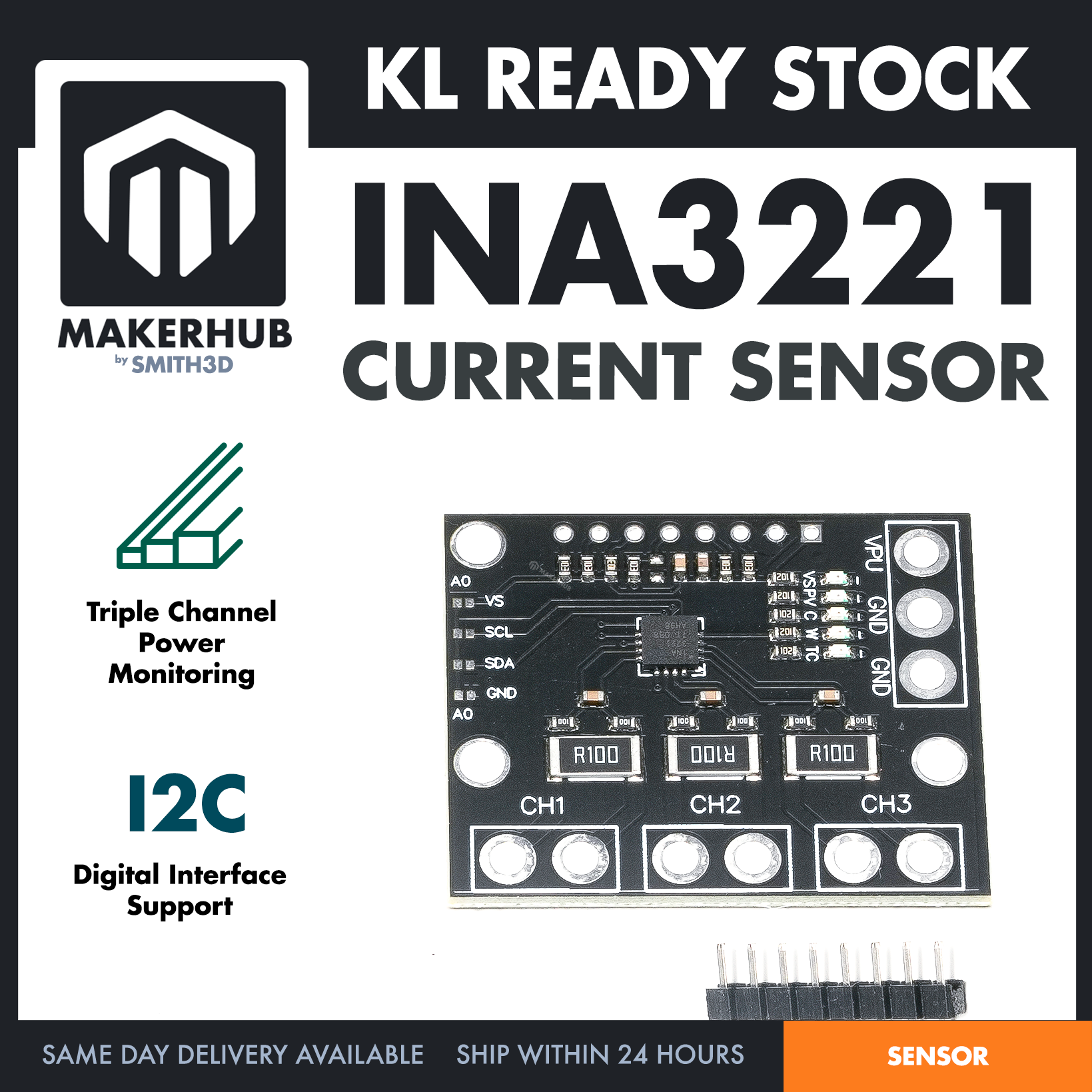
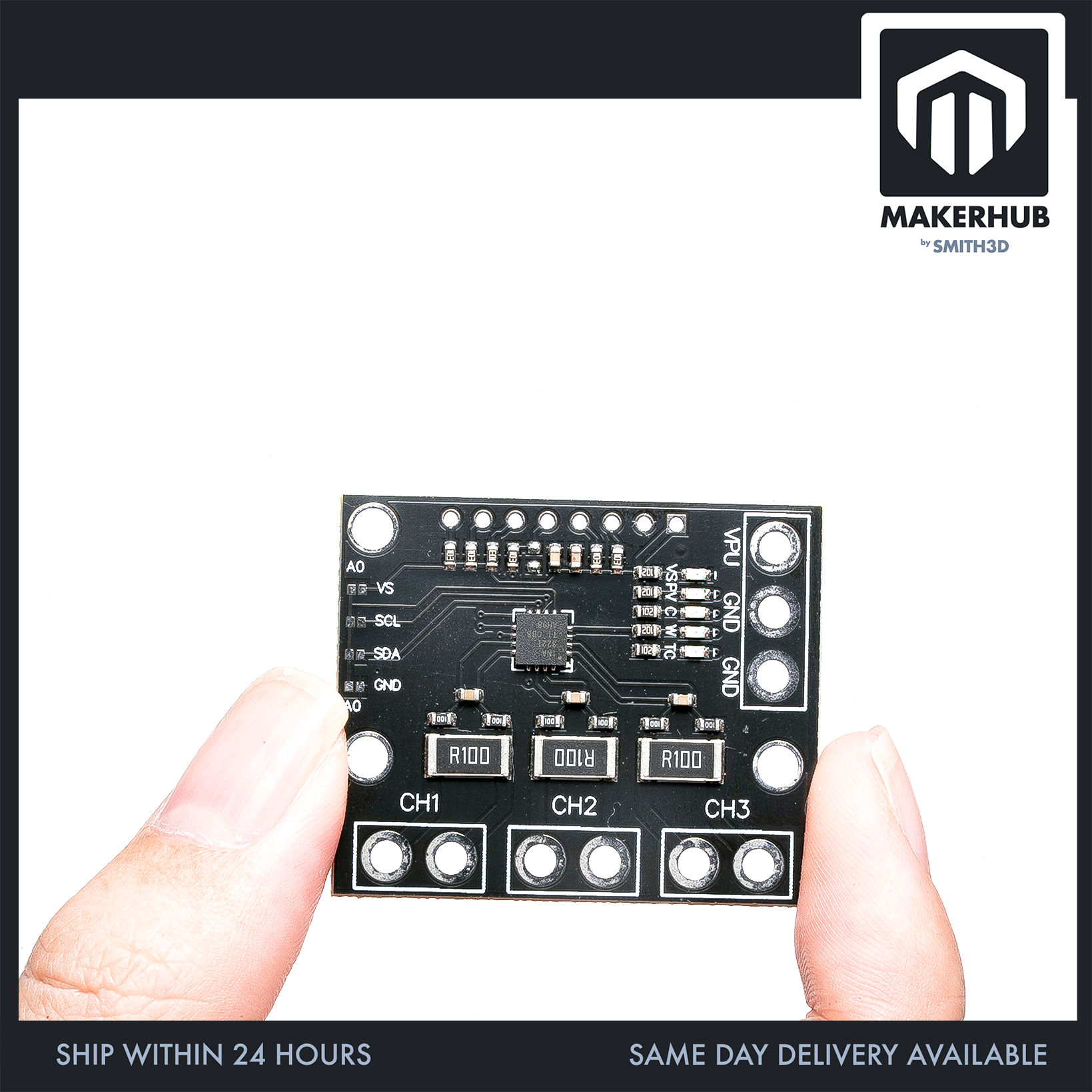
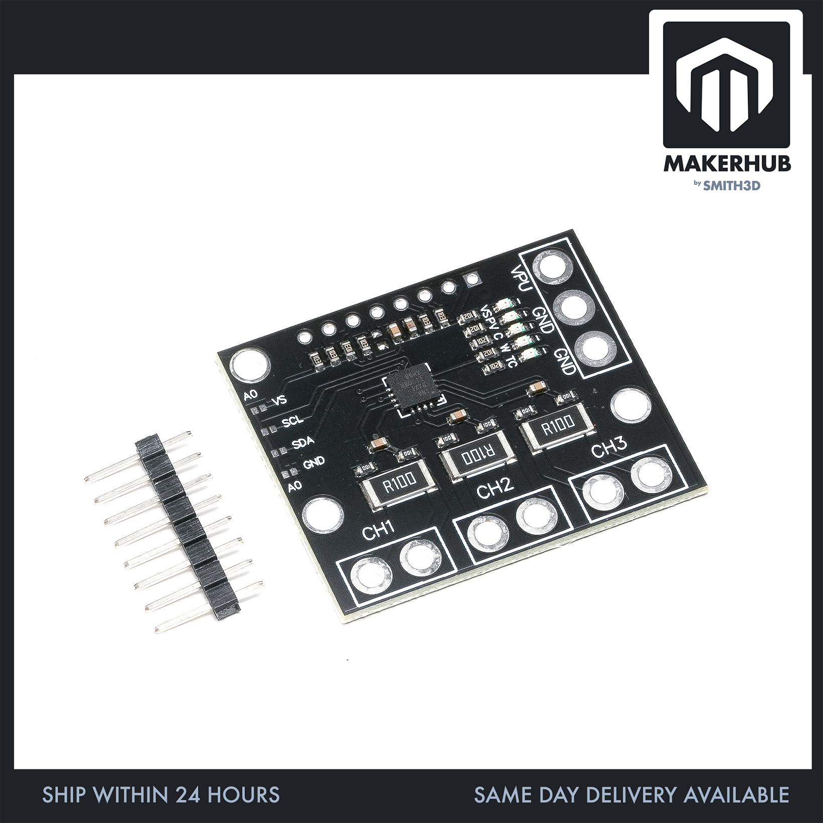
This is an INA3221 triple-channel current and voltage sensor module — one small black breakout board carrying three independent measurement channels, silkscreened CH1, CH2 and CH3, read over I2C by an Arduino, a Raspberry Pi or another I2C host. Each channel has its own shunt resistor and its own pair of terminal holes, so three separate rails or loads each get their own measurement path on one board.
⭐ Specification
– Channels: 3 independent channels, silkscreened CH1, CH2 and CH3. Each channel has its own shunt resistor and its own dedicated pair of terminal holes along the bottom edge.
– Shunt resistor: marked R100 = 0.100 Ω (100 mΩ), one per channel. All three are identical.
– Channel input parts: two series resistors marked 100 (10 Ω) per channel, sitting between the shunt and the IC, plus one small unmarked SMD part above each shunt.
– Interface: I2C.
– Address select: an A0 solder-jumper block on the left edge with four pad pairs — VS, SCL, SDA, GND — so the A0 pin can be tied four ways.
– Five marked positions — VS, PV, C, W, TC — along the right side, each with its own series resistor marked 102 (1 kΩ) and its own small white SMD part.
– VPU / GND / GND block: three large plated holes on the right edge, inside their own white outline box.
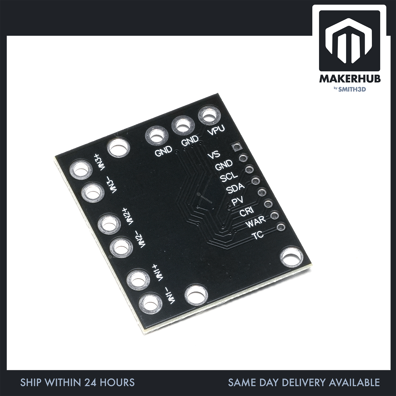
– Header row: a single row of 8 plated through-holes along the top edge — 7 round pads plus 1 square pad. The square pad is the pin-1 marker, at the right-hand end of the row as the board is photographed.
– Load-side holes: the three channel pairs and the VPU/GND/GND block use noticeably larger holes on a wider spacing than the top header row — they are wire and terminal-block scale, not header scale.
– IC: one small leadless (QFN-style) chip at board centre. It is the only IC on the board.
– Board: black PCB, landscape rectangle, three mounting holes.
🔌 Connector & What Ships
Read this part before you buy.
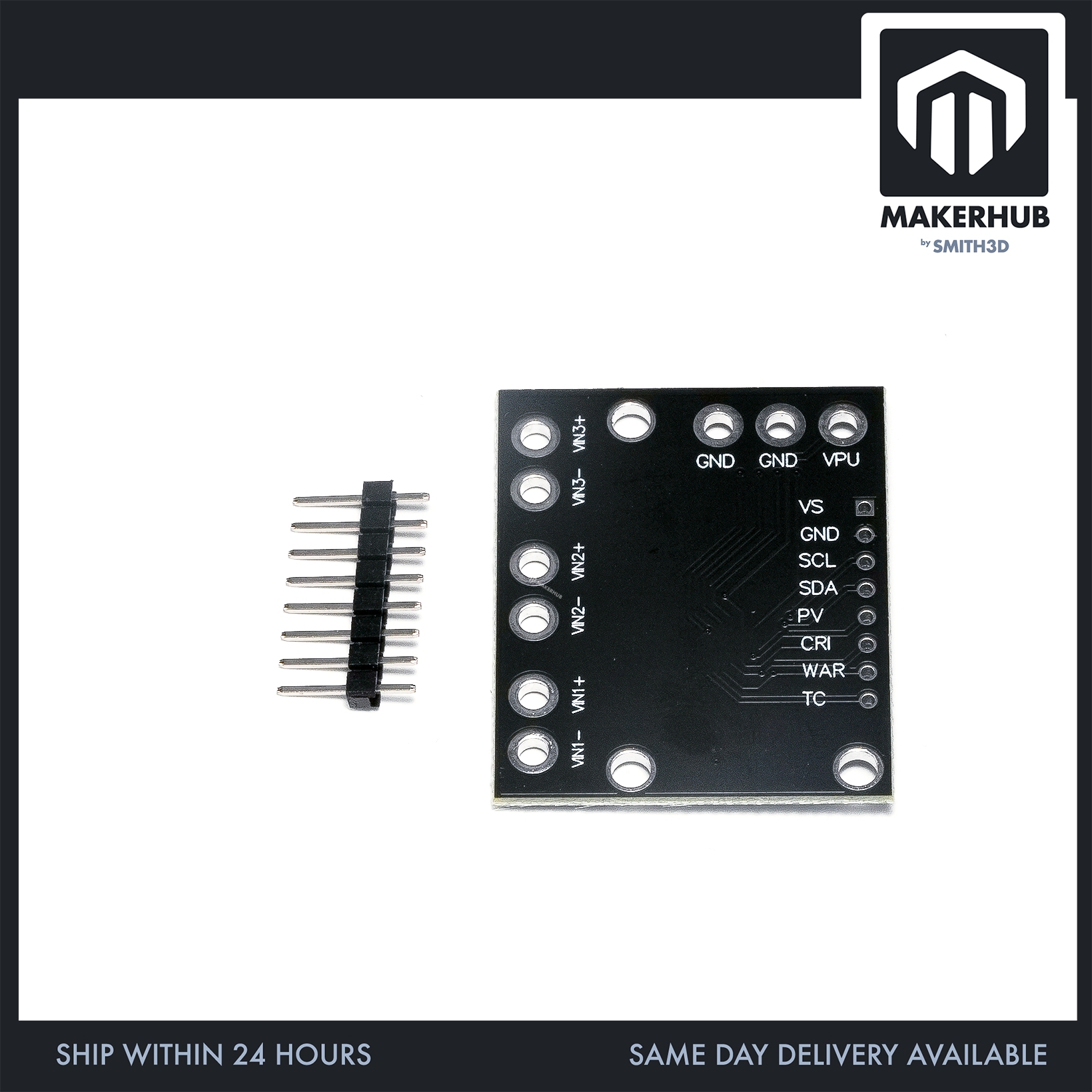
– Nothing is pre-soldered. All 17 plated holes on the board are bare — 8 on the top header row, 6 on the three channel pairs, 3 on the VPU/GND/GND block. No headers fitted, no screw terminals fitted, no wires attached.
– One connector is supplied, loose: a straight MALE pin-header strip, 8 pins. The pins stand up out of a black plastic body; there are no sockets or receptacles on it. Eight pins for the eight-hole top row.
– The strip is snapped off a longer strip, so one end carries an extra plastic position with no pin in it.
– The six CH1/CH2/CH3 holes and the three VPU/GND/GND holes get no connector at all. You solder your own wire or your own terminal block into them.
– Soldering is required. There is no solderless way to use this board as it ships.
⚒️ Interesting Project
1. Smart Battery Monitor: Create a battery health tracking system
2. Solar Panel Efficiency Tracker: Monitor solar panel performance
3. Multi-Device Power Consumption Logger: Track power usage of different devices
4. Robot Power Management System: Monitor motor power consumption
📦 Package Includes:
– 1x INA3221 triple-channel current/voltage sensor module — black PCB, nothing soldered into any of its 17 plated holes
– 1x straight male pin-header strip, 8 pins, loose and unsoldered
No jumper wires are included. No terminal blocks or screw terminals. No standoffs or screws. No cable.
🧰 What You Also Need
– A soldering iron and solder. Not optional — the board arrives with every hole bare.
– Jumper wires with a female end on the module side. Once you solder the supplied strip onto the top row, the module presents male pins there, so the wire that lands on the module needs a female socket on that end.
– Wire for the load side. The CH1/CH2/CH3 pairs and the VPU/GND/GND block have no connector supplied, so bring your own wire and solder it in directly.
– Or your own terminal block, if you would rather not hard-solder wire into the channel pads.
❓ FAQ
Q: Do I need to solder anything?
Yes. Every one of the 17 plated holes ships bare, and the one header strip supplied is loose, not fitted. Plan for soldering before you order.
Q: Does the supplied header cover the whole board?
No. The 8-pin strip covers the 8-hole top row only. The six CH1/CH2/CH3 holes and the three VPU/GND/GND holes have no connector supplied — those you wire yourself.
Q: Is the supplied header male or female?
Male. The pins protrude from the plastic body; there are no sockets on it. So after you solder it down, the module presents male pins to your jumper wires.
Q: Where is pin 1 on the top row?
The square pad marks it. Seven pads on that row are round and one is square — the square one is pin 1.
Q: Can I set the I2C address?
The board brings the A0 pin out to a solder-jumper block on the left edge with four pad pairs — VS, SCL, SDA and GND — so you pick which of the four A0 sits on.
Q: What shunt value is on each channel?
0.100 Ω (100 mΩ) — the part marked R100 sitting directly above CH1, CH2 and CH3. All three channels carry the same value. Size the wire you solder into the channel pads for the load you intend to run.
Q: Can I monitor three separate loads with one board?
Each of the three channels is independent — its own R100 shunt, its own dedicated pair of terminal holes — so each load gets its own measurement path on the board.
🏬 | Our Shop Lot |
No 12 (Ground Floor – 3D Printer & Parts) & (First Floor – Robotic Parts & Tools)
Jalan Tasik Utama 7,
Medan Niaga Tasik Damai,
Sungai Besi, 57000 Kuala Lumpur
| Weight | 0.05 kg |
|---|---|
| Dimensions | 5 × 5 × 2 cm |
Only logged in customers who have purchased this product may leave a review.
Related products
Sensor
GY-521 Gyroscope Accelerometer Module MPU6050 MPU-6050 Motion Measurement Drone Robotic Application
GY-521 GYRO ACCELE
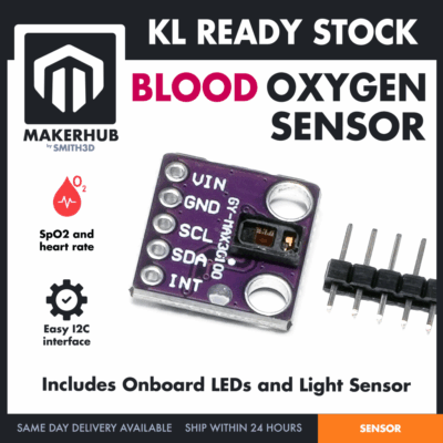
GY-MAX30102 BLOOD OXYGEN SENSOR
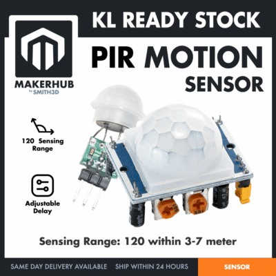
HC-SR501 PIR MOTION SENSOR

KY-037 SOUND SENSOR
WATER LEVEL SENSOR
Reviews
There are no reviews yet.