

Tutorials
DS18B20 Waterproof Probe with Arduino: Aquarium Water Temperature Monitor
Aug
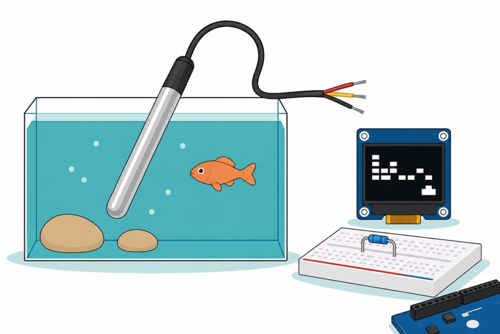
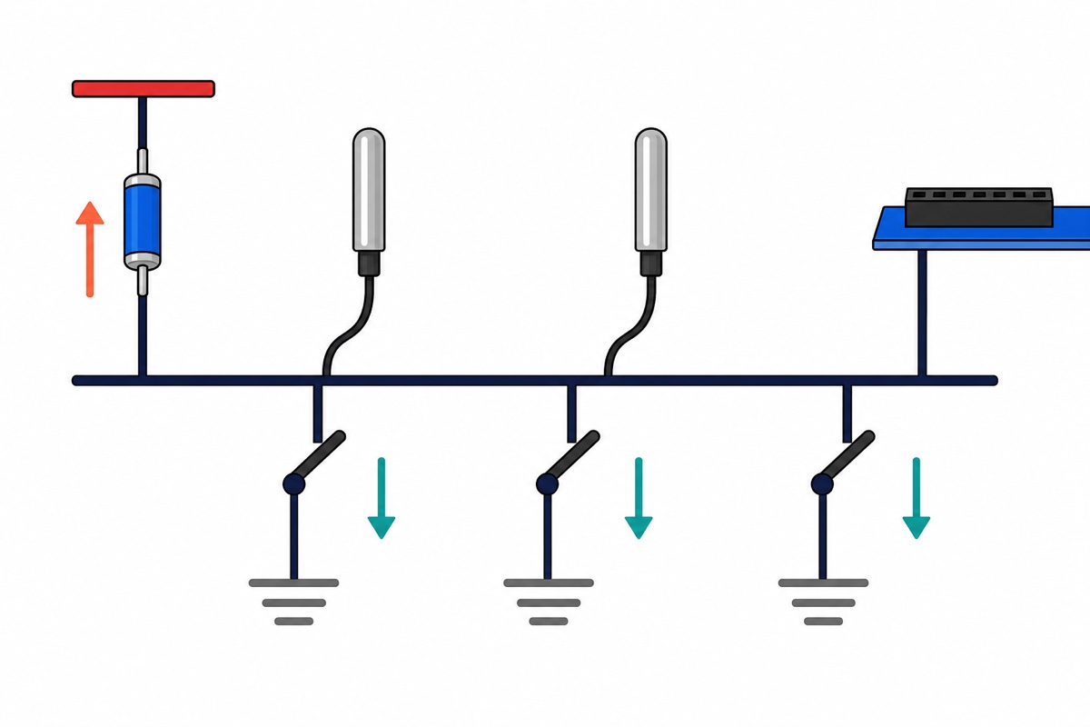
A waterproof DS18B20 reads water temperature through a single Arduino pin: red to 5 V, black to GND, yellow to D2, and one 4.7 kΩ resistor from that yellow line up to 5 V. The resistor is not a refinement: on a 1-Wire bus it is the only thing that can pull the line high, so without it the probe never answers at all — the bus scan finds nothing.
What do you need to monitor aquarium water temperature with an Arduino?
The DS18B20 waterproof probe is a stainless-steel capsule roughly 6 mm across on a one-metre black lead that ends in three bare stranded tails — red, yellow and black. That one metre is the build’s constraint: it reaches from the water to a dry spot beside the tank, no further. The rest of the list gives it a host, a readout, and that one resistor.
Parts list — DS18B20 aquarium water temperature monitor with OLED readout
 Temperature Sensor DS18B20 Temperature Measurement Probe WaterProof 18B20
 0.96‘ OLED Display Module Blue White Screen I2C IIC Serial 128X64 LCD Display Board - 0.96' OLED WHITE
 Arduino Uno Compatible SMD UNO R3 with Type B Cable - ATMEGA328P with CH340G-Microcontroller Project
 MB102 Breadboard 170 400 830 Holes Breadboard Donut Board Arduino Prototype Multi Color - BREADBOARD (400 HOLES)
 40pcs Dupont Wire 10cm 20cm 30cm for Breadboard DIY Experiment Jumper Wire Breadboard wire - DUPONT WIRE M-M 20CM
 400 pcs 1/4W Resistor Pack Resistor Kit 20 Common Value with 20 each
Optional — a second probe, and a USB cable if you need one
 Data Cable Type-A Type-C MicroUSB Type-B 0.5m 1m 30cm 0.3m 100cm Data Transfer Upload Code - TYPE-A TO TYPE-B (1.0M)
A second DS18B20 shares the same pin and the same single pull-up resistor, which is what you want for water-in versus water-out, or two tanks on one board. The USB A-to-B cable is the lead the Uno's full-size square socket takes — add one if you do not already have that shape in your drawer.
Connector shape decides whether these parts meet. The 0.96-inch white OLED arrives with its four-pin male header soldered on and silkscreened GND, VCC, SCL, SDA — ground first, worth reading off the board rather than assuming, since its neighbour is 5 V. That header plugs into the 400-point breadboard, and male-to-male jumpers carry each row to the female sockets on the Uno. The probe has no plug at all: its three tails go straight into breadboard holes.
Why does the DS18B20 need a 4.7 kΩ pull-up resistor?
The DS18B20’s data pin is open drain: inside the probe, DQ connects to a transistor that can pull the line down to ground and to nothing that can push it up. The Arduino’s pin behaves the same way while it is talking. So on a 1-Wire bus every participant is able to create a logic low and none of them can create a logic high — the resistor up to 5 V is the entire mechanism by which the line ever rises. Leave it out and the line simply floats — no idle high, no reset pulse, no reply.
The datasheet turns that into a deadline. To send a 1, the master pulls the line low, releases it, and the line must be back at a valid high within 15 µs of the start of the time slot. Resistor and bus capacitance form an RC charging curve, so that deadline is a resistance budget. A one-metre probe lead plus a breadboard row is on the order of 100 pF: 4.7 kΩ × 100 pF is a 0.47 µs time constant, so the line recovers in about a microsecond — fifteen times inside the window. Ten kilohms doubles that to roughly two microseconds, which is exactly why one probe on one metre of cable does work on 10 kΩ. Add probes and metres and the capacitance climbs; near 1.5 nF the 10 kΩ curve is only two thirds of the way up when the 15 µs deadline passes and bits drop, while 4.7 kΩ still arrives with margin.
So the purchase answer is one 4.7 kΩ, 1/4 W resistor for the entire bus — one piece, not one per probe, because the probes hang off the same line in parallel. It has no polarity, so orientation does not matter. Out of a mixed pack, 4.7 kΩ reads yellow-violet-black-brown on five-band blue metal-film parts (470 × 10) and yellow-violet-red on older four-band carbon ones. Two 10 kΩ in the same pair of rows come to 5 kΩ.
How do you wire the DS18B20 to an Arduino Uno?
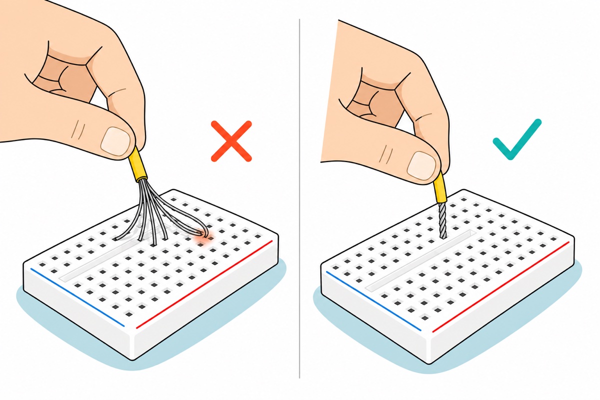
The DS18B20’s tails are fine stranded wire, tinned and splayed open at the ends, while a breadboard hole is built for a solid pin. Roll each tail tight between finger and thumb before it goes near the board — one stray strand bridging into the neighbouring row puts 5 V onto the data line. If you own an iron, a dab of solder on the twist is the sturdier fix.
| Wire | Goes to | Why |
|---|---|---|
| Probe RED | Uno 5V |
VDD — normal power, so the chip never has to steal current from the data line |
| Probe BLACK | Uno GND |
Ground reference for the bus |
| Probe YELLOW | Uno D2 |
DQ, the 1-Wire data line — any digital pin except 0 and 1 works if you change it in code, since those two carry the Serial Monitor |
| 4.7 kΩ resistor | Yellow row → 5V |
The pull-up. One for the whole bus, whatever the probe count |
OLED GND |
Uno GND |
First pin on the header — check the silkscreen before plugging in |
OLED VCC |
Uno 5V |
Display supply, sharing the probe’s rail |
OLED SCL |
Uno A5 |
I²C clock — fixed pins on an Uno, not free choice |
OLED SDA |
Uno A4 |
I²C data |
Feed the board first: one jumper from the Uno’s 5V socket to the breadboard’s red stripe, one from GND to the blue stripe. Three rows of that table want 5 V and the Uno has one socket — keep everything on the same half of the board as those two jumpers. One column of five breadboard holes is then the whole bus: the yellow tail, one leg of the 4.7 kΩ resistor and the jumper to D2 all land there, and the resistor’s other leg reaches the 5 V rail.
Only the steel capsule and its cable are sealed — the Uno, breadboard and display are not, so keep them on a dry shelf above the water line and drop the cable in over the rim. Hang the capsule in open water away from the heater’s outflow: parked against a heater it reads the heater, not the tank. Stainless also stains in saltwater — inspect the capsule when you clean a marine tank. Everything here is 5 V DC; an aquarium heater is a mains appliance, and nothing on this breadboard should be wired to switch one.
Which library does DS18B20 Arduino code need — OneWire or DallasTemperature?
The DS18B20 needs two libraries doing different jobs. OneWire by Paul Stoffregen bit-bangs the microsecond timing the bus demands; DallasTemperature by Miles Burton sits on top and turns that into readable commands. Install both from Library Manager, plus the Adafruit SSD1306 and GFX pair our DHT11 air-temperature monitor also uses.
/*
  DS18B20 waterproof probe -> 0.96" OLED water temperature monitor
  Arduino Uno + OneWire + DallasTemperature + Adafruit SSD1306

  ONE 4.7k resistor between the yellow DATA wire and 5V. The whole bus
  needs exactly one, no matter how many probes hang off the pin.
*/
#include <OneWire.h>
#include <DallasTemperature.h>
#include <Wire.h>
#include <Adafruit_GFX.h>
#include <Adafruit_SSD1306.h>

const uint8_t ONE_WIRE_PIN = 2;   // yellow probe wire lands here
const uint8_t MAX_PROBES   = 2;   // raise this if you add more probes

Adafruit_SSD1306 oled(128, 64, &Wire, -1);
OneWire oneWire(ONE_WIRE_PIN);
DallasTemperature sensors(&oneWire);

DeviceAddress probe[MAX_PROBES];
uint8_t found = 0;

void printRom(const uint8_t *addr) {
  for (uint8_t i = 0; i < 8; i++) {
    if (addr[i] < 0x10) Serial.print('0');
    Serial.print(addr[i], HEX);
  }
}

void scanBus() {
  sensors.begin();                 // runs the 1-Wire search from scratch
  uint8_t onBus = sensors.getDeviceCount();
  found = (onBus < MAX_PROBES) ? onBus : MAX_PROBES;

  Serial.print(F("Probes on the bus: "));
  Serial.println(onBus);

  for (uint8_t i = 0; i < found; i++) {
    if (sensors.getAddress(probe[i], i)) {
      Serial.print(F("  index "));
      Serial.print(i);
      Serial.print(F("  ROM "));
      printRom(probe[i]);          // note this down, label that cable
      Serial.println();
      sensors.setResolution(probe[i], 12);   // 0.0625 C steps, 750 ms conversion
    }
  }
}

void setup() {
  Serial.begin(9600);

  // Most 0.96" modules answer on 0x3C; a few are strapped to 0x3D.
  if (!oled.begin(SSD1306_SWITCHCAPVCC, 0x3C)) {
    Serial.println(F("OLED not answering - check SDA/SCL and 5V"));
    for (;;) { }
  }
  oled.setTextColor(SSD1306_WHITE);

  scanBus();

  // "YES" here means a probe has VDD tied to GND and is stealing power
  // from the data line - the usual reason readings stick at 85.00.
  Serial.print(F("Parasite power: "));
  Serial.println(sensors.isParasitePowerMode() ? F("YES") : F("no"));
}

void loop() {
  if (found == 0) {                // a missing pull-up looks like THIS, not like -127
    oled.clearDisplay();
    oled.setTextSize(1);
    oled.setCursor(0, 0);
    oled.print(F("NO PROBE FOUND"));
    oled.setCursor(0, 16);
    oled.print(F("CHECK 4.7k -> 5V"));
    oled.setCursor(0, 28);
    oled.print(F("AND YELLOW ON D2"));
    oled.display();
    scanBus();                     // keeps looking, so fixing a wire recovers it
    delay(1000);
    return;
  }

  sensors.requestTemperatures();   // blocks until the probe says it is done (750 ms max)

  oled.clearDisplay();
  oled.setTextSize(1);
  oled.setCursor(0, 0);
  oled.print(F("WATER TEMP"));

  for (uint8_t i = 0; i < found; i++) {
    float c = sensors.getTempC(probe[i]);

    oled.setTextSize(2);
    oled.setCursor(0, 18 + i * 24);

    if (c <= DEVICE_DISCONNECTED_C) {        // -127: nobody answered
      oled.print(F("--.- C"));
      Serial.println(F("-127 : no reply - check the 4.7k and the wiring"));
    } else {
      oled.print(c, 1);
      oled.print(F(" C"));
      Serial.print(i);
      Serial.print(F(" : "));
      Serial.println(c, 2);
      if (c > 84.9 && c < 85.1) {             // power-on scratchpad default
        Serial.println(F("   85.00 : read before conversion, or starved supply"));
      }
    }
  }

  oled.display();
  delay(1000);
}
On an Uno it compiles to 19,620 bytes of flash — 60% of the 32 KB — with 595 bytes of static RAM; the display library then allocates a 1,024-byte frame buffer when begin() runs, so about 1.6 KB of the Uno’s 2 KB is committed before your own variables. That is why every fixed string here is wrapped in F(): unwrapped, each would be copied into what is left instead of staying in flash. requestTemperatures() blocks until the probe reports its conversion finished — the DallasTemperature library polls the bus rather than sleeping a fixed interval, so the wait is capped by the datasheet’s 750 ms maximum at 12 bits rather than fixed at it; 9 bits drops that ceiling to 93.75 ms and coarsens the steps to 0.5 °C.
That reading has a second job if you already run our TDS water quality meter. Conductivity climbs about 2% per degree Celsius, so that build assumes 25 °C and a cooler tank reads slightly low. A DS18B20 on its own pin hands that sketch a real number instead — same Uno, one more probe, and the assumption becomes a measurement.
How do several DS18B20 probes share one Arduino pin?
Every DS18B20 leaves the factory with a 64-bit ROM code lasered into it: an 8-bit family code (28h for this part), a 48-bit serial number unique to that die, and an 8-bit CRC over the other seven bytes. No two probes answer to the same number, so the master can address one at a time on a shared wire. It finds them by walking the bus bit by bit — where two probes disagree, it takes one branch, finishes that address, then returns for the other — which is what getAddress() reads out in the sketch above.
In practice: both yellow tails into the same breadboard column, both reds to the red rail, both blacks to the blue rail, and the single 4.7 kΩ resistor stays where it is — a second one only halves the pull-up resistance for no benefit. Run the sketch with Serial Monitor open at 9600 baud and each ROM code prints once at startup. To learn which is which, cup one probe in warm water, watch which index moves, and wrap a tape flag round that cable.
Several probes landing on one rail is easier watched than described:
What do −127 and 85.00 mean on a DS18B20?
The DS18B20 has two readings that are messages rather than temperatures — and one message that never becomes a reading at all.
| Reading | What it actually is | Where to look |
|---|---|---|
Probes on the bus: 0 |
The search finished and nothing answered — no device ever pulled the line low to announce itself | The pull-up first: with no resistor the line cannot idle high, so the reset pulse gets no reply. Then the yellow tail’s column, and the pin number the sketch declares |
−127.00 |
DEVICE_DISCONNECTED_C — the master sent a reset pulse and no device answered |
A probe that answered at startup and has since stopped: a tail worked loose, a strand making intermittent contact, or a cable pinched under the tank lid |
85.00 |
The power-on default of the temperature register, still untouched | A reading taken before the conversion finished, or a supply that sags during it |
| Plausible but frozen | A real value that never updates | requestTemperatures() outside the loop, so the same scratchpad is read forever |
That +85 °C is the power-on reset value of the temperature register itself, so a chip powered but not yet finished converting hands it to any read. It also points at a starved supply, which brings in parasite power: a DS18B20 can run with VDD tied to ground, drawing what it needs from the data line while the line idles high. Our probe has three wires, so give VDD the red one and 5 V: normal power, the mode used here. Parasite mode instead needs the master to clamp the line hard high for the whole conversion, because a 4.7 kΩ resistor cannot supply the ~1.5 mA the chip draws while converting. The sketch prints Parasite power: YES if it sees that state, which means the red wire is not doing its job.
Common mistakes we see from real customers
Buying the probe and forgetting the resistor. A customer messaged us: “For the resistor: do you have a 4.7k or 10k 1/4W resistor available? I need about 10 pcs for my DS18B20 pull-up.” He had the value right and the count generous: one bus needs one resistor. The probe ships as probe only — no breakout board, no resistor.
Assuming a starter pack covers it. Another asked whether a set included “220 Ohm, 1K Ohm, 4.7K Ohm and 10K Ohm”. Read what you already own by the bands above rather than by hope, and if you are buying rather than digging, buy the value itself — one 4.7 kΩ 1/4 W part settles the whole bus.
Expecting the display to light on its own. A blank OLED beside a working probe is almost always the I²C address: most 0.96-inch modules answer on 0x3C, a few on 0x3D, and File → Examples → Wire → i2c_scanner prints whichever address is really on A4/A5, so you change that one number in oled.begin() knowing the answer rather than guessing — the same habit our LCD1602 I²C guide teaches.
FAQ
Do I really need a resistor for the DS18B20?
Yes — one 4.7 kΩ 1/4 W resistor between the data wire and 5 V, for the whole bus. Probe and Arduino can only pull the line low, so the resistor is the only component able to raise it; without it the bus never idles high and the scan finds no probe at all.
Why does my DS18B20 read −127?
−127 is the library’s DEVICE_DISCONNECTED_C sentinel: the reset pulse got no answer. If the probe was never found, the sketch reports zero devices at startup and the fault is the missing pull-up, the resistor in the wrong column, or the wrong pin. A true −127 means it answered once and stopped — a tail worked loose or a strand barely touching.
Can I use a 10 kΩ resistor instead of 4.7 kΩ?
For a single probe on the standard one-metre cable, yes: the line still reaches a valid high in roughly two microseconds against a 15 µs deadline. That margin shrinks as probes and cable add capacitance, so 4.7 kΩ is the value to keep. Two 10 kΩ in parallel give 5 kΩ.
How many DS18B20 sensors can I connect to one Arduino pin?
Enough for any tank setup. Each carries a unique 64-bit ROM address, so they share one pin and one pull-up. The limit is electrical, not a number in the library: total cable capacitance eventually blunts the rising edge.
Is the DS18B20 accurate enough for an aquarium?
Comfortably. It is specified to ±0.5 °C from −10 °C to +85 °C and resolves 0.0625 °C steps at 12 bits, so a failing heater shows up long before livestock notice.
Last updated August 2026. Stuck? Chat with us on WhatsApp.

Pingback: IoT Project Ideas for FYP: 10 You Can Finish Alone