

Tutorials
Arduino LDR Night Light: Voltage Divider, Thresholds, No Flicker
Aug
An automatic light that switches on at dusk is built from one LDR and one fixed resistor forming a voltage divider on the Arduino’s A0 pin: analogRead reads the midpoint of that divider, and two thresholds in the code — one for on, one for off — are what stop the lamp flickering at the exact moment of dusk. An LDR produces no voltage; it only changes resistance, and it is the fixed resistor that translates that into a voltage you can read.
What do you need for an LDR automatic night light?
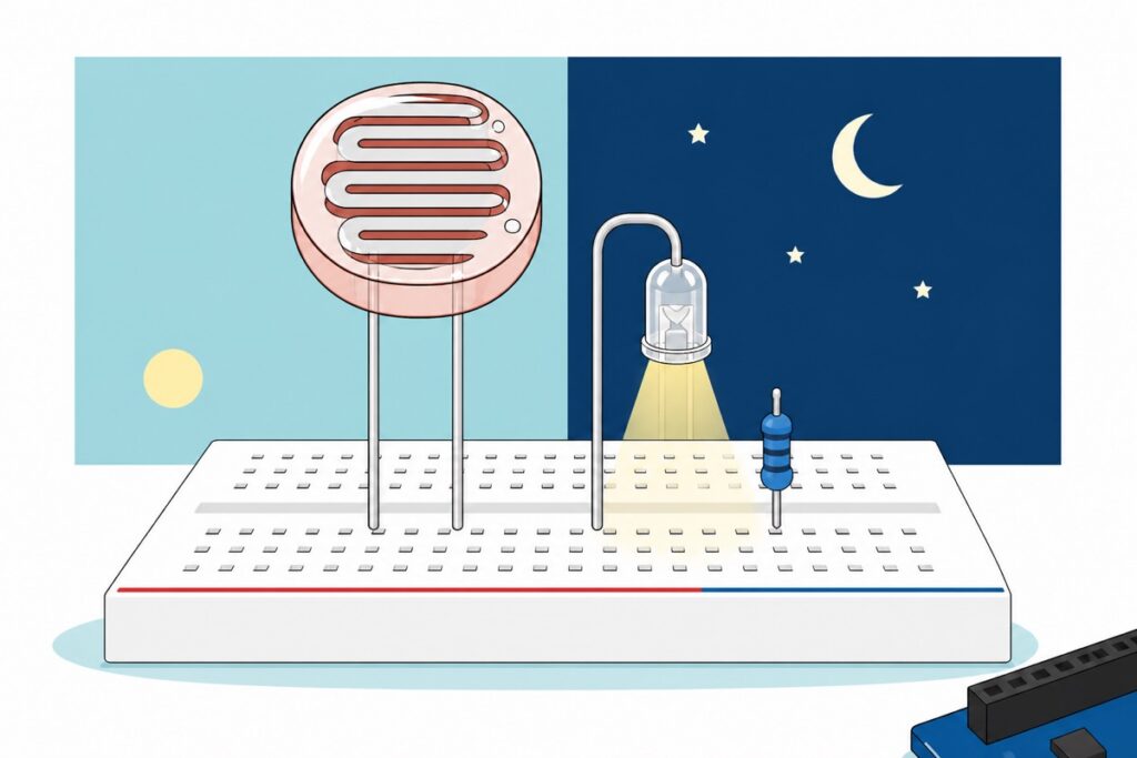
The heart of this build is the LDR (light dependent resistor) — a pale pink disc with a silver zig-zag electrode pattern across its face, two straight wire legs, no PCB and no polarity. Disc size varies between batches, and that changes nothing here, because you are not copying anyone else’s resistance figures — you measure your own unit on the Serial Monitor and set the thresholds from that number. The rest of the list gives it a brain, a lamp, and one resistor that makes its readings mean something.
Parts list — LDR automatic night light with an Arduino Uno
 Light Dependent Resistor Photo Sensor LDR Sunlight Detection Light Sensitive Resistor
 Arduino Uno Compatible SMD UNO R3 with Type B Cable - ATMEGA328P with CH340G-Microcontroller Project
 MB102 Breadboard 170 400 830 Holes Breadboard Donut Board Arduino Prototype Multi Color - BREADBOARD (400 HOLES)
 40pcs Dupont Wire 10cm 20cm 30cm for Breadboard DIY Experiment Jumper Wire Breadboard wire - DUPONT WIRE M-M 20CM
 Round Head LED 3mm / 5mm / 8mm - Red/Yellow/Blue/Green/White - 5mm LED (WHITE)
 400 pcs 1/4W Resistor Pack Resistor Kit 20 Common Value with 20 each
Optional — the module shortcut, a relay upgrade, cable and resistor kit
 Light Sensor Module Photosensitive Light Detection LDR For Arduino IOT Application
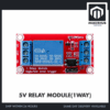 Relay Module 3.3V 5V 12V 1/2/4/8 Ways Optocoupler Trigger Relay Module 1 2 4 8 Channel Relay Module - 5V RELAY MODULE(1WAY)
 Data Cable Type-A Type-C MicroUSB Type-B 0.5m 1m 30cm 0.3m 100cm Data Transfer Upload Code - TYPE-A TO TYPE-B (1.0M)
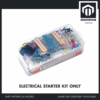 Electronic Component Set Beginner Electrical Learning Kit For Arduino Beginner Learning - ELECTRICAL STARTER KIT
The light sensor module is the ready-made shortcut: its threshold is set with the trimmer on the board, not in code. The 5V relay module upgrades the mini LED to a real 12V DC lamp. The USB A-to-B cable is the shape the Uno's square socket takes — add one if your drawer does not have that shape yet. The electronics starter kit carries strips of resistors — the strips marked 220 and 100K are visible in the photo, exactly the two values this build needs — along with LEDs, jumpers and an 830-point breadboard, a useful fallback when you have run out of loose resistors.
Two resistor values are needed: 100 kΩ for the voltage divider, and 220 Ω to limit the LED current. (10 kΩ works too; the next section shows why 100 kΩ gives a far roomier dusk reading.) Both are common values in the 1/4 W resistor pack, in your parts drawer, or on the labelled strips in the electronics starter kit. A clear-domed 5 mm white LED is our “street lamp”; for a small status indicator beside it, a 3 mm red LED is enough.
One thing should be clear from the start: this circuit responds to light level, not to people. Want a light that comes on when someone walks past? That is a motion sensor’s job — read our HC-SR501 motion sensor guide. The two are often combined: the PIR decides “someone is there”, the LDR decides “it is dark now”.
Why must an LDR use a voltage divider?
An LDR is a slab of photoconductive material: photons landing on its face free charge carriers, so more light means more paths for current, and the resistance falls. Under bright room light an LDR of this type sits at just a few kΩ; in darkness it climbs into the hundreds of kΩ, approaching 1 MΩ. That is a huge range — but it is a range of resistance.
The problem is that an Arduino’s analog pin cannot measure resistance. analogRead is a voltmeter: it weighs the voltage on the pin against the 5 V reference and returns a number from 0 to 1023, one step per ~4.9 mV. There is no current source inside the chip that can “interrogate” a resistance. So if the LDR runs from 5 V straight to A0 and nothing else, almost no current flows through it — pin leakage on the ATmega328P is 1 µA maximum, per its datasheet — so almost no voltage drops across the LDR, A0 simply sits near 5 V, and the reading is stuck near 1023 whether it is noon or midnight. Connect it to GND alone instead and you get the mirror image: that same leakage current is far too small to lift any voltage across the LDR, so the pin is pulled hard to 0 V and the reading sticks at the bottom of the scale. Either way, the LDR’s resistance never becomes a number.
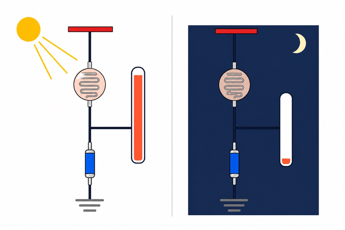
A voltage divider solves it with one fixed resistor. Run the LDR from 5 V to a point, and a fixed resistor — take 10 kΩ as a first example — from that same point to GND: now a small current flows through both, and the voltage at the midpoint is 5 V × 10 kΩ ÷ (RLDR + 10 kΩ). The LDR’s rising and falling resistance now pushes that voltage up and down, and that is what the ADC reads. There is a free bonus here: the same 5 V rail supplies the divider and serves as the ADC’s reference, so if that rail sags a little — a laptop USB port versus a wall charger — both sides of the ratio sag together and the reading barely moves. The thresholds you calibrate stay valid even when you change supply.
| LDR resistance | Roughly | A0 voltage (10 kΩ resistor) | analogRead |
analogRead with 100 kΩ |
|---|---|---|---|---|
| 5 kΩ | bright daylight | 3.33 V | 682 | 974 |
| 20 kΩ | lit room | 1.67 V | 341 | 852 |
| 50 kΩ | early dusk | 0.83 V | 170 | 682 |
| 100 kΩ | dusk | 0.45 V | 93 | 512 |
| 300 kΩ | after sunset | 0.16 V | 33 | 256 |
| 1 MΩ | dark | 0.05 V | 10 | 93 |
The last two columns answer the “which value should I use” question. A voltage divider is most sensitive when the fixed resistor is close to the LDR’s resistance at the light level you want to distinguish. With 10 kΩ, the 50 kΩ–300 kΩ dusk band spans only 170 down to 33 — 137 steps. With 100 kΩ, that same light band spans 682 down to 256, which is 426 steps, three times as much room in which to place a threshold. The reason shows in the formula: when the fixed resistor is far smaller than the LDR, nearly the whole 5 V drops across the LDR and the midpoint is squeezed close to 0 V, so even a large change in resistance moves the reading only a few steps. Both values work, but the build in this guide uses 100 kΩ, because that roomiest span falls exactly on the light levels that make the decision.
How do you wire the LDR, the LED and an Arduino Uno?
Every part of this build sits on a 400-point breadboard, and male-to-male jumpers carry each row to the female sockets on the Uno. Feed the rails first: one jumper from the Uno’s 5V socket to the breadboard’s red strip, one from GND to the blue strip. After that, every 5 V and GND connection is taken from a rail instead of fighting over a single socket on the board.
| Connection | Goes to | Why |
|---|---|---|
Uno 5V |
breadboard red strip | Supply for the voltage divider |
Uno GND |
breadboard blue strip | Zero reference for the ADC and for the LED |
| LDR first leg | red strip | The LDR has no polarity — either leg will do |
| LDR second leg | empty column (call it column A) | Midpoint of the voltage divider |
| 100 kΩ resistor | column A → blue strip | Bottom leg of the divider; without it A0 sticks near 5 V |
| Jumper | column A → Uno A0 |
The ADC reads the midpoint voltage |
Uno D9 |
one leg of the 220 Ω resistor | The output pin that switches the lamp on |
| 220 Ω resistor, second leg | LED long leg (anode) | Limits the LED current |
| LED short leg (cathode) | blue strip | Completes the LED circuit to GND |
The order of those two components matters even though the LDR itself has no polarity: LDR on the 5 V side and fixed resistor on the GND side means the reading rises as it gets brighter. Swap the two and the divider still works, only the reading is inverted — a big number now means dark — and the two thresholds in the sketch below will act backwards. If your lamp comes on during the day and goes off at night, check this order before touching any of the numbers.
That 220 Ω resistor is not decoration. A white LED drops about 3.1 V, so 220 Ω carries the leftover 1.9 V and sets the current at roughly 9 mA — comfortably under the ATmega328P’s 20 mA per-pin limit. Connect an LED straight to a pin with no resistor and the only thing limiting the current is the pin’s own internal resistance, which damages the LED, the pin, or both.
One assembly decision is easy to overlook: point the LDR away from the LED. If the LDR can see its own lamp, the lamp switching on raises the light reading, and you have just built a feedback loop that switches that lamp straight back off.
One more thing before it becomes a real lamp: this circuit has to run all night, not only while your laptop is open. The Uno takes power from any USB phone charger through the same cable, or from a 7–12 V DC supply through the black barrel jack on the edge of the board. Because the lamp state is decided purely by the current light reading, there is nothing to set up again whenever power goes out and comes back.
The physical layout of the LDR and the resistor on the breadboard, if you want to see it first:
How do you calibrate the thresholds, and why two numbers?
The threshold numbers depend on the resistor you chose, on your particular LDR, and on the light where the lamp will be installed. Upload the sketch below, open the Serial Monitor at 9600 baud, put the circuit where it will actually live, and watch the numbers at the moment you want the lamp to switch. Those are your thresholds.
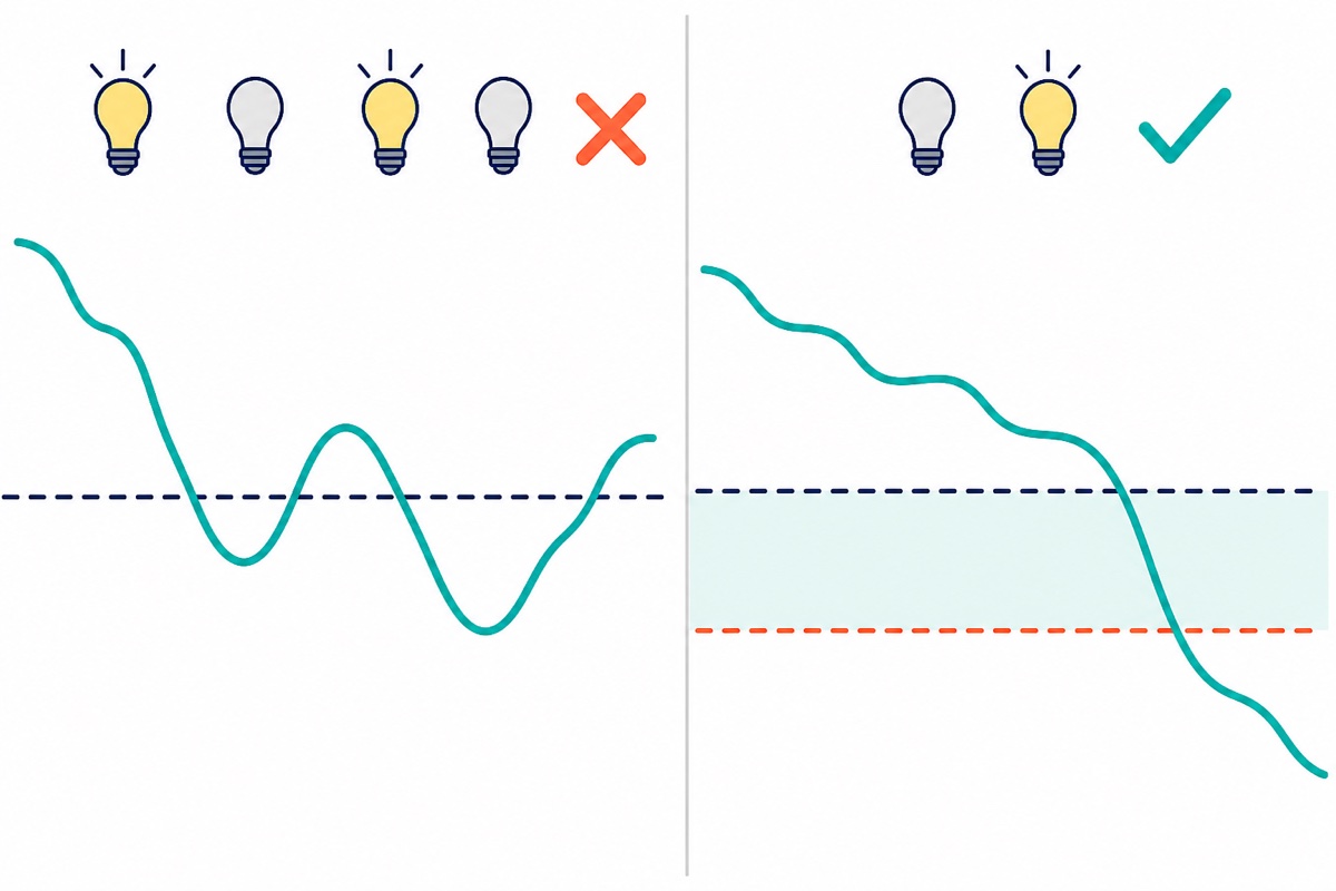
Now the part that separates a tidy dusk light from an annoying one. If you use only one threshold, slowly falling dusk light will sit near that number for tens of minutes. A ripple of a few steps from ADC noise, a passing cloud, or a neighbour’s light is enough to cross it again and again, and your lamp flickers.
Two thresholds solve it. The lamp switches on when the reading falls below AMBANG_ON, but only switches off when the reading rises above the higher AMBANG_OFF. Between those two numbers nothing changes — the current state is held. That is hysteresis, and the gap must be wider than two things: your normal reading ripple, and the jump in the reading caused by the lamp itself. Measure the second one once: note the reading with the LED forced on and forced off under the same ambient light, and the gap between the two thresholds must exceed that difference.
This sketch adds one more layer: a change in light must hold for three seconds before the lamp acts. Hysteresis handles the ripple around the threshold; the timer handles short events such as car headlights sweeping past or a hand passing over.
/*
  LDR automatic night light — Arduino Uno
  LDR + 100k fixed resistor = voltage divider on A0.
  BIG reading = bright, SMALL reading = dark
  (LDR on the 5V side, fixed resistor on the GND side).

  Two thresholds (hysteresis) + a hold time so the lamp
  does not flicker at dusk.
*/

const uint8_t PIN_LDR   = A0;   // midpoint of the voltage divider
const uint8_t PIN_LAMPU = 9;    // LED (through 220R) or the relay IN pin

// Change these two numbers after calibrating on the Serial Monitor.
const int AMBANG_ON  = 400;     // below this = dark enough  -> on
const int AMBANG_OFF = 550;     // above this = bright enough -> off

const unsigned long TEMPOH_SAH = 3000UL;  // light must hold for 3 seconds
const uint8_t SAMPEL = 16;                // average, drop the ADC noise

bool lampuNyala = false;
bool sedangTunggu = false;
unsigned long mulaBerubah = 0;

int bacaPurata() {
  long jumlah = 0;
  for (uint8_t i = 0; i < SAMPEL; i++) {
    jumlah += analogRead(PIN_LDR);
    delay(2);
  }
  return (int)(jumlah / SAMPEL);
}

void setup() {
  pinMode(PIN_LAMPU, OUTPUT);
  digitalWrite(PIN_LAMPU, LOW);
  Serial.begin(9600);
  Serial.println(F("Kalibrasi: tutup LDR dgn jari = gelap, sinar lampu = terang"));
}

void loop() {
  int cahaya = bacaPurata();

  // Hysteresis: each state has its own threshold, so between
  // AMBANG_ON and AMBANG_OFF nothing changes at all.
  bool mahuNyala = lampuNyala;
  if (!lampuNyala && cahaya < AMBANG_ON)  mahuNyala = true;
  if (lampuNyala  && cahaya > AMBANG_OFF) mahuNyala = false;

  // Hold time: headlights or the shadow of a hand do not last long enough.
  if (mahuNyala != lampuNyala) {
    if (!sedangTunggu) {
      sedangTunggu = true;
      mulaBerubah = millis();
    } else if (millis() - mulaBerubah >= TEMPOH_SAH) {
      lampuNyala = mahuNyala;
      digitalWrite(PIN_LAMPU, lampuNyala ? HIGH : LOW);
      sedangTunggu = false;
    }
  } else {
    sedangTunggu = false;          // the light went back, cancel the count
  }

  Serial.print(F("cahaya="));
  Serial.print(cahaya);
  Serial.print(F("  lampu="));
  Serial.println(lampuNyala ? F("ON") : F("OFF"));
  delay(200);
}
On the Uno this sketch uses 2,718 bytes of flash (8% of 32 KB) and 194 bytes of static RAM, so there is plenty of room to add a display or a clock later. bacaPurata() takes 16 readings and averages them: a single ADC reading can wobble a few steps, and the average removes that small ripple before it gets anywhere near your thresholds.
This is where our light sensor module deserves an honest look. It is a three-pin HW-072 board — VCC, GND and DO — with a blue trimmer and an LM393 comparator on it: the trimmer sets one cut-off point in hardware, and DO gives a yes-or-no answer only. There is no AO pin, so analogRead and two thresholds in code are not an option there. As a ready-made light switch it is neat and quick (the 90° right-angle male header on it needs female-to-male jumpers) — but to control the gap between on and off yourself, the bare LDR wins.
How do you upgrade to a 12 V lamp with a relay?
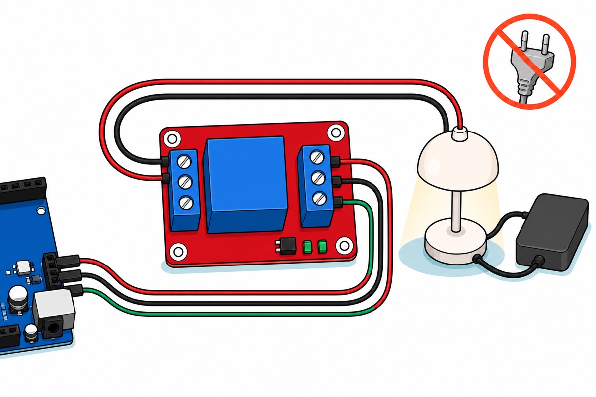
A 5V relay module turns the mini LED into a real DC lamp. The red board carries a blue Songle relay and two blue screw terminal blocks: the control side is marked IN, DC- and DC+, the load side NO, COM and NC. Both are screw terminals, so the pin ends of male-to-male jumpers clamp straight under the screws — no soldering.
DC+ to the 5 V rail, DC- to the GND rail, and IN to D9. Remove the LED and the 220 Ω resistor first, and take IN straight to D9 with no resistor — IN is a signal input that already carries its own series resistor on the board, not a load whose current needs limiting. In one corner of the board sits a jumper block marked L and H that selects whether the IN pin is triggered by a low or a high signal. The sketch above sends HIGH to switch the lamp on, so that jumper needs to sit on the H pair of pins. In our product photo it is already there, so usually there is nothing to move — glance at it before wiring to confirm, because if it has strayed to L your lamp will come on during the day and go off at night. Our guide to using a relay module safely covers the load side in more detail.
Safety, and this is not optional advice. The relay’s contacts carry two ratings printed on the case, 10A 250VAC and 10A 30VDC, and it is the second number that is relevant here — it is far above what any 12 V garden lamp draws. This build stays low-voltage DC only — a 12 V lamp at most, with its own supply. Never wire 240 V mains into this breadboard circuit. Mains wire on a breadboard cannot be insulated, there is no touch isolation, and one wire pulling loose is enough to kill. Mains work is the job of a licensed electrician, not an Arduino project.
A relay only switches — it does not supply power. Your 12 V supply goes into COM, NO goes to the lamp’s positive terminal, and the lamp’s negative returns to the supply’s negative. Notice what is not in that sentence: no wire from the 12 V supply to the Uno’s GND. The relay’s contacts are a magnetically pulled piece of metal, isolated from its coil, so the 12 V circuit and the 5 V circuit need not share a ground at all. That is what makes it different from a transistor switch, which does demand a common ground. If your system already runs on 12 V — a solar panel or a car, say — the 12V coil version suits better because it is powered straight from that 12 V rail; it cannot be run from the Uno’s 5 V pin.
Common mistakes we see
The LDR wired straight to A0. This is the most frequent pattern: LDR from 5 V to A0, and nothing else. With no fixed resistor to GND almost no current flows through the LDR, so almost no voltage drops across it: the pin sits near 5 V and the reading is stuck near 1023 without tracking the light at all. That fixed resistor is not an extra — it is half of the sensor.
Copying threshold numbers off the internet. Someone else’s thresholds came out of their resistor, their LDR unit and their room; the 400 and 550 in the sketch above are a starting point for a 100 kΩ divider so the code will run, not an answer.
Blaming the LDR when the lamp flickers. Flickering at dusk almost always means one threshold, too narrow a hysteresis gap, or an LDR that can see its own lamp — widen the gap first, then turn the LDR to face somewhere else. If the readings look odd even in complete darkness, measure the LDR’s resistance directly with a multimeter before blaming the code; our guide to using a digital multimeter shows how.
FAQ
Why can’t an LDR be connected straight to pin A0?
Because analogRead measures voltage, not resistance. With no fixed resistor to GND almost no current flows through the LDR, so almost no voltage drops across it: A0 simply sits near 5 V and the reading is stuck near 1023 whether it is bright or dark. The fixed resistor is what turns resistance into voltage.
Which resistor value for an LDR voltage divider — 10 kΩ or 100 kΩ?
Both work. A divider is most sensitive when the fixed resistor is close to the LDR’s resistance at the light level you want to distinguish; at dusk that is tens to hundreds of kΩ, so 100 kΩ gives a roomier range of readings.
Why does my automatic light flicker at dusk?
Because your code uses one threshold, and dusk light sits near that number for a long time. Use two thresholds, and make sure the gap between them is bigger than the jump in the reading caused by the lamp itself.
Can I use the light sensor module and do analogRead?
Our three-pin HW-072 module brings out VCC, GND and DO only, so you read it with digitalRead and set its threshold with the trimmer. For two thresholds in code, use a bare LDR with a voltage divider.
Can this circuit switch a 240 V lamp?
No. This circuit is designed for low-voltage DC — an LED, or a 12 V lamp through a relay module with its own supply. Mains wiring needs proper isolation, protection and an enclosure, and in Malaysia it is a licensed electrician’s work.
Last updated August 2026. Stuck? Chat with us on WhatsApp.
