

Tutorials
TCS230 Colour Sensor with Arduino: Detect and Sort by Colour
Aug
The TCS230 never reports a colour. It reports one number at a time — a frequency, through whichever filter you selected with two pins — so a colour reading is three measurements in a row, and your sketch, not the chip, decides what they add up to. Set S0 HIGH, S1 LOW, time each channel with pulseIn(), and calibrate against a white card first.
What does a TCS230 colour sensor actually measure?
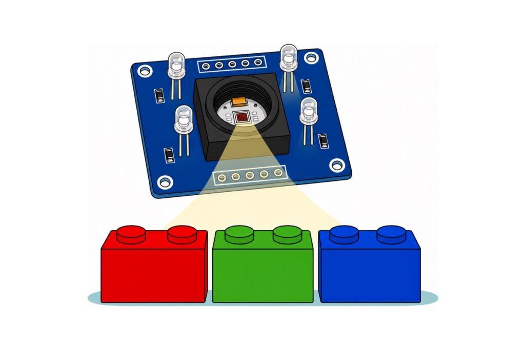
The TCS230 carries a single 8×8 array of photodiodes, and the 64 are not identical: sixteen sit behind a red filter, sixteen behind green, sixteen behind blue and sixteen behind no filter at all. Only one group is connected to the converter at any moment, and S2 and S3 choose which. So there is no “read the colour” call — only select red, measure; select green, measure; select blue, measure.
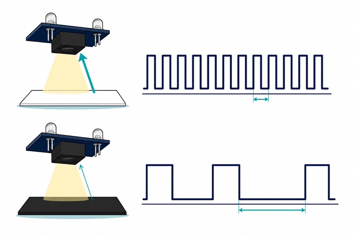
What arrives at OUT is not a voltage either. The converter turns the selected group’s photocurrent into a 50%-duty square wave whose frequency is proportional to how much light landed on it, over a 2.7–5.5 V supply, per the TAOS TCS230 datasheet. Bright means fast, dark means slow.
| S2 | S3 | Photodiode group connected |
|---|---|---|
| LOW | LOW | Red |
| LOW | HIGH | Blue |
| HIGH | LOW | Clear — no filter |
| HIGH | HIGH | Green |
S0 and S1 then divide that frequency down before it leaves the chip, and the setting decides whether an Arduino can time the wave at all.
| S0 | S1 | Output scaling | Full-scale frequency | Half-period at full scale |
|---|---|---|---|---|
| LOW | LOW | power down | — | — |
| LOW | HIGH | 2% | 10–12 kHz | 42–50 µs |
| HIGH | LOW | 20% | 100–120 kHz | 4–5 µs |
| HIGH | HIGH | 100% | 500–600 kHz | 0.8–1 µs |
Arduino’s pulseIn() reference documents it as working on pulses from 10 µs upward, and that number picks the row. At 100% a bright reading is a fraction of 10 µs, so light objects collapse into the same meaningless value. At 2% nothing is too fast, but a dark object stretches one measurement into milliseconds, and three of those per reading is visible lag. 20% puts ordinary indoor readings in the tens of microseconds; the 4–5 µs in that row is full scale, a brightness the module’s own four LEDs never reach off an everyday object.
Parts list — the sensor, a screen to watch it on, and the headers and jumpers that reach it
 TCS230 Color Sensor Module Light to Frequency Converter RGB Detection for Arduino DIY Projects Robotics
 0.96‘ OLED Display Module Blue White Screen I2C IIC Serial 128X64 LCD Display Board - 0.96' OLED WHITE
 Arduino Uno Compatible SMD UNO R3 with Type B Cable - ATMEGA328P with CH340G-Microcontroller Project
 Sensor Shield V5.0 Arduino Uno R3 Shield For Arduino Protoype Application
 40pcs Dupont Wire 10cm 20cm 30cm for Breadboard DIY Experiment Jumper Wire Breadboard wire - DUPONT WIRE F-F 20CM
 2.54mm Pin Header Female Male Single Row Header 40P Connector Black White Red Yellow Green Blue - 40P MALE HEADER (BLACK)
Parts list
| Item | Price | Qty | |
|---|---|---|---|
 Soldering Service for Circuit Boards & Electronics - 10 Pins Soldering ServiceSOLSE10 Soldering Service for Circuit Boards & Electronics - 10 Pins Soldering ServiceSOLSE10 | RM1.40 |
The TCS230 module needs exactly 10 header pins soldered. If you would rather not solder, add the 10-pin soldering service and we fit the strip for you.
How do you wire a TCS230 to an Arduino Uno?
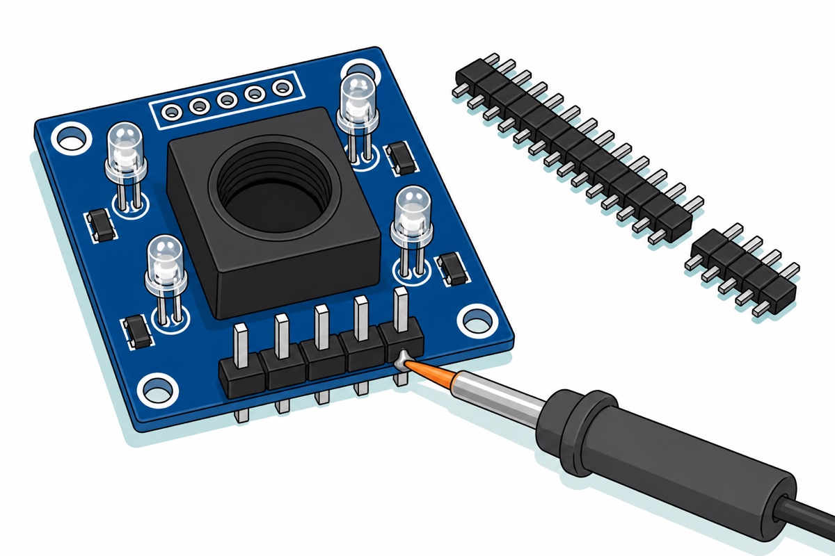
The TCS230 module presents its two 5-pin rows as bare plated through-holes, so the first job is soldering. Snap two 5-way pieces off the 40-pin 2.54 mm male strip in the parts list and push them in from the lens side, so the pins emerge at the back and no jumper shell sits in the light path; our header-soldering guide walks the technique, or the 10-pin soldering service covers it if you have no iron.
The two rows carry different pins and run opposite ways round, so read the silkscreen rather than the position: one edge runs GND OUT S2 S3 VCC, the other runs VCC S1 S0 LED GND, each with a square pad at pin 1. Those rows sit on opposite edges of a 33.2 mm square board, about 30 mm apart — wider than the 28 mm span across a mini breadboard’s two banks, so the module cannot straddle one. Use a Sensor Shield V5.0 on the Uno instead: it republishes every digital pin as a three-pin male block labelled G, V and S, plus a four-pin IIC port for the OLED. With male pins at both ends, all twelve links are female-to-female jumpers, and 20 cm leads let the sensor dangle where you point it.
The pin marked LED is not a logic pin. It switches the module’s four onboard white LEDs, which the board’s manual puts at roughly 25 mA together, and the board confirms it: the resistor beside each LED is marked 331, meaning 330 Ω, and a white LED drops about 3.1 V, so each branch draws (5 − 3.1) / 330 = 5.8 mA and four ≈ 23 mA. The ATmega328P datasheet allows 40 mA per I/O pin as an absolute maximum and only specifies the pin’s output voltage up to 20 mA. Tie LED to 5V and leave the lamps on — which is what colour measurement wants anyway.
The shield’s yellow SEL jumper, beside the blue screw terminal, feeds the digital blocks’ V pins from the Uno’s own 5V. Leave it where it came — pull it and every V pin on the D0–D13 blocks goes dead, which reads convincingly as a faulty sensor rather than a missing jumper. Connect nothing to the screw terminal: an outside supply with SEL fitted lands straight on the Uno’s 5V rail.
| Module pin (silkscreen) | Where it goes on the shield | Uno pin behind it |
|---|---|---|
| TCS230 OUT | D8 block, S | D8 |
| TCS230 S0 | D4 block, S | D4 |
| TCS230 S1 | D5 block, S | D5 |
| TCS230 S2 | D6 block, S | D6 |
| TCS230 S3 | D7 block, S | D7 |
| TCS230 VCC | any block’s V | 5V |
| TCS230 GND | any block’s G | GND |
| TCS230 LED | any spare block’s V | 5V — never a digital pin |
| OLED GND | IIC header, − | GND |
| OLED VCC | IIC header, + | 5V |
| OLED SCL | IIC header, SCL | A5 |
| OLED SDA | IIC header, SDA | A4 |
The OLED’s header runs GND, VCC, SCL, SDA — ground first, the reverse of the usual VCC-first order — while the shield’s IIC port runs SCL, SDA, −, +. Land those four one at a time, not as a straight-across ribbon. Its header ships pre-soldered; the same panel drives our rotary encoder OLED menu.
Why does a red object give the LOWEST red reading?
Because the TCS230’s OUT pin is timed, not read. pulseIn(OUT, LOW) does not measure light — it measures the length of the LOW half of that square wave in microseconds, which is half a period. Period is 1 / frequency, so the number you get back is 500000 / f: 25 at 20 kHz, 100 at 5 kHz.
Put a red brick under the red filter and it reflects red strongly, so the frequency climbs, the half-period shrinks, and the number gets smaller. Your best-matching channel is the one with the lowest raw count: raw counts from a TCS230 measure darkness.
How do you calibrate a TCS230, and why is calibration the whole project?
The TCS230’s raw counts drift with distance, room lighting and how bright the object is to begin with, so you pin two ends down. Fix the height first and never change it — around 10–30 mm from the lens suits most objects, close enough that the four LEDs’ cones overlap on the target. At that height, hold a white card and note the three raw numbers — the smallest you will see. Then hold something matt black and note those — the largest.
map(raw, white, black, 255, 0) then converts a raw count into 0–255. Note the output range runs backwards: white is the small raw value and has to land on 255. That single reversed argument is where the inversion gets undone.
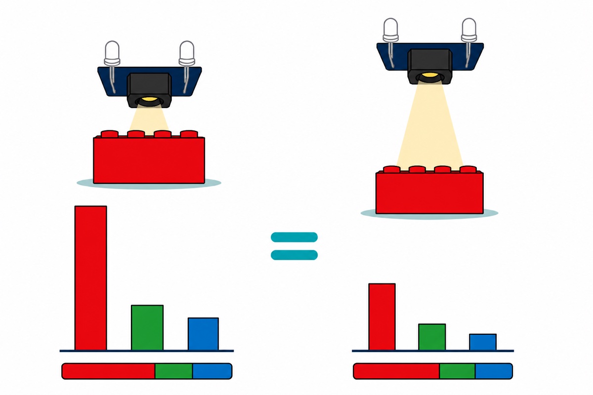
That is still not enough, and this is the step most guides skip. Move the object 5 mm further away and all three normalised values shrink together, because less light comes back overall. So divide each by their total: r = R / (R+G+B). Brightness cancels and only proportion survives. A red brick whose three 0–255 values read 210/70/60 up close gives ratios of 617/205/176 per thousand; back it off until they read 120/40/34 and the ratios are 618/206/175 — the same verdict from very different numbers, and the reason a sorter stays repeatable. The integer division truncates, so the three never quite total 1000.
The four white LEDs ringing the lens exist for the same reason: the sensor measures reflected light, so a varying light source means varying readings. Keep them on and shroud the gap from room light. Watching the numbers move as objects go under the sensor is worth a few minutes here:
What does the Arduino sketch for a TCS230 look like?
The TCS230 sketch is three reads, a normalise, a ratio, then nearest-match against your own references. Install Adafruit SSD1306 and Adafruit GFX Library from the Library Manager first. Every number in the two calibration blocks is a placeholder — run it, read the raw line in Serial Monitor at 9600, paste in yours.
// TCS230 colour sensor + 0.96" SSD1306 OLED on an Arduino Uno.
// Wiring: OUT -> D8, S0 -> D4, S1 -> D5, S2 -> D6, S3 -> D7,
//         VCC -> 5V, GND -> GND, LED -> 5V (never a digital pin: ~25 mA).
//         OLED SCL -> A5, SDA -> A4, VCC -> 5V, GND -> GND.

#include <Wire.h>
#include <Adafruit_GFX.h>
#include <Adafruit_SSD1306.h>

#define SCREEN_WIDTH 128
#define SCREEN_HEIGHT 64
#define OLED_RESET -1
#define OLED_ADDR 0x3C   // silkscreen says 0x78; that is the 8-bit form, 0x78 >> 1 = 0x3C

Adafruit_SSD1306 display(SCREEN_WIDTH, SCREEN_HEIGHT, &Wire, OLED_RESET);

const uint8_t PIN_S0  = 4;
const uint8_t PIN_S1  = 5;
const uint8_t PIN_S2  = 6;
const uint8_t PIN_S3  = 7;
const uint8_t PIN_OUT = 8;

// ---- STEP 1: your own calibration, in raw microseconds (R, G, B) ----------
// Hold a WHITE card at your working distance, read the "raw" line on Serial
// Monitor, paste the three numbers here. Repeat with something matt BLACK.
const uint16_t WHITE_RAW[3] = {  26,  30,  25 };
const uint16_t BLACK_RAW[3] = { 240, 265, 230 };

// ---- STEP 2: reference ratios x1000, measured on YOUR objects -------------
// Print the ratio line while holding each object, then paste the triples here.
const int16_t REF[4][3] = {
  { 560, 235, 205 },   // red
  { 235, 520, 245 },   // green
  { 205, 270, 525 },   // blue
  { 333, 333, 334 }    // white / grey
};
const char *const NAME[4] = { "RED", "GREEN", "BLUE", "WHITE" };

// One measurement. S2/S3 pick which photodiode group is connected to the
// converter; pulseIn times the LOW half of a 50%-duty square wave, so the
// number it returns is half a period - MORE light gives a SMALLER number.
uint16_t readRaw(uint8_t s2, uint8_t s3) {
  digitalWrite(PIN_S2, s2);
  digitalWrite(PIN_S3, s3);
  delay(10);                                        // let the new filter settle
  unsigned long us = pulseIn(PIN_OUT, LOW, 50000UL);
  if (us == 0 || us > 50000UL) return 50000;        // timed out: effectively black
  return (uint16_t)us;
}

// Turn a raw half-period into 0-255 "how much of this colour came back".
// The output range is written backwards on purpose: white is the SMALL raw
// value and has to land on 255.
uint8_t normalise(uint16_t raw, uint16_t white, uint16_t black) {
  long v = map((long)raw, (long)white, (long)black, 255L, 0L);
  return (uint8_t)constrain(v, 0L, 255L);
}

void setup() {
  pinMode(PIN_S0, OUTPUT);
  pinMode(PIN_S1, OUTPUT);
  pinMode(PIN_S2, OUTPUT);
  pinMode(PIN_S3, OUTPUT);
  pinMode(PIN_OUT, INPUT);

  digitalWrite(PIN_S0, HIGH);   // S0 HIGH, S1 LOW = 20% output scaling,
  digitalWrite(PIN_S1, LOW);    // 100-120 kHz full scale - what pulseIn can time

  Serial.begin(9600);
  if (!display.begin(SSD1306_SWITCHCAPVCC, OLED_ADDR)) {
    Serial.println(F("No SSD1306 at 0x3C - check SDA/SCL and 5V"));
    for (;;) { }
  }
  display.setTextColor(SSD1306_WHITE);
}

void loop() {
  uint16_t raw[3];
  raw[0] = readRaw(LOW,  LOW);    // red filter group
  raw[1] = readRaw(HIGH, HIGH);   // green filter group
  raw[2] = readRaw(LOW,  HIGH);   // blue filter group

  uint8_t rgb[3];
  for (uint8_t i = 0; i < 3; i++) {
    rgb[i] = normalise(raw[i], WHITE_RAW[i], BLACK_RAW[i]);
  }

  // Ratios, not levels. Dividing by the total throws away "how bright" and
  // keeps only "what colour", which is what survives the object moving.
  uint16_t sum = (uint16_t)rgb[0] + rgb[1] + rgb[2];
  if (sum == 0) sum = 1;
  int16_t ratio[3];
  for (uint8_t i = 0; i < 3; i++) {
    ratio[i] = (int16_t)((1000L * rgb[i]) / sum);
  }

  // Nearest reference in ratio space: squared distance, smallest wins.
  uint8_t best = 0;
  int32_t bestDist = 2147483647L;
  for (uint8_t k = 0; k < 4; k++) {
    int32_t d = 0;
    for (uint8_t i = 0; i < 3; i++) {
      int32_t e = (int32_t)ratio[i] - REF[k][i];
      d += e * e;
    }
    if (d < bestDist) { bestDist = d; best = k; }
  }

  Serial.print(F("raw "));
  for (uint8_t i = 0; i < 3; i++) { Serial.print(raw[i]); Serial.print(' '); }
  Serial.print(F(" rgb "));
  for (uint8_t i = 0; i < 3; i++) { Serial.print(rgb[i]); Serial.print(' '); }
  Serial.print(F(" ratio "));
  for (uint8_t i = 0; i < 3; i++) { Serial.print(ratio[i]); Serial.print(' '); }
  Serial.print(F(" -> "));
  Serial.println(NAME[best]);

  display.clearDisplay();
  display.setTextSize(2);
  display.setCursor(0, 0);
  display.println(NAME[best]);
  display.setTextSize(1);
  display.setCursor(0, 24);
  display.print(F("R ")); display.print(rgb[0]);
  display.print(F("  G ")); display.print(rgb[1]);
  display.print(F("  B ")); display.println(rgb[2]);
  display.setCursor(0, 40);
  display.print(ratio[0]); display.print(F(" / "));
  display.print(ratio[1]); display.print(F(" / "));
  display.println(ratio[2]);
  display.setCursor(0, 54);
  display.print(F("fit ")); display.print(bestDist);
  display.display();

  delay(200);
}
It compiles to 16,160 bytes of flash and 587 bytes of globals — but display.begin() claims another 1024 for the frame buffer at run time, which the IDE’s figure never shows, so the true SRAM cost is about 1611 of the Uno’s 2048. The fit figure on the display is the winning reference’s squared distance: small is a confident match, large a doubtful one. One sanity check while calibrating: if the white card returns raw values under about 10, you are at pulseIn()‘s floor — lift the sensor slightly, or drop to 2% scaling. That is S0 LOW and S1 HIGH — raising S1 alone leaves S0 HIGH, which is the 100% row, and shortens the pulse further.
Common mistakes we see from real customers
Red objects give the lowest red number, so the sensor looks wired wrong. It is wired right. pulseIn() returns a half-period, so more light gives a shorter pulse. Normalise before comparing anything.
Readings jump whenever a hand passes overhead. Room light is reaching the object alongside the module’s own LEDs. The classifier is only as stable as its illumination: fix the height, shroud the gap.
Every colour classifies the same, or everything reads black. Usually one of three: the header strip was never soldered and a jumper is only resting in a hole, the shield’s SEL jumper has been pulled so the sensor’s V pin is dead, or LED was left unconnected and nothing is lighting the object.
An unfamiliar object is still named, confidently. Nearest-match has no reject case: it returns the closest of your four references whatever you hold up, so a yellow brick still lands on one of them. Note where fit sits for objects you know and reject anything worse — an UNKNOWN chute beats a wrong one.
It worked on the desk and fails on the rig. Calibration is distance-specific. Re-record white, black and every reference ratio at the height the finished machine actually uses.
FAQ
Is the TCS230 the same as the TCS3200?
For your sketch, yes. Both share a programming model and pin order — S0/S1 scaling, S2/S3 filter select, OUT frequency — so code for either runs unchanged here. This board is the one usually listed as the GY-31, silkscreened Color Sensor across the back.
Do I need to solder the TCS230 module?
Yes — its two 5-pin rows are plated through-holes that take a 2.54 mm male header. The parts list includes a 40-pin strip to snap two 5-way pieces from, or add the 10-pin soldering service and we fit it.
Why must the LED pin go to 5V instead of a digital pin?
It drives four white LEDs through 330 Ω resistors, roughly 23–25 mA in total — above the 20 mA at which the ATmega328P datasheet still specifies an output pin’s voltage, and close to its 40 mA absolute maximum. Constant illumination suits measurement better anyway.
Why does the sensor need a white card before it works?
The TCS230 measures reflected light, so raw counts depend on distance and room lighting as much as on colour. A white and a black reading at your working distance give map() the two ends of the scale.
Can it tell light blue from dark blue?
Only if you keep brightness in the picture. Ratios deliberately discard it, so a pale and a deep blue of the same hue land on the same triple. Store the pre-ratio 0–255 sum beside each reference as a second test.
A colour classifier is the eye of a sorting machine, not the whole of it. Our 28BYJ-48 stepper guide covers the arm, and the line-follower build shows the other kind of optical sensing — reflectance, light against dark.
Last updated August 2026. Stuck? Chat with us on WhatsApp.
